Dual-Corded Power and Fault Tolerance: Past, Present, and Future
Details of dual-corded power change, but the theme remains the same.
Uptime Institute has worked with owners and operators of data centers since the early 1990s. At the time, data center owners used single-corded IT devices for even their most critical IT assets. Figure 1 shows a selection of the many potential sources of outage in the single path.
Early on, Site Uptime Network (now the Uptime Institute Network) founder Ken Brill recognized that outages due to faults or maintenance in the critical distribution system were a major problem in high availability computing. The Uptime Institute considers the critical distribution to include the power supply to IT devices from the UPS output to any PDU (power distribution unit), panel, or remote power panel (RPP), and the power distribution down to the rack via whip or bus duct.
Ahead of their time, Ken Brill and the Network created the Fault Tolerant Power Compliance Specification in 2000 to address the sources of outages, and updated it in 2002. Then, in 2004 Uptime Institute produced the paper Fault Tolerant Power Certification is Essential When Buying Products for High-Availability to directly address the issue. When this paper was written, four years after the Fault Tolerant Power Compliance Specification was first issued, critical distribution failures continued to cause the majority of data center outages.
“Fault-Tolerant Power Compliance Specification Version 2.0” lists the required functionality of Fault Tolerant dual-corded IT devices as defined by the Uptime Institute.
In the mid-1990s, the Uptime Institute led the data center industry in establishing Tiers as a way to define the performance characteristics of data centers. Each Tier builds upon the previous Tier, adding maintenance opportunity and Fault Tolerance. This progress culminated in the 2009 publication of the Tier Standard: Topology, which established Tiers as progressive maintenance opportunities and fault tolerance. The Tier Standard also included the requirement for dual-corded devices in Tier III and Tier IV objective data centers. Tier III data centers have dual power paths to provide Concurrent Maintainability of each and every component and path. Tier IV data centers require the same dual power paths for Concurrent Maintainability and add the ability to autonomously respond to failures.
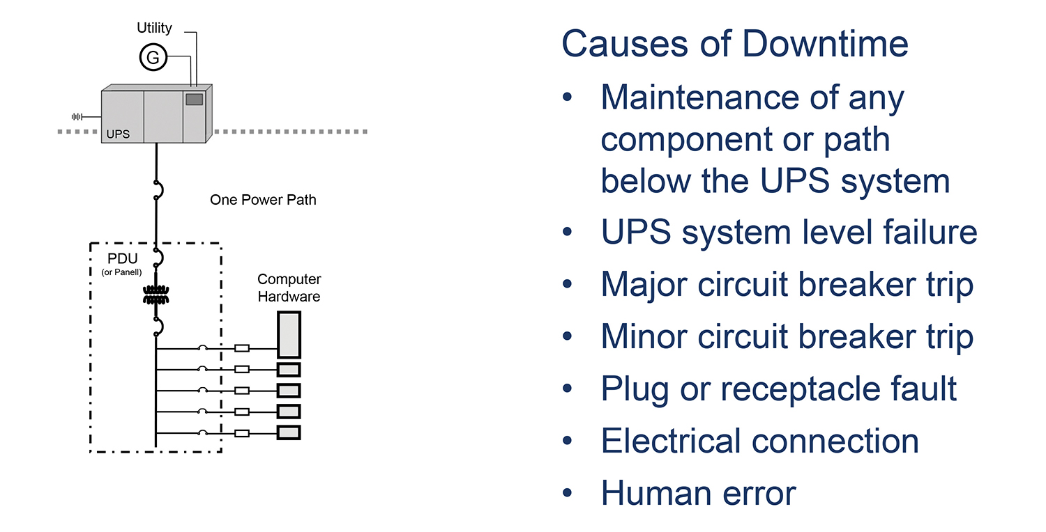
Figure 1. Single-corded IT equipment
Present
The Fault Tolerant Power Compliance Specification, Version 2.0 is clearly relevant 12 years later. Originally called Fault Tolerant IT devices, today the commonly used vernacular is dual corded, and these devices have become the basis of high availability. The two terms Fault Tolerant IT devices and dual-corded IT device are used interchangeably.
Tier III and Tier IV data centers designs continue to be based upon the use of dual-corded architecture and require an active-active, dual-path distribution. The dual-corded concept is cemented into high-availability architecture in enterprise data centers, hyper-scale internet providers, and third-party data center spaces. Even the innovative Open Compute Project, sponsored by Facebook, which uses cutting-edge electrical architecture, utilizes dual-corded, Fault Tolerant IT devices.
Confoundingly, though, more than half of the more than 5,000 reported incidents in the Uptime Institute Network’s Abnormal Incident Reports (AIRs) database relate to the critical distribution system.
Dual-corded assets have increased maintenance opportunities for data center facilities management. Operations teams no longer need to wait for inconveniently timed maintenance windows to perform maintenance; instead they can maintain their facilities without IT impact during safe and regular hours. If there is an anomaly, the facilities and IT staff are on hand to address them.
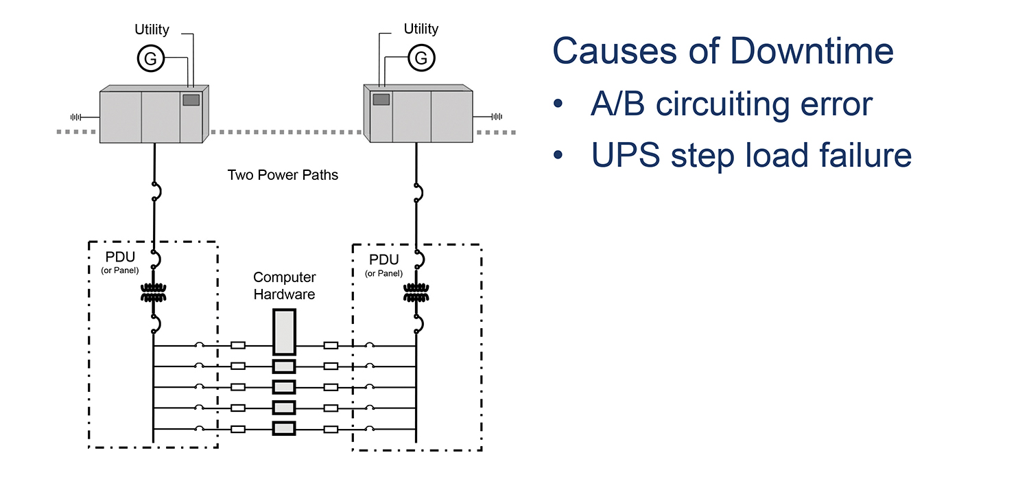
Figure 2. Fault-Tolerant-and-dual-corded
Uptime Institute Network members today recognize the benefits of dual-corded devices. COO Jason Weckworth of RagingWire recently said, “Dual-corded IT devices allow RagingWire the maintenance and operations flexibility that are consistent with our Concurrently Maintainable objective and provide that extra level of availability assurance below the UPS system where any problem may have consequential impacts to availability.”
Uptime Institute Network adoption of dual-corded devices has clearly improved, as indicated by the number of outages attributed to critical distribution. Properly applied, dual-corded devices do not experience any effect on loss of a single source. Analysis of the AIRs database from 2007 to 2012 showed a reduction of more than 90% of critical distribution failures impacting the IT load.
Some data center owners or IT teams try to achieve dual power paths to IT equipment using large static transfer switches (STS) or STS power distribution units (PDU) (see Figure 3). However, problems inherent in the maintenance, replacement, or a fault of an STS for the device and onward threaten the critical load. One data center suffered a fault on an STS-PDU that affected one third of its IT equipment and loss of those systems rendered the entire data center unavailable. As noted in Figure 3, the single large STS solution does not meet Tier III or Tier IV criteria.
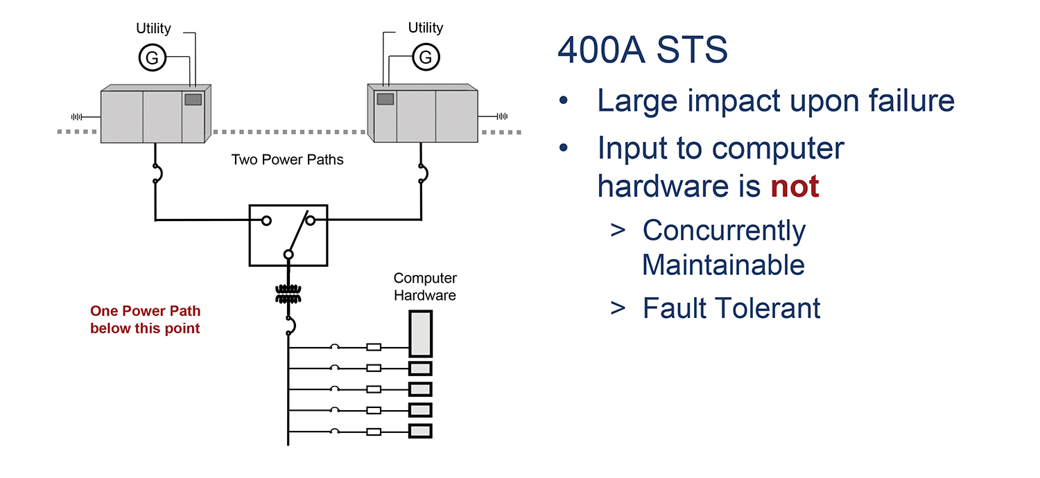
Figure 3. Static transfer switches
Uptime Institute recognizes that some heritage devices or legacy systems may end up in data centers, due to systems migrations challenges, mergers and acquisitions, consolidations, or historical clients. Data center infrastructure professionals need to question the justifications that lead to these conditions: If the system is so important, why is it not migrated to a high-availability, dual-corded IT asset?
The Tier Standard: Topology does include an accommodation for single-corded equipment as shown in Figure 4, depicting a local, rack-mounted transfer switch. The rack-mounted or point-of-use transfer switch allows for distribution of risk as low as possible in the critical distribution.
Still, many in IT have not yet gotten the message and bring in more than the occasional one-off device. Single-corded devices are found in a larger percentage of installations than should be expected. Rob McClary, SVP and GM of FORTRUST, said, “FORTRUST utilizes infrastructure with dual-power paths, yet we estimate that greater than 50% of our clients continue to deploy at least one or more single-corded devices that do not utilize our power infrastructure and could impact their own availability. FORTRUST strongly supports continued education to our end user community to utilize all dual-corded IT assets for a true high-availability solution.” The loss of even one of the data centers asset in their deployment can render the platforms or applications of the deployment unavailable. The disconnect between data center infrastructure and IT hardware continues to exist.
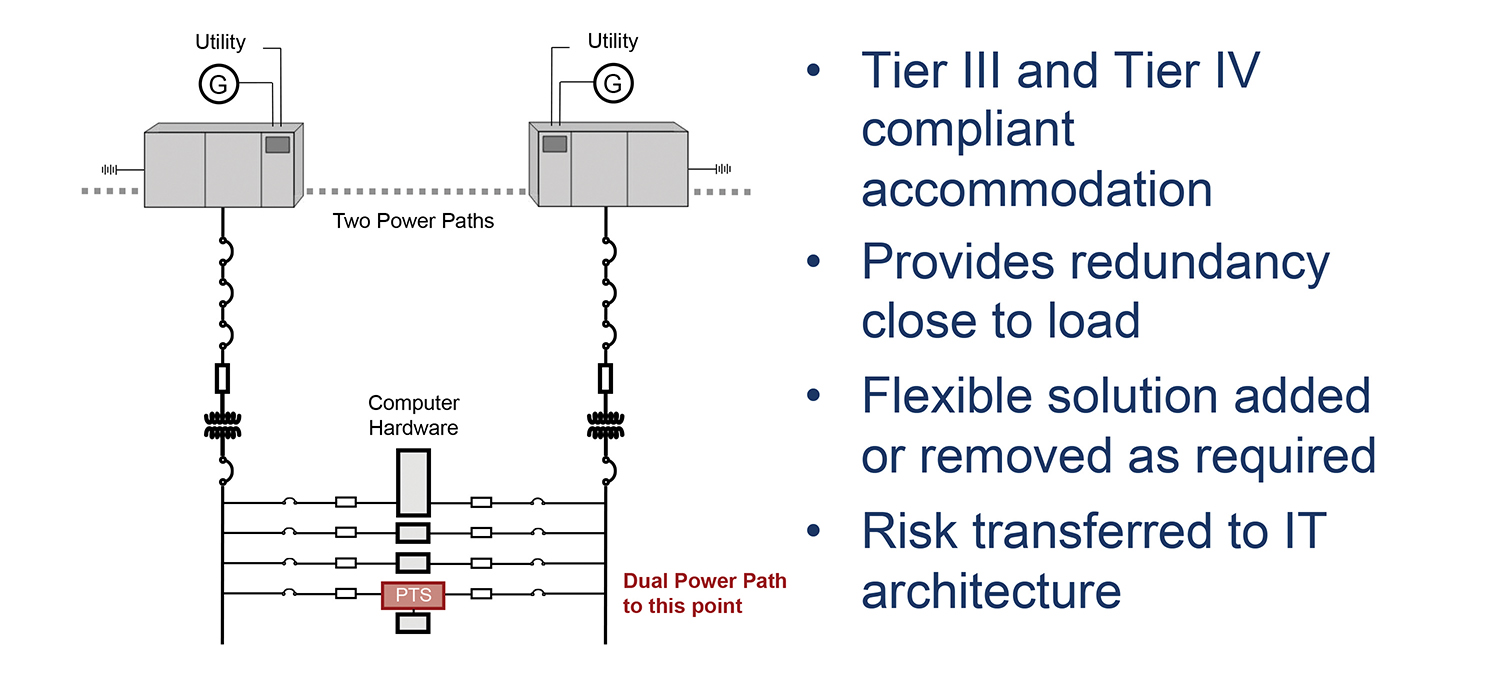
Figure 4. Point-of-use transfer switch
Uptime Institute teams still find the following configurations that continue to plague data center operators:
- Single-corded network devices
- Mainframes that degrade or are lost on loss of a single source of power
- IT devices with an odd number of cords
The Future: A Call to Action
Complex systems such as data center infrastructure and the IT equipment and systems within them require comprehensive team approaches to management, which means breaking down the barriers between the organizations by integrating Facilities and IT staff, allowing the integrated organization to manage the data center and educating end users who don’t understand power infrastructure. If we can’t integrate, then educate.
If a merger of IT and facilities just won’t work in an enterprise data center, a regular meeting will at least enable teams to share knowledge and review change management and facilities maintenance actions. In addition, codifying change management and maintenance window procedures in terms IT can understand using an ITIL-based system will enable IT counterparts to start to understand the criticality of power distribution as they see the how and why of data center facility operations firsthand.
Colocation and third-party data centers understand that many client IT organizations have limited in-house staff, expertise, and familiarity with high-availability data centers. The need to educate these clients is clear. Several ways to educate include:
- Compile incident reports involving single-corded device and share them with new tenants and deployments teams
- Create a one-page fact sheet on dual-corded infrastructure with a schematic and benefits summary that those users can understand
- Create a policy that requires rack-mounted or point-of-use transfer switches for all single-corded device.
- Require all devices that support a high-availability application or IT deployment to be dual corded
These actions will pay dividends with increased ease of maintenance and reduced client coordination.
Facilities teams also need to look within themselves. Improved monitoring and data center infrastructure management (DCIM) solutions provide windows into the infrastructure but do not replace good management. Anecdotal evidence has shown 1-10% of servers in a data center may be improperly corded, i.e., both cords are plugged into the A distribution.
Management can address these challenges by
- Clearly and consistently labeling A and B power
- Training all staff working in critical areas about data center policies, including the dual-corded policy
- Performing quality control to verify A/B cording, phase balancing, and installation documentation
- Capturing the configuration of the data center
- Regularly tracking single-corded installations to pressure owners of those systems to modernize
Summary
Millions of dollars are regularly invested in the dual-power path infrastructure in data centers for high availability because of business needs. This is clearly represented in the increasing cost of downtime from lost business to ruined reputations or goodwill. It is essential that Facilities and IT, including the procurement and installation teams, work together to safeguard the investment, making sure dual-power path technology is utilized for business critical applications. In addition, owners and operators of data centers must continue to educate customers who lack the knowledge or familiarity with data center practices and manage the data center to ensure high-availability principals such as dual-corded architecture are fully utilized.
Fault-Tolerant Power Compliance Specification Version 2.0
Fault-tolerant power equipment refers to computer or communication hardware that is capable of receiving AC input from two different AC power sources. The objective is to maintain full equipment functionality when operating from A and B power sources or from A alone or from B alone. Equipment with an odd number of external power inputs (line cords) generally will not meet this requirement. It is desirable for equipment to have the least number of external power inputs while still meeting the requirement for receiving AC input from two different AC power sources. Products requiring more than two external power inputs risk being rejected by some sites. For equipment to qualify as truly fault-tolerant power compliant, it must meet all of the following criteria as initially installed, at ultimate capacity, and under any configuration or combination of options. (The designation of A and B power sources is used for clarity in the following descriptions.)
- If either one of two AC power sources fails or is out-of-tolerance, the equipment must still be able to start up or continue uninterrupted operation with no loss of data, reduction in hardware functionality, performance, capacity, or cooling.
- After the return of either AC power source from a failed or out-of-tolerance condition, during which acceptable power was continuously available from the other AC power source, the equipment will not require a power-down, IPL, or human intervention to restore data, hardware functionality, performance, or capacity.
- The first or second AC power source may then subsequently fail no later than 10 seconds after the return of the first or second AC power source from a failed or out-of-tolerance condition with no loss of data, reduction in hardware functionality, performance, capacity, or cooling.
- The two AC power sources can be out of synchronization with each having a different voltage, frequency, phase rotation, and phase angle as long as the power characteristics for each separate AC source remain within the range of the manufacturer’s published specifications and tolerances.
- Both external AC power inputs must terminate within the manufacturer’s fault-tolerant power compliant computer equipment. In the event that the external AC power input is a detachable power cord, the equipment must provide for positive retention of the female plug so the plug cannot be pulled loose accidentally. Within the equipment, the AC power train (down to and including the AC to DC power supplies) must be compartmentalized such that any power train component to neighter side can be safely serviced without affecting computer equipment availability or performance and without putting the AC power train of the other side at risk.
- For single- or three-phase power sources, the neutral conductor in the AC power input shall not be bonded to the chassis ground inside the equipment. This will prevent circulating ground currents between the two external power sources.
- Internal or external active AC input switching devices (e.g., mechanical or electronic transfer switches) are not acceptable.
- A fault inside the manufacturer’s equipment that results in the failure of one AC power source shall not be transferred to the second AC power source causing it to also fail.
- For single- or three-phase power sources, with both AC power inputs available and with both inputs operating at approximately the same voltage, the normal load on each power source will be shared within 10% of the average.
- For three-phase power source configurations, the normal load on each phase will be within 10% of the average.
 Keith Klesner’s career in critical facilities spans 14 years and includes responsibilities ranging from planning, engineering, design and construction to start-up and ongoing operation of data centers and mission-critical facilities. In the role of Uptime Institute vice president of Engineering, Mr. Klesner has provided leadership and strategic direction to maintain the highest levels of availability for leading organizations around the world. Mr. Klesner performs strategic-level consulting engagements, Tier Certifications and industry outreach—in addition to instructing premiere professional accreditation courses. Prior to joining the Uptime Institute, Mr. Klesner was responsible for the planning, design, construction, operation and maintenance of critical facilities for the U.S. government worldwide. His early career includes six years as a U.S. Air Force officer. He has a Bachelor of Science degree in Civil Engineering from the University of Colorado-Boulder and a Masters in Business Administration from the University of LaVerne. He maintains status as a professional engineer (PE) in Colorado and is a LEED-accredited professional.


 2020
2020


