Diesel exhaust after treatment for data centers
Cleaning up your act: A guide to exhaust standards
By Lamont Fortune, PE, United Health Group
Are your diesel generators used strictly for emergency or non-emergency purposes? Your answer to this question will tell you just how clean your diesel exhaust has to be by 2015 (and as early as 2014) as far as the U.S. Environmental Protection Agency (EPA) is concerned. Of course, you may have already run into this issue.
The EPA is thinking about your diesel exhaust because of the air pollution regulations spelled out in the EPA Standards of Performance for Stationary Compression Ignition Internal Combustion Engines (CI ICE) from 40CFR (Code of Federal Regulations), Part 60, Subpart IIII. The EPA air pollution regulations are very extensive, including a completely separate standard for spark ignition engines. The air quality requirements for engine generator exhaust emissions regulated by this document were first declared effective on September 11, 2006. The regulations have undergone some revisions and updates since then due to industry objections. The last final revision was released on January 14, 2013. This six-plus-year period has seen active industry involvement in an attempt to better balance the overall environmental benefit with regulation adoption and enforcement.
CI ICE in the Data Center Arena
EPA 40CFR, Part 60, Subpart IIII covers CI ICE powered by liquid, gaseous, and solid fuels and built from 2007 forward. This particular article, however, focuses strictly on the compliance needs of diesel-fueled engines. EPA 40CFR, Part 60, Subpart IIII sets up four primary engine characteristics to determine what emission source restrictions must be observed and when. These characteristics are as follows:
1. Classification
2. Model year manufactured (not shipped or delivered)
3. Cylinder displacement
4. Horsepower
These characteristics are part of an elaborate and layered matrix with compliance categories tiers, which was designed to guide the overall industry implementation of these air quality standards from Day One 2007 through January 1, 2015.
In turn, these standards included a targeted and continual incremental reduction of allowed emissions of four pollutant groups during engine operation. The lowest and final permitted discharge levels take effect on January 1, 2015.
Now in its seventh year of implementation, the current (2013) compliance program has evolved so that Tier 4 Interim and Tier 4 Final are the only remaining categories. The four targeted pollutant groups are:
1. Nitrogen oxides
2. Particulate matter
3. Carbon monoxide
4. Non-methane hydrocarbons
Both engine manufacturers and end users are responsible for working together to achieve operational compliance. Manufacturers have to build increasingly clean burning engines; end users have to purchase the correct EPA Tier-certified engine to install (either EPA Tier 4 Interim or EPA Tier 4 Final at this point) and the appropriate engine exhaust after treatment (see Figure 1).
Emissions control is a joint effort of the end user and the engine generator vendor.
Since no single after treatment effectively reduces all four pollutant groups, a combination of methods is needed to meet mandated targets. Consequently, the only way EPA Tier 4 Final compliance can be verified is by field testing the generator and its after-treatment system. As a side note, all of these requirements for diesel engine generators are applied in conjunction with the current use of ultra-low sulfur diesel fuel (less than or equal to 15-ppm sulfur content) as part of the EPA’s multi-pronged approach to achieving clean air.
So now that you know about the EPA’s emission limitations for CI ICE, how do they apply to your situation? Let’s go back to the opening question to start to answer that: Are your diesel generators used strictly for emergency or non-emergency purposes?
Emergency or Non-Emergency?
If your generators are used solely for emergency purposes, 40CFR, Part 60, Subpart IIII does not apply. In this case, emergency means that your generators are operated for emergency backup power only when there is an electrical utility outage. Therefore, generators installed for fire and life-safety purposes also fall within the emergency designation. In addition, generators used to power critical networks and equipment can qualify as long as they are operated only during times of electric utility loss. And fire and flood pump applications also fall squarely in the emergency status camp, whether powered by engine generator or direct engine drive.
If, however, the chosen operational strategy is to run CI ICE for any other purpose when utility power is available (such as storm avoidance), then non-emergency status applies, and the application must comply with 40CFR, Part 60, Subpart IIII. This status also applies if there is a standing financial incentive or arrangement (peak shaving, demand response, rate curtailment, continuous base loading, etc.) for a generator operator to supply power into an electric utility grid for the grid owner’s benefit.
Regardless of whether the engine generators involved are permanently installed or rental units for temporary use (i.e., non-road mobile), 40 CFR, Part 60, Subpart IIII still applies.
EPA regulations recognize the practical need for maintaining the reliability of the backup system, including emergency utility requests for disconnection from their grid to sustain grid stability in avoiding brownouts, blackouts and utility islanding. The EPA does allow emergency equipment to be run for system maintenance, exercising and testing purposes, up to 100 hours per year. Non-emergency equipment subject to 40CFR, Part 60, Subpart IIII regulations can be run typically up to 50 hours per year for these purposes. Allowable runtimes, though, may be less than these numbers, depending on the local air district authority having jurisdiction (AHJ).
Figure 2 shows the EPA Tier 4 compliance timeline for various sizes of non-emergency engine generators. Please also understand that once an after-treatment system has been successfully installed and commissioned detailed system operating records need to be maintained from that point forward. Besides being useful from a practical operating perspective, these records then document ongoing compliance with EPA’s air quality standards.
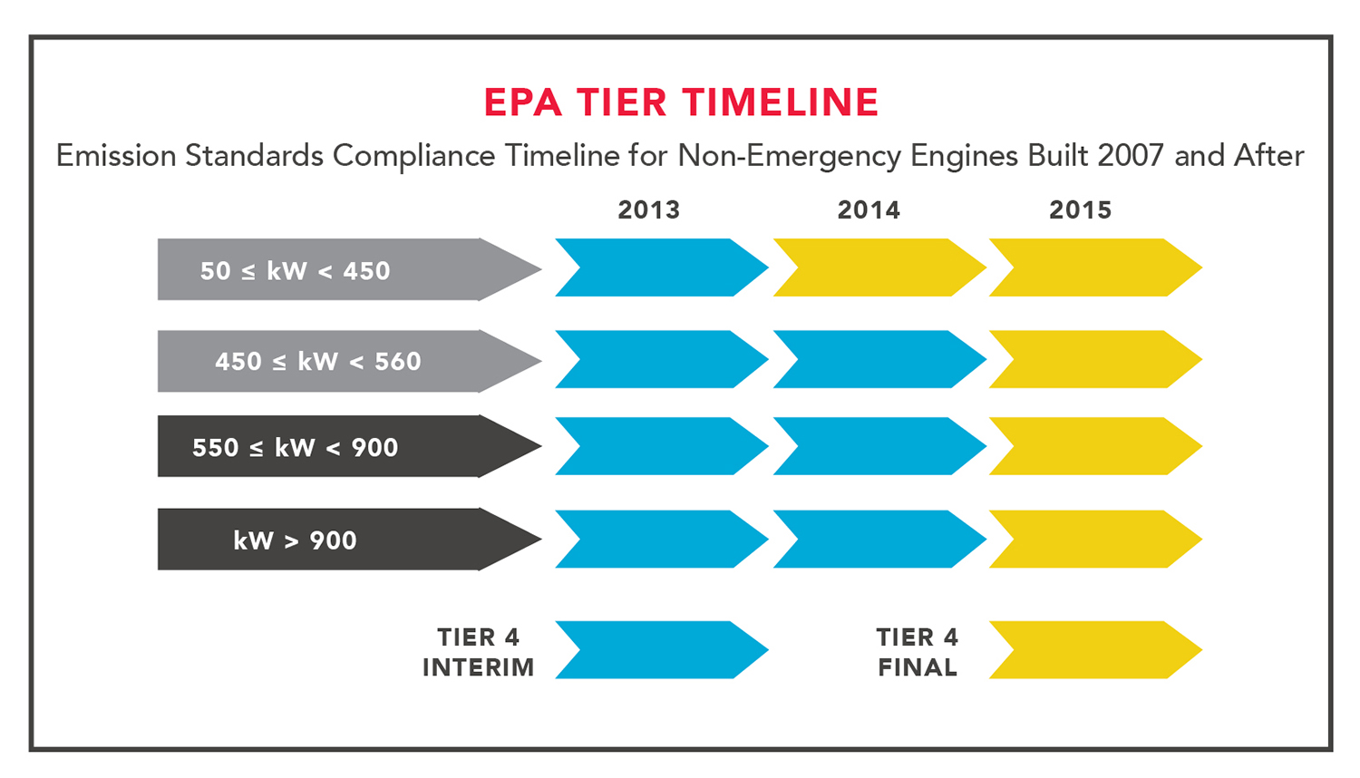
EPA compliance timeline.
After-Treatment Systems
After-treatment systems basically come in either proprietary prepackaged forms or as custom-located and interconnected components. Either way, the prevailing design approach is that each engine has its own dedicated after-treatment system. These use a reactant-based treatment in combination with stationary catalyst elements. The reactant is typically a 32.5-wt% urea solution (known generically in the U.S. as diesel exhaust fluid or DEF and in Europe as AdBlue or AUS 32), a 40-wt% solution, or an ammonia solution. While ammonia can be used as a reactant, urea is preferred because it is much less toxic, easier to transport and store and simpler to permit.
Platinum, palladium, copper zeolite, iron zeolit, and Vanadia are common catalysts. The contact geometries for the catalyst elements are often of a honeycomb type but vary by system manufacturer. Catalyst elements are not intended to be thought of or act as particulate filters.
Each of the major engine manufacturers is currently promoting its own after-treatment system to accompany and mate with its respective engine products, apparently in an effort to keep after-treatment packages in as compact an arrangement as possible to minimize the floor and/or cubic space required to house them. Nonetheless, be prepared to need a significant amount of room in addition to that normally used by the engine generator. Serviceability and maintainability also become important design issues to consider when evaluating the various options for after-treatment systems.
Figure 3 is a diagram of a fairly generic urea after-treatment system offered by one major supplier of such systems. Note that the preliminary treatment equipment is shown without the external insulation that will be required for safety and operational efficiency reasons for a final installation.
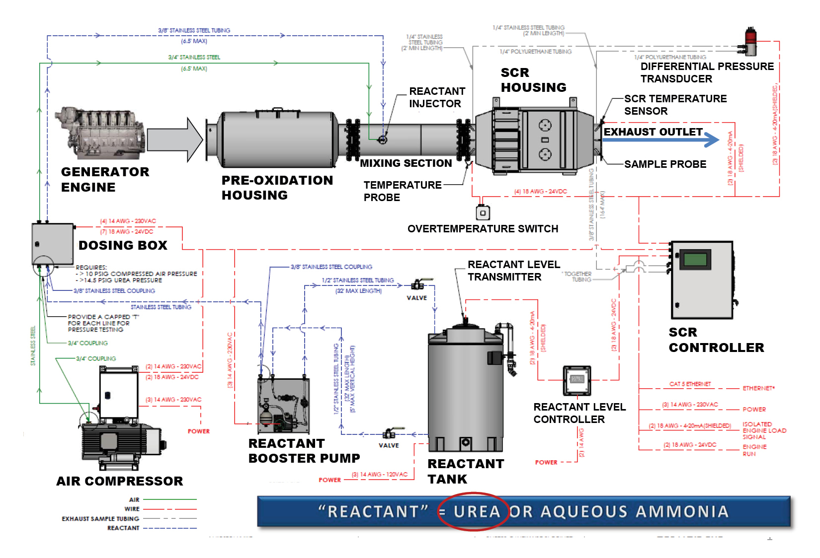
After-treatment system diagram
Exhaust gases from an EPA Tier 4-certified engine are directed through a pre-oxidation catalyst section to a reactant mixing section and then finally on to a selective catalytic reduction (SCR) unit before being discharged to the outside atmosphere. The precious metal catalyst materials in the pre-oxidation unit significantly reduce carbon monoxide, non-methane hydrocarbons and other hazardous air pollutants from the exhaust including up to 50% of the particulate matter. Urea then gets injected into and thoroughly mixed with the pre-oxidation output gases after the temperature of these gases rises to the 300-400°C (572-752°F) range before subsequent introduction into the SCR unit. This urea activation temperature is needed to actively regenerate the SCR catalyst as well as incinerate any accumulated ash. Passive and slower rate regeneration, however, occurs prior to this activation temperature being reached. (Note: Some SCR systems activate urea injection at 93°F [200°C].) And lastly, the SCR unit is where the bulk (up to 90%) of the remaining nitrogen oxides is removed before final discharge to the atmosphere.
The remaining components shown (reactant storage tank, booster pump, air compressor, dosing box and SCR controller) are all to support the correct operation of the overall after treatment. They represent the dynamic parts of the system whereas the pre-oxidation and SCR units are the static components. The SCR controller serves as the brains of the system in directing the necessary urea injection rates to achieve required discharge emission targets.
One side benefit of the after-treatment system is that it provides acoustical attenuation of the engine-generator noise that has normally been handled by an exhaust silencer. In fact, an acoustical analysis could show that a traditional silencer is not needed because the after-treatment system will fulfill the necessary sound reduction needs.
An After-Treatment System Example
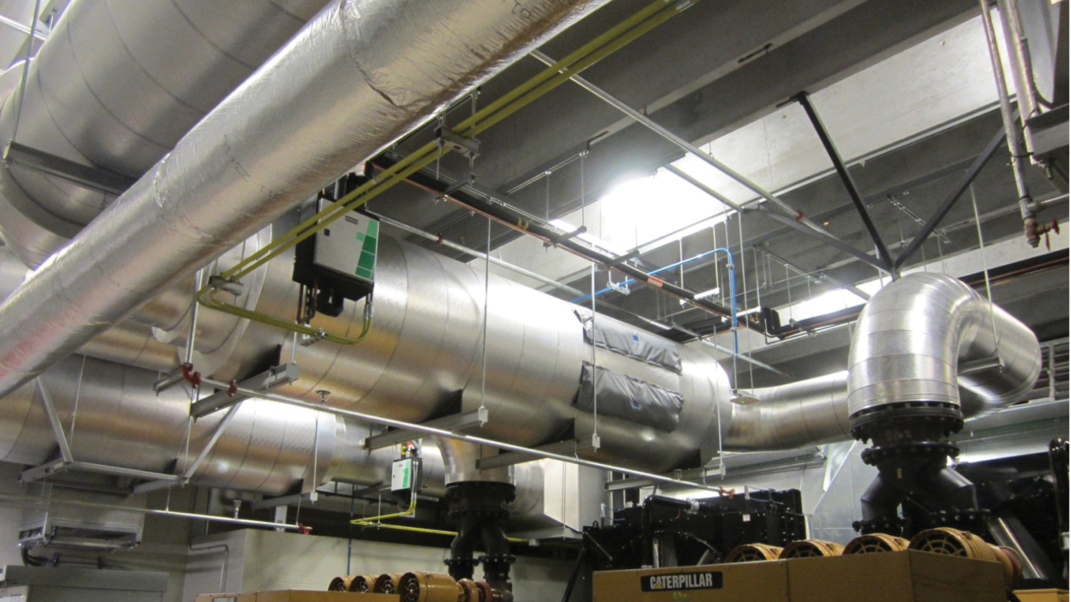
The next set of figures (See Figures 4-10) depicts an actual installation of the generic after-treatment system previously described for a 2.725-megawatt (MW) generator driven by a 4005-HP prime-rated engine. They also convey some sense of the amount of additional cubic space required to accommodate such a system.
The surfaces of the catalyst modules that the exhaust gases flow across in this section (See Figure 4) should be visually checked for ash deposits every few years depending on the intensity of engine use during that time. These catalyst modules can be removed, swept clean of ash (using appropriate safety gear and associated practices), re-oriented to expose clean surfaces and then reinstalled. There is no need to replace the catalyst modules themselves.
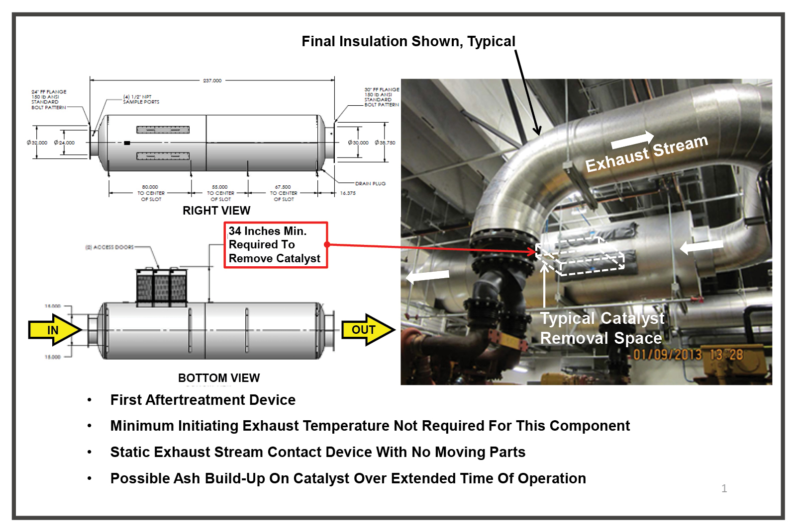
Oxidation catalyst housing
Although the mixing section itself (See Figure 5) is basically a static unit with no moving parts, it is specifically engineered from a dimensional perspective to promote maximal mixing of injected urea with the engine exhaust gas stream given the engine’s discharge flow parameters. The combination of flow turbulence produced by the static mixers and atomized urea injection into the exhaust flow are integral to producing thorough mixing.
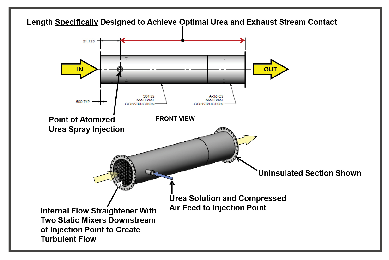
Illustration shows the urea injection and mixing section.
Figure 6 gives a more detailed view of the urea-dosing box and how it interfaces with the point of atomized urea spray injection. And although the various equipment components of a generic after-treatment system can be custom located, there can be limits on the maximum distances between components. Figure 6 shows one such limit: how far the dosing box can be from the urea injection point is shown.
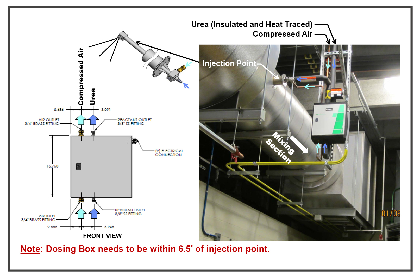
The dosing box is a critical part of the mixing process.
The urea dose rate adjustment occurs in the dosing box, based on control feedback from the SCR controller. The compressed air feed is responsible for producing a very fine atomization of the liquid (or aqueous) urea flow for optimal injection and mixing efficiency. Both flows must work together for effective performance.
The heat of the mixed exhaust stream then evaporates the urea content and causes it to decompose into ammonia before this exhaust stream enters the SCR housing.
The urea supply line in this case is heat traced and insulated to ensure reliable flow operation during engine runtimes for the coldest expected winter days. Maintaining urea quality and fluidity within its recommended temperature range is critical to keep the injection spray nozzle from clogging with crystalline deposits and, thus, preventing adequate after treatment.
The final key after-treatment step occurs next within the SCR housing unit (see Figure 6), which is where the nitrogen oxide content of the exhaust stream gets knocked down to levels that comply with the EPA’s Tier 4 mandate. The intimate mixture of evaporated urea turned to ammonia entering the exhaust chemically reacts with the catalyst elements within the SCR housing to effect the conversion of the remaining nitrogen oxides into mostly nitrogen (N2), CO2 and water for discharge to the atmosphere. Some minute amounts of ammonia (called ammonia slip) may also sneak through the SCR housing and exit with the intended discharge products. Proper tuning of the urea dosing to the actual installed system performance conditions, however, will minimize ammonia slip issues.
As a reminder, the SCR housing shown in Figure 7 is for a 2.725-MW system. The installed unit with final insulation for this size system requires a 7-foot clearance from the underside of the supporting structure. Because of the width of the housing, a fire sprinkler head is required underneath. This head and accompanying sprinkler piping in turn take up even more height. Consequently, careful planning, unit placement, and overall adequate room height are needed for a successful installation that can be safely accessed and serviced.
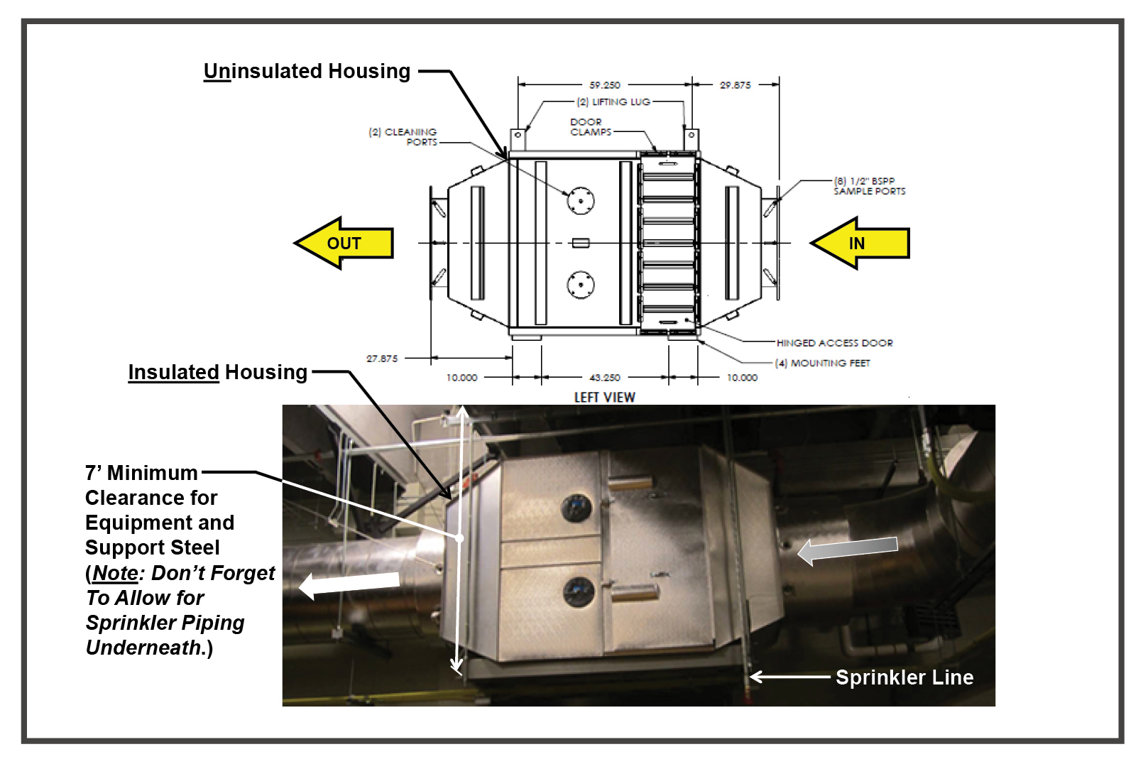
Components have maximum and minimum clearances.
SCR technology, by the way, has been successfully used for nitrogen oxide removal for decades, having started out in central power plant applications for the exhausts of gas turbines and reciprocating engines. Therefore, this technology will likely continue to be around for a long time to meet future emissions standards as well.
Figure 8 illustrates the types of operating characteristics monitored for the SCR unit. These include the differential pressure across the SCR housing, inlet and outlet temperatures and a continuous sampling port for the final exhaust gas. They each have status indication connections with the SCR controller so the controller can regulate the upstream urea dosing and overall system operation to provide the required after-treatment results. All things considered, SCR unit monitoring is relatively straightforward.
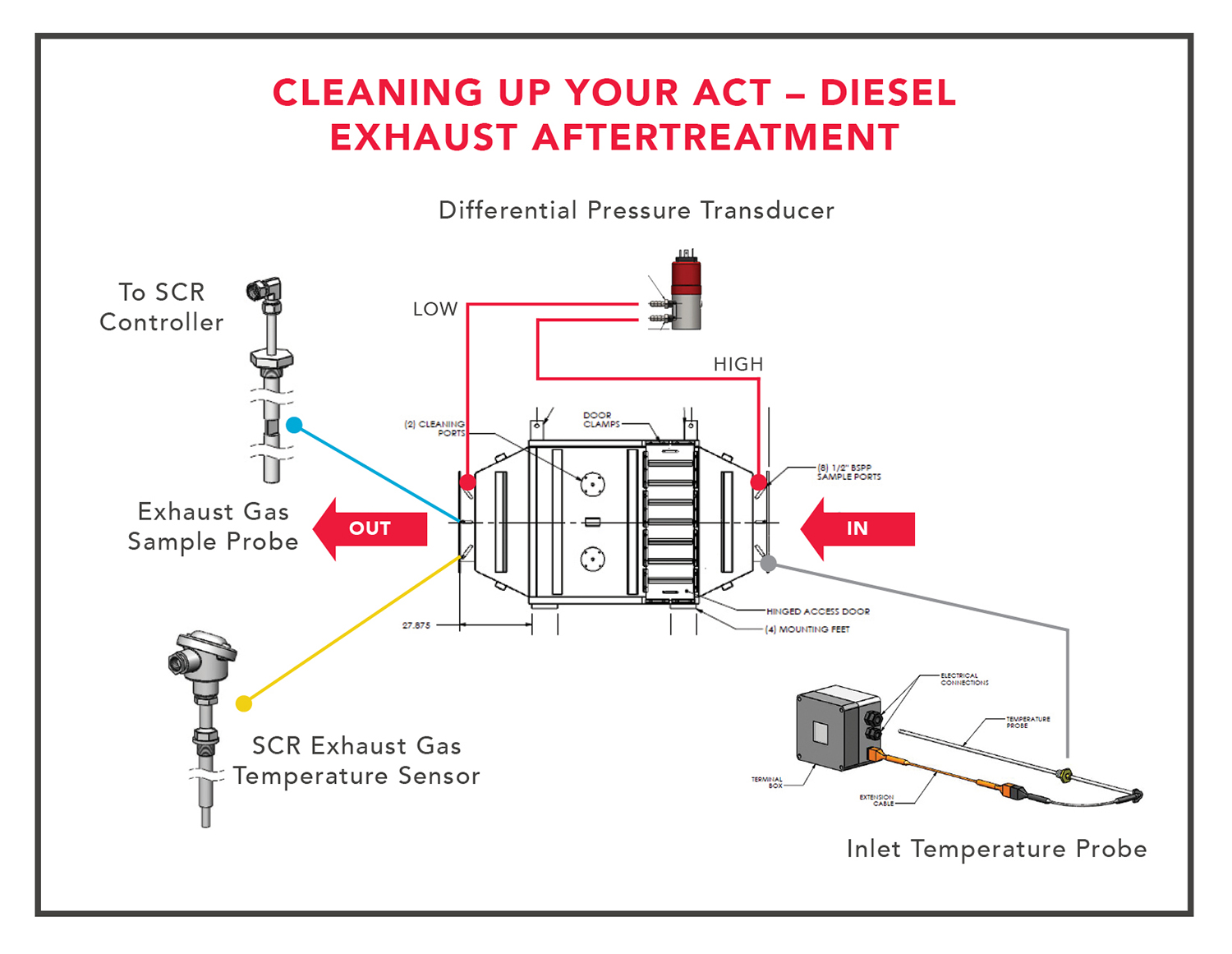
Key operating parameters to be monitored include include differential pressure,
inlet and outlet temperatures and final exhaust gas quality.
Figure 9 shows a room full of SCR controllers. This is the technical complexity of the after-treatment-system lies. Though there is a sample port in the discharge of the SCR unit, the actual gas sampling operation happens within the SCR controller. Each controller housing contains a nitrogen oxide comparison cell, little pumps, fans, fine filters and small cooling equipment as well as a touchscreen-activated programmable controller for each after-treatment system. This includes operating set points, status monitoring, performance parameter indications, diagnostics, alarm generation, maintenance alerts and other historical data records.
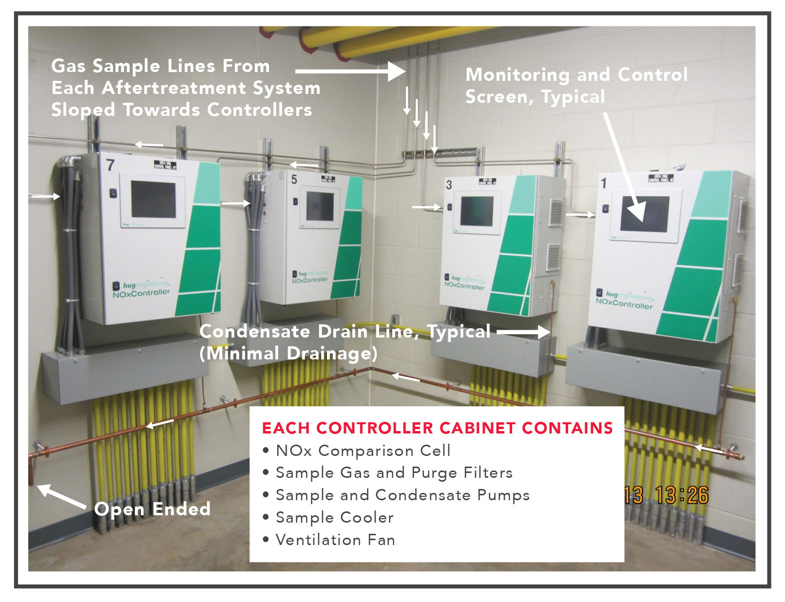
A room full of SCR controllers.
Figure 10 shows a large-scale central urea storage and distribution system. Using high-quality aqueous urea (solid urea dissolved in water) and sustaining its quality throughout its storage life are essential for effective after-treatment system performance. To start, the solid urea used to make aqueous urea needs to be of commercial-or technical-grade purity (99.45% pure). Next, the water used to make 32.5-wt% aqueous urea solutions (40 wt% is also used for some systems) also has to be ultra clean, such as the product of reverse osmosis or ion exchange cartridges. These purification requirements remove as many potential catalyst poisons as possible. The list of catalyst poisons contains at least 31 elements, most of them heavy metals and compounds containing silicon (Si), phosphorous (P), arsenic (As), antimony (Sb), sodium (Na), and zinc (Zn). Fortunately, ready-made aqueous urea solutions meeting necessary purification standards can be commercially purchased for nominally around US$3 per gallon, often from a fuel oil supplier.
Things to Know About Aqueous Urea
Make sure you and your urea solution supplier use caution in transporting and handling this solution to avoid any contamination from its exposure to other materials or environments. Once safely stored on-site, the next task is to keep the solution between 32-77°F (25-30°C). At 32°F (25°C) and lower, the solution will begin to stratify and form precipitates, which will form deposits in the storage tanks. In addition, the solution concentration will become inconsistent and no longer perform reliably after treatment. Aqueous urea freezes and crystallizes at 12°F (-11°C), and solution temperatures above 77°F (25°C) (and especially above 86°F [(30°C]) accelerate solution breakdown. Therefore, the temperature range restrictions point to the technical requirements for the necessary environmental conditions for effective storage and distribution of aqueous urea.
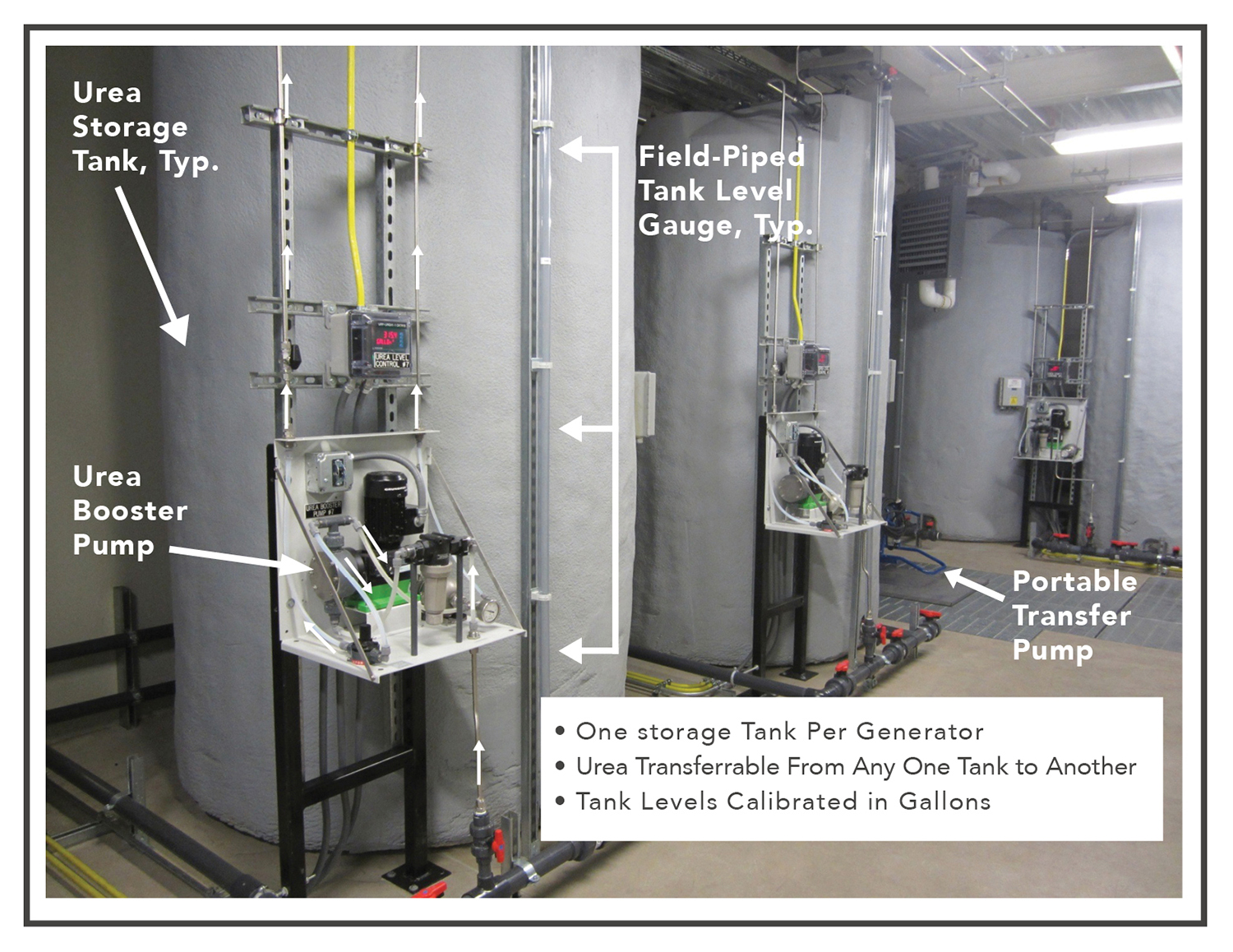
A large-scale central storage and distribution system.
The materials within the urea storage and distribution system likewise play an important role in helping to maintain solution purity. For example, stainless steels (304, 304L, 316, and 316L), polyethylene, polypropylene and polyisobutylene are recommended for direct contact applications. Other plastics such as PFE, PTFE, PFA and PVDF are also acceptable. All plastics considered should be free of additives. On the opposite end of the compatibility spectrum, carbon steel, galvanized steel, copper, copper alloys, aluminum, lead and zinc are not recommended for direct contact uses. Solders containing silver, lead, zinc and copper are also not recommended.
Urea as a solid material is available in different grades and is used in making fertilizers, cosmetics, food additives and industrial processes. Aqueous urea can also be used as a fertilizer, which may be a disposal option depending on local regulations. It is a clear and colorless liquid with a specific gravity of 1.09. It is non-flammable and readily biodegradable, with no known significant hazardous properties–even at a pH between 9.0 and 9.8. Nonetheless, personnel handling urea should use goggles and rubber gloves.
So what is a reasonable shelf life for aqueous urea? Figure 11 is a table that shows shelf life as a function of storage temperature. As the storage temperature rises, the expected urea shelf life drops. This inverse relationship (six-month shelf life change for every 9°F [13°C] change) is a key reason why prolonged storage above 77°F (25°C) (and especially above 86°F [30°C]) is not a recommended practice.
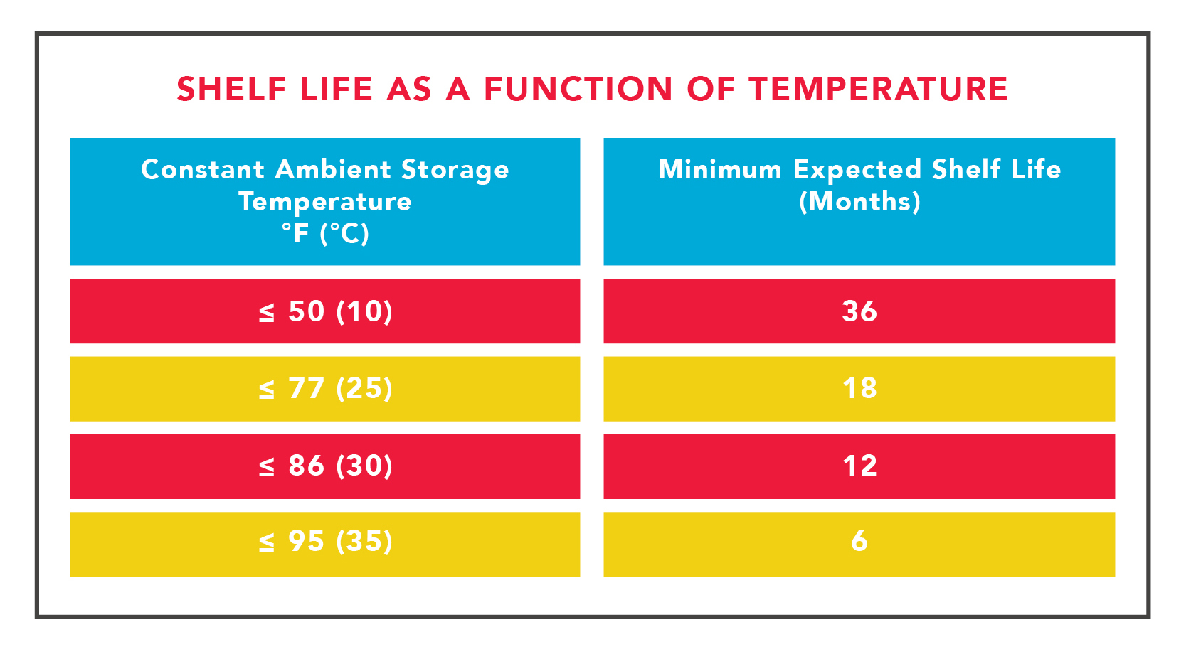
Urea shelf life as a function of temperature.
Another good shelf-life management practice is to periodically sample and test the urea solution quality. ISO 22241 probably comes closest to being the national or international sampling standard. That said, the following would be a recommended monitoring practice:
1. Determine the initial (or latest) as-received shipment of aqueous urea alkalinity as NH3 as the starting baseline predictor of quality condition for that shipment.
2. Choose a time interval (six months, three months, monthly, etc.) for urea quality control checks based on expected usage.
3. Trend subsequent quality check results by continuing to measure urea alkalinity of each sample as NH3 to track the change of this value.
4. Use ISO 22241-2 parameters as the complete set of reference characteristics for judging urea quality conditions.
Lessons Learned
At this point, we have covered the basic design and installation of an engine exhaust after-treatment system and maybe a smidge of some operational considerations. Actual operating experience, however, of almost two years has brought me additional insight into predictive factors.
After-treatment systems have to reach internal temperatures 600°F (316°C) of nominal before any urea solution injection will be initiated. With an installation having engines that produce 817°F (436°C) exhaust temperatures only when they are running flat out at 100% load, a single exercising engine could activate urea use with relative ease by powering a load bank set for about 70% or higher engine loading. However, if this installation involves multiple engines running in a redundant configuration, hitting the initiation temperature becomes much harder to achieve without some clever manipulation. And even clever manipulation may not be enough to achieve an activation scenario depending on the active mix of the following:
1. Overall building load (move-in, fully loaded, in-between)
2. Minimum number of generators needed to run to keep total harmonic distortion on the building electrical distribution system within acceptable limits
3. Load bank conditions (permanent, temporary and capacity relative to a single generator, etc.)
4. The various operating configurations employed (i.e., emergency, non-emergency, maintenance, exercising, etc.)
The design expectation based on manufacturer technical literature for effective after treatment was for six gallons of urea to be used for every 100 gallons of fuel oil. The operating reality is that this ratio is more like 1.9 gallons of urea per 100 gallons of fuel oil, or 32% of originally predicted. This reality then begs the following issues for further scrutiny:
1. The original design numbers were based on engines running at 100% load. In a highly redundant normal operating configuration (N+2 minimum), each engine generator operates partly loaded with that partial load depending on the actual overall demand load at a point in time and the number of engines running. That demand load can shift depending upon the operating scenario. Therefore, the original design assumptions not only did not match actual operating conditions, they grossly overestimated them for most of these scenarios by a factor of three.
2. This overestimation, in turn, translates into oversized urea storage facilities and the purchase of too much urea, at least initially. Having too much urea on-hand leads to storing urea to the limits of its expected shelf life or beyond.
3. The minimum individual engine loading to create hot enough exhaust temperatures to initiate urea injection is 70%. While this loading was first determined during the commissioning phase, full realization of its consequences, unfortunately, took much longer to arrive.
4. Engine-generator operation during monthly exercising activities requires a permanently installed load bank to insure urea injection. This condition, however, is the only one of several where urea injection can be achieved.
5. Exercising an engine under no-load conditions for any length of time usually results in incomplete combustion within the engine. This, in turn, causes the discharge of partially combusted fuel oil by-products into the exhaust and, therefore, the downstream after-treatment system. The fouling in this situation (affectionately called slobber by some) is certainly not good for the internal surfaces (including the precious metal impregnated ones) of the after-treatment system.
6. Operating records indicate that the normal non-exercise operation scenario typically imposes a 45% load on each engine generator, well below that required to initiate urea injection. This, unfortunately, is inherent to running a highly redundant configuration.
7. There seems to be no current consensus on what should be done if normal operation of an engine-generator system does not produce hot enough exhaust temperatures to initiate urea injection into its after-treatment system. Will enforcement of 40CFR, Part 60, Subpart IIII be such that owners should expect frequent assessment of penalty fees for non-compliance? Will such no-urea-injection operating results mean that backup systems cannot be legally operated? Will lower-than-needed activation temperatures for urea injection be acceptable? Will the Best Available Control Technology (BACT) standard be invoked by the EPA to address this apparent disconnect between after-treatment functional goals and the BACT to allow additional time to come up with a workable solution? Will backup power requirements needed to meet Uptime Institute Tier Standards be affected?
So caveat emptor (buyer beware), especially if a highly redundant engine-generator system is involved. A new design and operation challenge is now before the mission critical data center community!
Cost Awareness
The installed cost of the after-treatment system described in this article for ten 2.725 MW units was about US$4.5 million, with only US$2,500 being spent for urea in the first year of operation. Contracted maintenance service costs, however, are much healthier and shown in Figure 12.
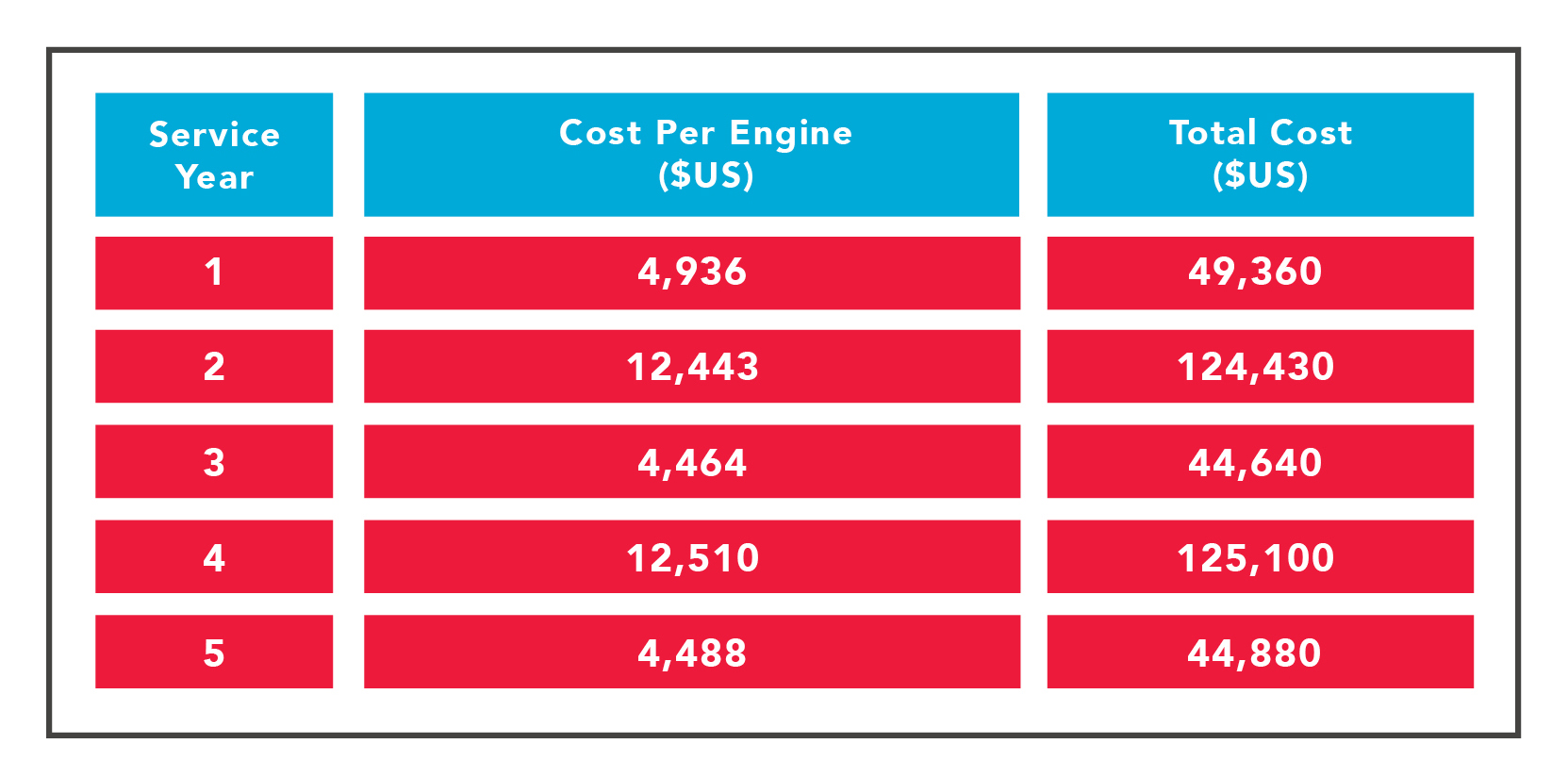
Contracted maintenance service costs for a typical system comprising ten
2.725-MW units.
These costs are based on an annual maintenance visit and a more thorough alternating bi-annual visit. They do demonstrate the importance of careful consideration of maintenance cost.
NESHAP
Now that the EPA requirements for engines made in 2007 and after have been discussed, attention should be turned to those engine-generator installations with engines manufactured in 2006 and earlier. These installations do not get to avoid EPA regulations. They just have to comply with another long-named reference standard instead (40CFR, Part 63, Subpart ZZZZ). These regulations are known as the EPA National Emission Standards for Hazardous Air Pollutants for Reciprocating Internal Combustion Engines (or NESHAP for RICE for short).
Though less stringent than 40CFR, Part 60, Subpart IIII, NESHAP still will likely require the installation of an oxidation catalyst unit on the exhaust of each engine to meet the newer and much stricter carbon monoxide (CO) emission targets than those that had previously existed. In fact, there are already combination silencer and oxidation catalyst housings available that can often be installed in the same location as existing silencers to minimize retrofit problems. These CO targets vary according to engine horsepower rating, hazardous air pollutant source potential-to-emit (either Area or Major), and the same Emergency and Non-Emergency engine classifications as previously described for 40CFR, Part 60.
Conclusion
Backup diesel engine generators are integral to most modern data centers. And engine-generator use varies depending on the business mission, criticality, and sophistication of a particular data center. The EPA and regional air quality districts have long since pegged engine generators as unfavorable but necessary air emissions polluting sources, typically restricting their annual runtime allowances to 100 hours or less.
The individual impact of this campaign for a data center depends on how the data center uses its engine generator(s). If the use is for emergency purposes only, then the prevailing emission standards are less restrictive. If nothing else, an oxidation catalyst installation may (or may not) be in your near future. Many new and emerging data center projects are claiming emergency status to avoid the added costs and complexities of installing exhaust after-treatment systems.
Nonetheless, if intended generator use does include non-emergency use, then expect to get very familiar with exhaust after-treatment systems. The content of this article is meant to assist that familiarization so your air emissions act can get appropriately cleaned up. Uptime Institute Tier III and higher projects are more likely candidates for falling into the non-emergency category.
In conclusion, currently operating data centers and new data centers due to come online need to understand their vulnerability to EPA and regional air quality district regulations. Evaluating this potential impact hinges on a host of factors discussed within this article, including some lessons learned from a real-life operating after-treatment system. While the technology for legitimate after-treatment systems is fairly mature, its use within the data center world is not. Therefore, let the growing pains begin—and with knowledgeable foresight and guidance, let them quickly be absorbed and abated. Uninterruptible uptime is about to get a lot cleaner.
Lamont Fortune, PE , is the lead mechanical engineer in the Data Center Facilities group within the Information Technology division of UnitedHealth Group (or UHG-IT). He has over 40 years of engineering experience in the facility infrastructure field involving water and wastewater treatment plants, high production printing, corporate offices, research laboratories, archival record storage and other technical operations. His last 20-plus years have been especially focused on mission-critical data center projects including their planning, design, project management, construction, commissioning and operations. These projects have ranged across the private, institutional, governmental and military arenas. He enjoys addressing the complexities of successfully sustaining uninterruptible uptime environments.


 2019
2019

