A Look at Data Center Cooling Technologies
Sabey optimizes air-cooled data centers through containment
By John Sasser
The sole purpose of data center cooling technology is to maintain environmental conditions suitable for information technology equipment (ITE) operation. Achieving this goal requires removing the heat produced by the ITE and transferring that heat to some heat sink. In most data centers, the operators expect the cooling system to operate continuously and reliably.
I clearly recall a conversation with a mechanical engineer who had operated data centers for many years. He felt that most mechanical engineers did not truly understand data center operations and design. He explained that most HVAC engineers start in office or residential design, focusing on comfort cooling, before getting into data center design. He thought that the paradigms they learn in those design projects don’t necessarily translate well to data centers.
It is important to understand that comfort cooling is not the primary purpose of data center cooling systems, even though the data center must be safe for the people who work in them. In fact, it is perfectly acceptable (and typical) for areas within a data center to be uncomfortable for long-term occupancy.
As with any well-engineered system, a data center cooling system should efficiently serve its function. Data centers can be very energy intensive, and it is quite possible for a cooling system to use as much (or more) energy as the computers it supports. Conversely, a well-designed and operated cooling system may use only a small fraction of the energy used by ITE.
In this article, I will provide some history on data center cooling. I will then discuss some of the technical elements of data center cooling, along with a comparison of data center cooling technologies, including some that we use in Sabey’s data centers.
The Economic Meltdown of Moore’s Law
In the early to mid-2000s, designers and operators worried about the ability of air-cooling technologies to cool increasingly power hungry servers. With design densities approaching or exceeding 5 kilowatts (kW) per cabinet, some believed that operators would have to resort to technologies such as rear-door heat exchangers and other kinds of in-row cooling to keep up with the increasing densities.
In 2007, Ken Brill of the Uptime Institute famously predicted the Economic Meltdown of Moore’s Law. He said that the increasing amount of heat resulting from fitting more and more transistors onto a chip would reach an endpoint at which it would no longer be economically feasible to cool the data center without significant advances in technology (see Figure 1).
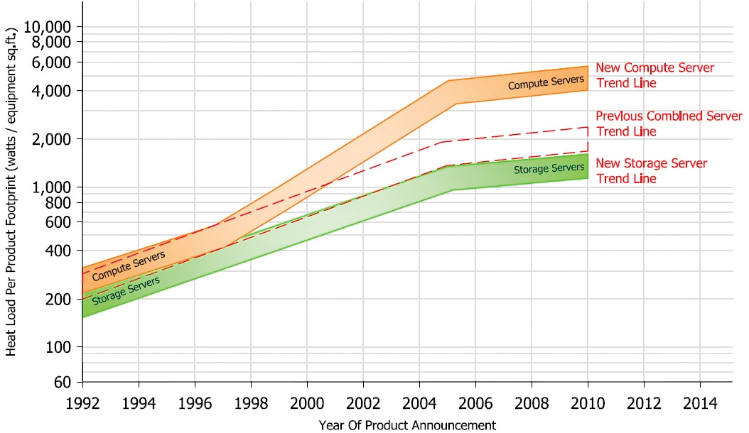
Figure 1. ASHRAE New Datacom Equipment Power Chart, published February 1, 2005
The U.S. Congress even got involved. National leaders had become aware of data centers and the amount of energy they require. Congress directed the U.S. Environmental Protection Agency (EPA) to submit a report on data center energy consumption (Public Law 109-341). This law also directed the EPA to identify efficiency strategies and drive the market for efficiency. This report projected vastly increasing energy use by data centers unless measures were taken to significantly increase efficiency (see Figure 2).
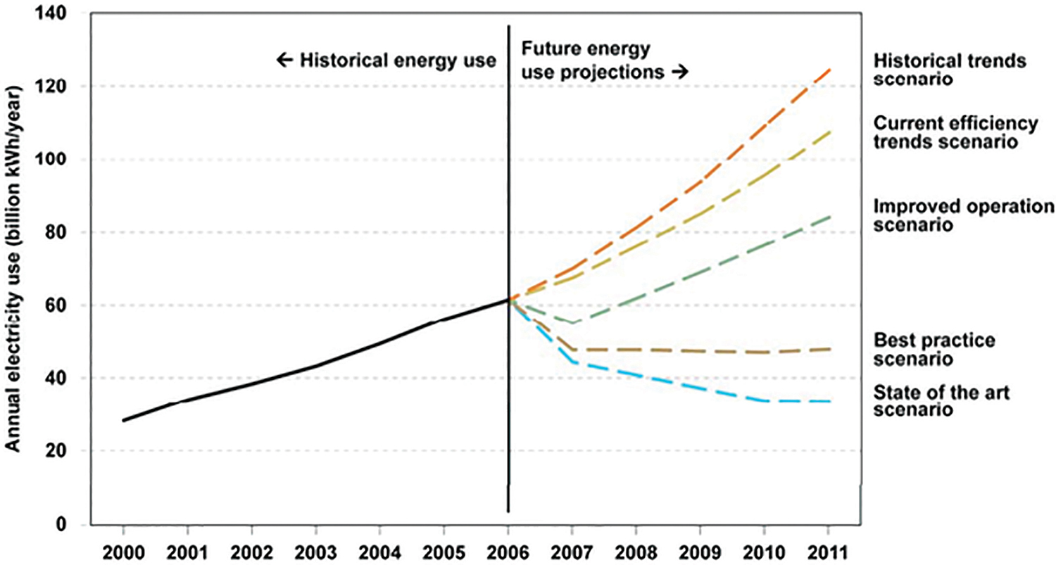
Figure 2. Chart ES-1 from EPA report dated (August 2, 2007)
As of 2014, Moore’s Law has not yet failed. When it does, the end will be a result of physical limitations involved in the design of chips and transistors, having nothing to do with the data center environment.
At about the same time that EPA published its data center report, industry leaders took note of efficiency issues, ITE manufacturers began to place a greater emphasis on efficiency in their designs, in addition to performance; and data center designers and operators began designing for efficiency as well as reliability and cost; and operators started to realize that efficiency does not require a sacrifice of reliability.
Legacy Cooling and the End of Raised Floor
For decades, computer rooms and data centers utilized raised floor systems to deliver cold air to servers. Cold air from a computer room air conditioner (CRAC) or computer room air handler (CRAH) pressurized the space below the raised floor. Perforated tiles provided a means for the cold air to leave the plenum and enter the main space—ideally in front of server intakes. After passing through the server, the heated air returned to the CRAC/CRAH to be cooled, usually after mixing with the cold air. Very often, the CRAC unit’s return temperature was the set point used to control the cooling system’s operation. Most commonly the CRAC unit fans ran at a constant speed, and the CRAC had a humidifier within the unit that produced steam. The primary benefit of a raised floor, from a cooling standpoint, is to deliver cold air where it is needed, with very little effort, by simply swapping a solid tile for a perforated tile (see Figure 3).
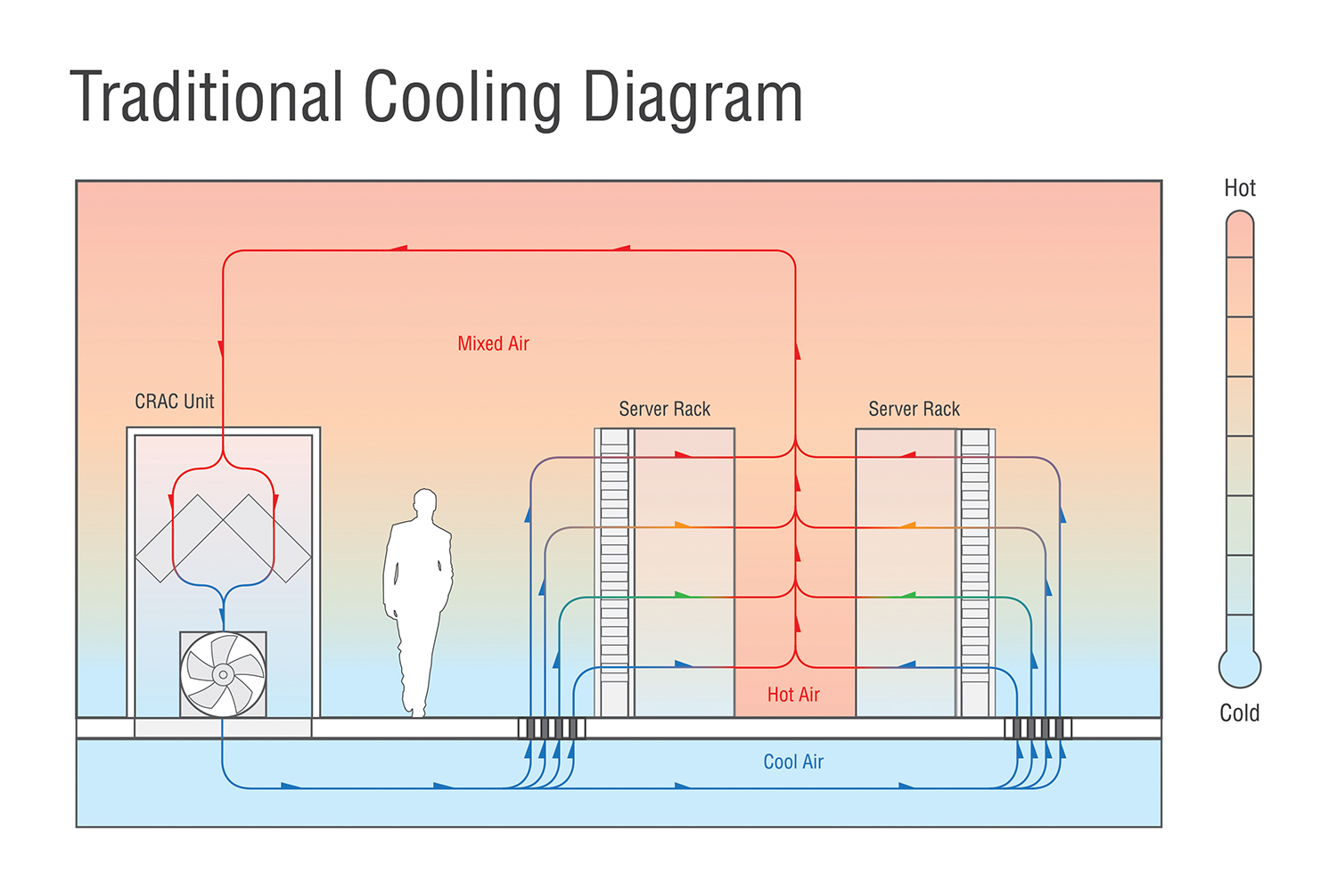
Figure 3: Legacy raised floor cooling
For many years, this system was the most common design for computer rooms and data centers. It is still employed today. In fact, I still find many operators who are surprised to enter a modern data center and not find raised floor and CRAC units.
The legacy system relies on one of the principles of comfort cooling: deliver a relatively small quantity of conditioned air and let that small volume of conditioned air mix with the larger volume of air in the space to reach the desired temperature. This system worked okay when ITE densities were low. Low densities enabled the system to meet its primary objective despite its flaws—poor efficiency, uneven cooling, etc.
At this point, it is an exaggeration to say the raised floor is obsolete. Companies still build data centers with raised floor air delivery. However, more and more modern data centers do not have raised floor simply because improved air delivery techniques have rendered it unnecessary.
How Cold is Cold Enough?
“Grab a jacket. We’re going in the data center.”
Heat must be removed from the vicinity of the ITE electrical components to avoid overheating the components. If a server gets too hot, onboard logic will turn it off to avoid damage to the server.
ASHRAE Technical Committee 9.9 (TC 9.9) has done considerable work in the area of determining suitable environments for ITE. I believe their publications, especially Thermal Guidelines for Data Processing Equipment, have facilitated the transformation of data centers from the “meat lockers” of legacy data centers to more moderate temperatures. [Editor’s note: The ASHRAE Technical Committee TC9.9 guideline recommends that the device inlet be between 18-27°C and 20-80% relative humidity (RH) to meet the manufacturer’s established criteria. Uptime Institute further recommends that the upper limit be reduced to 25°C to allow for upsets, variable conditions in operation, or to compensate for errors inherent in temperature sensors and/or controls systems.]
It is extremely important to understand that the TC 9.9 guidelines are based on server inlet temperatures—not internal server temperatures, not room temperatures, and certainly not server exhaust temperatures. It is also important to understand the concepts of Recommended and Allowable conditions.
If a server is kept too hot, but not so hot that it turns itself off, its lifespan could be reduced. Generally speaking, this lifespan reduction is a function of the high temperatures the server experiences and the duration of that exposure. In providing a broader Allowable range, ASHRAE TC 9.9 suggests that ITE can be exposed to the higher temperatures for more hours each year.
Given that technology refreshes can occur as often as every 3 years, ITE operators should consider how relevant the lifespan reduction is to their operations. The answer may depend on the specifics of a given situation. In a homogenous environment with a refresh rate of 4 years or less, the failure rate of increased temperatures may be insufficient to drive cooling design—especially if the manufacturer will warrant the ITE at higher temperatures. In a mixed environment with equipment of longer expected life spans, temperatures may warrant increased scrutiny.
In addition to temperature, humidity and contamination can affect ITE. Humidity and contamination tend to only affect ITE when the ITE is exposed to unacceptable conditions for a long period of time. Of course, in extreme cases (if someone dumped a bucket of water or dirt on a computer) one would expect to see an immediate effect.
The concern about low humidity involves electro-static discharge (ESD). As most people have experienced, in an environment with less moisture in the air (lower humidity), ESD events are more likely. However, ESD concerns related to low humidity in a data center have been largely debunked. In “Humidity Controls for Data Centers – Are They Necessary” (ASHRAE Journal, March 2010), Mark Hydeman and David Swenson wrote that ESD was not a real threat to ITE, as long as it stayed in the chassis. On the flip side, tight humidity control is no guarantee of protection against ESD for ITE with its casing removed. A technician removing the casing to work on components should use a wrist strap.
High humidity, on the other hand, does appear to pose a realistic threat to ITE. While condensation should definitely not occur, it is not a significant threat in most data centers. The primary threat is something called hygrometric dust particles. Basically, higher humidity can make dust in the air more likely to stick to electrical components in the computer. When dust sticks, it can reduce heat transfer and possibly cause corrosion to those components. The effect of reduced heat transfer is very similar to that caused by high temperatures.
There are several threats related to contamination. Dust can coat electronic components, reducing heat transfer. Certain types of dust, called zinc whiskers, are conductive. Zinc whiskers have been most commonly found in electroplated raised floor tiles. The zinc whiskers can become airborne and land inside a computer. Since they are conductive, they can actually cause damaging shorts in tiny internal components. Uptime Institute documented this phenomenon in a paper entitled “Zinc Whiskers Growing on Raised-Floor Tiles Are Causing Conductive Failures and Equipment Shutdowns.”
In addition to the threats posed by physical particulate contamination, there are threats related to gaseous contamination. Certain gases can be corrosive to the electronic components.
Cooling Process
The cooling process can be broken into steps:
1. Server Cooling. Removing heat from ITE
2. Space Cooling. Removing heat from the space housing the ITE
3. Heat Rejection. Rejecting the heat to a heat sink outside the data center
4. Fluid Conditioning. Tempering and returning fluid to the white space, to maintain appropriate
conditions within the space.
Server Cooling
ITE generates heat as the electronic components within the ITE use electricity. It’s Newtonian physics: the energy in the incoming electricity is conserved. When we say a server uses electricity, we mean the server’s components are effectively changing the state of the energy from electricity to heat.
Heat transfers from a solid (the electrical component) to a fluid (typically air) within the server, often via another solid (heat sinks within the server). ITE fans draw air across the internal components, facilitating this heat transfer.
Some sytems make use of liquids to absorb and carry heat from ITE. In general, liquids perform this function more efficiently than air. I have seen three such sytems:
• Liquid contact with a heat sink. A liquid flows through a server and makes contact with a heat sink inside the equipment, absorbing heat and removing it from the ITE.
• Immersion cooling. ITE components are immersed in a non-conductive liquid. The liquid absorbs the heat and transfers it away from the components.
• Dielectric fluid with state change. ITE components are sprayed with a non-conductive liquid. The liquid changes state and takes heat away to another heat exchanger, where the fluid rejects the heat and changes state back into a liquid.
In this article, I focus on systems associated with air-cooled ITE, as that is by far the most common method used in the industry.
Space Cooling
In legacy data center designs, heated air from servers mixes with other air in the space and eventually makes its way back to a CRAC/CRAH unit. The air transfers its heat, via a coil, to a fluid within the CRAC/CRAH. In the case of a CRAC, the fluid is a refrigerant. In the case of a CRAH, the fluid is chilled water. The refrigerant or chilled water removes the heat from the space. The air coming out of the CRAC/CRAH often has a discharge temperature of 55-60°F (13-15.5°C). The CRAC/CRAH blows the air into a raised floor plenum—typically using constant-speed fans. The standard CRAC/CRAH configuration from many manufacturers and designers controls the unit’s cooling based on return air temperature.
Layout and Heat Rejection Options
While raised floor free cooling worked okay in low-density spaces where no one paid attention to efficiency, it could not meet the demands of increasing heat density and efficiency—at least not as it had been historically used. I have been in legacy data centers with temperature gauges, and I’ve measured temperatures around 60°F (15.5°C) at the base of a rack and temperatures near 80°F (26°C) at the top of the same rack and also calculated PUEs well in excess of two.
People began to employ best practices and technologies including Hot Aisles and Cold Aisles, ceiling return plenums, raised floor management, and server blanking panels to improve the cooling performance in raised floor environments. These methods are definitely beneficial, and operators should use them.
Around 2005, design professionals and operators began to experiment with the idea of containment. The idea is simple; use a physical barrier to separate cool server intake air from heated server exhaust air. Preventing cool supply air and heated exhaust air from mixing provides a number of benefits, including:
• More consistent inlet air temperatures
• The temperature of air supplied to the white space can be raised, improving options for efficiency
• The temperature of air returning to the coil is higher, which typically makes it operate more efficiently
• The space can accommodate higher density equipment
Ideally, in a contained environment, air leaves the air handling equipment at a temperature and humidity suitable for ITE operation. The air goes through the ITE only once and then returns to the air handling equipment for conditioning.
Hot Aisle Containment vs. Cold Aisle Containment
In a Cold Aisle containment system, cool air from air handlers is contained, while hot server exhaust air is allowed to return freely to the air handlers. In a Hot Aisle containment system, hot exhaust air is contained and returns to the air handlers, usually via a ceiling return plenum (see Figure 4).
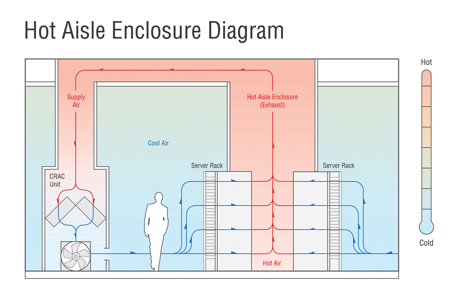
Figure 4: Hot Aisle containment
Cold Aisle containment can be very useful in a raised floor retrofit, especially if there is no ceiling return plenum. In such a case, it might be possible to leave the cabinets more or less as they are, as long as they are in a Cold Aisle/Hot Aisle arrangement. One builds the containment system around the existing Cold Aisles.
Most Cold Aisle containment environments are used in conjunction with raised floor. It is also possible to use Cold Aisle containment with another delivery system, such as overhead ducting. The raised floor option allows for some flexibility; it is much more difficult to move a duct, once it is installed.
In a raised floor environment with multiple Cold Aisle pods, the volume of cold air delivered to each pod depends largely on the number of floor tiles deployed within each of the containment areas. Unless one builds an extremely high raised floor, the amount of air that can go to a given pod is going to be limited. High raised floors can be expensive to build; the heavy ITE must go on top of the raised floor.
In a Cold Aisle containment data center, one must typically assume that airflow requirements for a pod will not vary significantly on a regular basis. It is not practical to frequently switch out floor tiles or even adjust floor tile dampers. In some cases, a software system that uses CFD modeling to determine airflows based on real time information can then control air handler fan speeds in an attempt to get the right amount of air to the right pods. There are limits to how much air can be delivered to a pod with any given tile configuration; one must still try to have about the right amount of floor tiles in the proper position.
In summary, Cold Aisle containment works best in instances where the designer and operator have confidence in the layout of ITE cabinets and in instances where the loading of the ITE does not change much, nor vary widely.
I prefer Hot Aisle containment in new data centers. Hot Aisle containment increases flexibility. In a properly designed Hot Aisle containment data center, operators have more flexibility in deploying containment. The operator can deploy a full pod or chimney cabinets. The cabinet layouts can vary. One simply connects the pod or chimney to the ceiling plenum and cuts or removes ceiling tiles to allow hot air to enter it.
In a properly controlled Hot Aisle containment environment, the ITE determines how much air is needed. There is a significant flexibility in density. The cooling system floods the room with temperate air. As air is removed from the cool side of the room by server fans, the lower pressure area causes more air to flow to replace it.
Ideally, the server room has a large, open ceiling plenum, with clear returns to the air handling equipment. It is easier to have a large, open ceiling plenum than a large, open raised floor, because the ceiling plenum does not have to support the server cabinets. The air handlers remove air from the ceiling return plenum. Sabey typically controls fan speed based on differential pressure (dP) between the cool air space and the ceiling return plenum. Sabey attempts to keep the dP slightly negative in the ceiling return plenum, with respect to the cool air space. In this manner, any small leaks in containment cause cool air to go into the plenum. The air handler fans ramp up or down to maintain the proper airflow.
Hot Aisle containment requires a much simpler control scheme and provides more flexible cabinet layouts than a typical Cold Aisle containment system.
In one rather extreme example, Sabey deployed six customer racks in a 6000 ft2 space pulling a little more than 35 kilowatts (kW) per rack. The racks were all placed in a row. Sabey allowed about 24 inches between the racks and built a Hot Aisle containment pod around them. Many data centers would have trouble accommodating such high density racks. A more typical utilization in the same space might be 200 racks (30 ft2 per rack) at 4.5 kW/rack. Other than building the pod, Sabey did not have to take any sort of custom measures for the cooling. The operations sequence worked as intended, simply ramping up the air handler fans a bit to compensate for the increased airflow. These racks have been operating well for almost a year.
Hot Aisle containment systems tend to provide higher volumes of conditioned air compared to Cold Aisle containment, which is a minor benefit. In a Cold Aisle containment system, the volume of air in a data center at any given time is the volume of air in the supply plenum (whether that is a raised floor or overhead duct) and the amount of air in the contained Cold Aisles. This volume is typically less than the volume in the remainder of the room. In a Hot Aisle containment system, the room is flooded with air. The volume of hot air is typically limited to the air inside the Hot Aisle containment and the ceiling return plenum.
Hot Aisle containment also allows operators to remove raised floor from the design. Temperate air floods the room, often from the perimeter. The containment prevents mixing, so air does not have to be delivered immediately in front of the ITE. Removing raised floor reduces the initial costs and the continuing management headache.
There is one factor that could lead operators to continue to install raised floor. If one anticipates direct liquid cooling during the lifespan of the data center, a raised floor may make a very good location for the necessary piping.
Close-Coupled Cooling
There are other methods of removing heat from white spaces, including in-row and in-cabinet solutions. For example, rear-door heat exchangers accept heat from servers and remove it from a data center via a liquid.
In-row cooling devices are placed near the servers, typically as a piece of equipment placed in a row of ITE cabinets. There are also systems that are located above the server cabinets.
These close-coupled cooling systems reduce the fan energy required to move air. These types of systems do not strike me as being optimal for Sabey’s business model. I believe such a system would likely be more expensive and less flexible than Hot Aisle containment layouts for accommodating unknown future customer requirements, which is important for Sabey’s operation. Close-coupled cooling solutions can have good applications, such as increasing density in legacy data centers.
Heat Rejection
After server heat is removed from a white space, it must be rejected to a heat sink. The most common heat sink is the atmosphere. Other choices include bodies of water or the ground.
There are various methods of transferring data center heat to its ultimate heat sink. Here is a partial list:
• CRAH units with water-cooled chillers and cooling towers
• CRAH units with air-cooled chillers
• Split system CRAC units
• CRAC units with cooling towers or fluid coolers
• Pumped liquid (e.g., from in-row cooling) and cooling towers
• Airside economization
• Airside economization with direct evaporative cooling (DEC)
• Indirect evaporative cooling (IDEC)
Economizer Cooling
Most legacy systems include some form of refrigerant-based thermodynamic cycle to obtain the desired environmental conditions. Economization is cooling in which the refrigerant cycle is turned off—either part or all of the time.
Airside economizers draw outside air into the data center, which is often mixed with return air to obtain the right conditions, before entering the data center. IDEC is a variation of this in which the outside air does not enter the data center but receives heat from the inside air via a solid heat exchanger.
Evaporative cooling (either direct or indirect) systems use evaporated water to supplement the availability of economizer cooling or more efficient refrigerant-based cooling. The state change of water absorbs energy, lowering the dry bulb temperature to a point where it approaches the wet bulb (saturated) temperature of the air (see Figure 5).
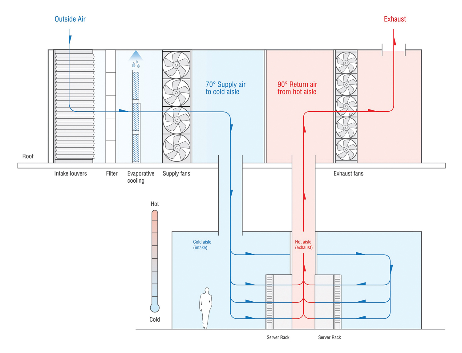
Figure 5. Direct evaporative cooling (simplified)
In waterside economizer systems, the refrigerant cycle is not required when outside conditions are cold enough to achieve the desired chilled water temperature set points. The chilled water passes through a heat exchanger and rejects the heat directly to the condenser water loop.
Design Criteria
In order to design a cooling system, the design team must agree upon certain criteria.
Heat load (most often measured in kilowatts) typically gets the most attention. Most often, heat load actually includes two elements: total heat to be rejected and the density of that heat. Traditionally, data centers have measured heat density in watts per square foot. Many postulate that density should actually be measured in kilowatts per cabinet, which is a very defensible in cases where one knows the number of cabinets to be deployed.
Airflow receives less attention than heat load. Many people use computational fluid dynamics (CFD) software to model airflow. These programs can be especially useful in non-contained raised floor environments.
In all systems, but especially in contained environments, it is important that the volume of air produced by the cooling system meet the ITE requirement. There is a direct relationship between heat gain through a server, power consumed by the server, and airflow through that server. Heat gain through a server is typically measured by the temperature difference between the server intake and server exhaust or delta T (∆T). Airflow is measured in volume over time, typically cubic feet per minute (CFM).
Assuming load has already been determined, a designer should know (or, more realistically, assume) a ∆T. If the designer does not assume a ∆T, the designer leaves it to the equipment manufacturer to determine the design ∆T, which could result in airflow that does not match the requirements.
I typically ask designers to assume a 20°F (11°C) ∆T. Higher density equipment, such as blades, typically has higher ∆T. However, most commodity servers are doing well to get as high as a 20°F (11°C) ∆T. (Proper containment and various set points can also make a tremendous difference.)
The risk of designing a system in which the design ∆T is lower than the actual ∆T is that the system will not be able to deliver the necessary airflow/cooling. The risk in going the other way is that the owner will have purchased more capacity than the design goals otherwise warrant.
The Design Day equals the most extreme outside air conditions the design is intended to handle. The owner and designers have to decide how hot is hot enough, as it affects the operation of the equipment. In Seattle, in the 100 years before July 29, 2009, there was not a recorded ambient temperature above 100°F (38°C) (as measured at SeaTac airport). Also keep in mind that equipment is often located (especially on the roof) where temperatures are higher than are experienced at official weather stations.
An owner must determine what the temperature and humidity should be in the space. Typically, this is specified for a Design Day when N equipment is operating and redundant units are off-line. Depending on the system, the designers will determine air handler discharge set points based on these conditions, making assumptions and/or calculations of temperature increases between the air handler discharge and the server inlet. There can be opportunities for more efficient systems if the owner is willing to go into the ASHRAE Allowable range during extreme outside temperatures and/or during upset conditions such as utility interruptions. Sabey typically seeks to stay within the ASHRAE Recommended range In its business model.
The owner and designer should understand the reliability goals of the data center and design mechanical, electrical, and controls to support these reliability goals. Of course, when considering these items, the design team may be subject to over building. If the design team assumes an extreme Design Day, adds in redundant equipment, specifies the low end of the ASHRAE Recommended range, and then maybe adds a little percentage on top, just in case, the resulting system can be highly reliable, if designed and operated appropriately. It can also be too expensive to build and inefficient to operate.
It is worth understanding that data centers do not typically operate at design load. In fact, during much of a data center’s lifespan, it may operate in a lightly loaded state. Operators and designers should spend some time making the data center efficient in those conditions, not just as it approaches design load. Sabey has made design choices that allow us to not only cool efficiently, but also to cool efficiently at light loads. Figure 6 shows that we reached average PUE conditions of 1.20 at only 10% loading at one of its operating data centers.
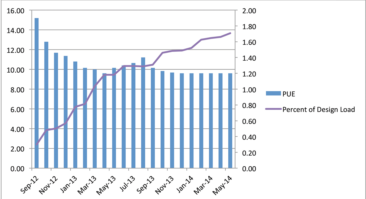
Figure 6. PUE and design load (%) over time.
Crystal Ball
While very high density ITE is still being built and deployed, the density of most ITE has not kept up with the increases projected 10 years ago. Sabey was designing data centers at an average 150 watts/ft2 6 years ago, and the company has not yet seen a reason to increase that. Of course, Sabey can accommodate significantly higher localized densities where needed.
In the near future, I expect air-based cooling systems with containment to continue to be the system of choice for cooling data centers. In the long term, I would not be surprised to see increasing adoption of liquid-cooling technologies.
Conclusion
Sabey Data Centers develops and operates data centers. It has customers in many different verticals and of many different sizes. As a service provider, Sabey does not typically know the technology or layout its customers will require. Sabey’s data centers use different cooling technologies, suitable to the location. Sabey has data centers in the mild climate of Seattle, the semi-arid climate of central Washington, and in downtown New York City. Sabey’s data centers are housed in single-story greenfield buildings and in a redeveloped high-rise.
Despite these variations and uncertainties, all the data centers Sabey designs and operates have certain common elements. They all use Hot Aisle containment without raised floor. All have a ceiling return plenum for server exhaust air and flood the room for the server inlet air. These data centers all employ some form of economizer. Sabey seeks to operate efficiently in lightly loaded conditions, with variable speed motors for fans, pumps, and chillers, where applicable.
Sabey has used a variety of different mechanical systems with Hot Aisle containment, and I tend to prefer IDEC air handlers, where practical. Sabey has found that this is a very efficient system with lower water use than the name implies. Much of the time, the system is operating in dry heat exchanger mode. The system tends to facilitate very simple control sequencing, and that simplicity enhances reliability. The systems restart rapidly, which is good in utility interruptions. The fans keep spinning and ramp up as soon as the generators start providing power. Water remains in the sump, so the evaporative cooling process requires essentially no restart time. Sabey has successfully cooled racks between 35-40 kW with no problem.
Until there is broad adoption of liquid-cooled servers, the primary opportunities appear to be in optimizing air-cooled, contained data centers.
John Sasser
John Sasser brings more than 20 years of management experience to the operations of Sabey Data Centers’ portfolio of campuses. In addition to all day-to-day operations, start-ups and transitions, he is responsible for developing the conceptual bases of design and operations for all Sabey data centers, managing client relationships, overseeing construction projects, and overall master planning.
Mr. Sasser and his team have received recognition from a variety of organizations, including continuous uptime awards from the Uptime Institute and energy conservations awards from Seattle City Light and the Association of Energy Engineers.
Prior to joining Sabey, he worked for Capital One and Walt Disney Company. Mr. Sasser also spent 7 years with the Navy Civil Engineer Corps.


