
New System Combats Data Center PQ Concerns
Using relevant technologies and techniques to develop an optimized system for addressing data center PQ concerns
By Kuochuan Chu
For years, engineers and data centers operators have implemented various strategies to improve power quality in mission-critical facilities. We have found, however, that good power quality requires a solid grounding system. By efficiently utilizing the essential power distribution component of a data center—the transformer, and properly applying phase-shift techniques, harmonic distortion problems can be resolved, significantly improving the overall energy efficiency of a computer room. For our grounding system, we used the structured color-codes management system, so that the power quality and grounding systems can be fully integrated, improving the overall performance and robustness of the data center infrastructure.
Good power quality is essential to reliable data center operation. Once power-related problems affect the overall infrastructure of a data center, the facility may fail, causing financial losses or interrupting years of research.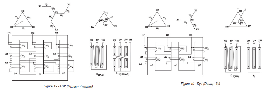
In recent years, our company planned, designed, and commissioned multiple data centers, and supported several research and development efforts. We also cooperated with manufacturers to develop products to improve overall power system performance and strengthen infrastructure management.
Relevant Research
IEEE Recommended Practice for Powering and Grounding Electronic Equipment (Emerald Book) notes that harmonic currents can cause alternating current (ac) motors and transformers to overheat. It also describes the use of passive or active filters and the transformer phase-shifting technique to offset phase-to-phase harmonic current. Therefore, when we developed our system architecture, we combined IEEE’s power distribution structure and the phase-shifting technique of a zigzag winding transformer to achieve harmonic reduction. We employed different zigzag winding combinations to generate various simulation results.1-5
In developing this article, we referenced the few technical articles that discuss the use of a transformer and phase shifting to eliminate harmonics distortion. Combining common transformer wiring methods and various phase-shifting combinations enabled us to develop an optimal transformer winding configuration.6 (See Figure 1.)

Figure 2. Transformer efficiency comparison chart
High levels of harmonic distortion can affect many vital components of the power system, including transformers, and may cause the temperature of motor cores to rise significantly. Using lower iron-loss cores is the only way to ensure high harmonic resistance performance, and also meet carbon dioxide emissions requirements. 5, 7-9 (See Figure 2.)
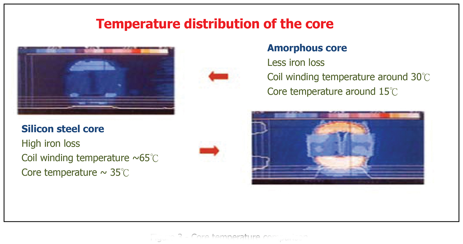
Figure 3. Core temperature comparison
Harmonic currents caused by source voltage distortions typically cause significant heating in ac motors, transformers, and any magnetic electrical device that employs ferrous metal in the flux path (See Figure 3). With increasing current frequency, stator windings, rotor circuits, and stator and rotor laminations tend to dissipate additional heat due primarily to eddy currents (exponential loss), hysteresis (linear loss), and, to a lesser degree, skin effect (linear loss). Leakage (e.g., stray) fields set up by harmonic currents in stator and rotor end windings also produce extra heat in any surrounding or nearby metal, according to Arrillaga, et al. [B3]) chapter 4.5.3.2.3.
Problem Definition
Data center operations differ from electronics operations. In data centers, enterprises add IT equipment to meet business demand, and the specifications of equipment installed by leased tenants may be unknown to operators. Therefore, huge financial losses or other damages could result if IT equipment is selected and installed without considering the use of passive/active harmonic filters to handle harmonic distortion. (See Figures 4 and 5.)
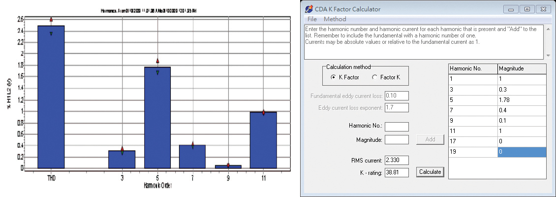
Figure 4. Commonly seen data center power system harmonics (voltage) (K Factor 38.81)
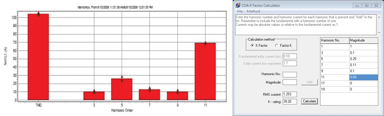
Figure 5. Commonly seen data center power system harmonics (Current) (K Factor 39.26)
Also when IT equipment is modified, added, or removed, the capacity of the filter must be adjusted to match the new system’s capacity and levels of harmonic distortion. The facility owner may object to this arrangement as well as to the extra costs. Electrical engineers must develop power quality strategies that can meet these objections.
Method: Isolation and Elimination (IE)
Focusing on the power system architecture and the harmonic problems discussed previously, our team used Matlab Simulink software to simulate power quality problems, test solutions, and identify an optimum solution to develop new products to test in an experiment.
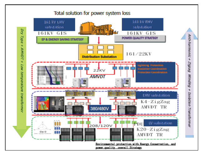
Figure 6. Overall power quality strategy for environmental protection and energy saving
First, we designed a power system architecture that isolated IT equipment from power equipment and that also used new low-temperature core products to help meet environmental protection, energy saving, and carbon reduction requirements as well as reduce required HVAC energy consumption. An amorphous dry-type low temperature K Type zigzag Dz0/2 winding transformer with isolation feature was the main component of this system. See Figures 6-12; Figures 11 and 12 show before and after performance characteristics.
In the past, project grounding concepts were not clearly defined, and engineers would not be familiar with actual site conditions, resulting in confusing grounding system connections. IEEE 1100 is rigorous when it comes to IT equipment grounding; therefore, achieving clean grounding across systems can be a major challenge. It is essential to establish an overall grounding system color code management to avoid wiring mismatches that lead to system downtime.
Outdoor wiring and conduit should bond to the building’s main grounding system to assure the concept of “all grounding and bonding terminated at single mass of earth point.” The overall grounding system comprises branches of each functional grounding system from the main grounding system. Connections between systems should not be improperly mixed in order to achieve isolated grounding functionality. Color coding differentiates between systems (See Figure 13).
The outdoor equipment enclosure grounding should be location specific, rather than being part of the common grounding system. For example, the chassis of the distribution panel on the rooftop should be bonded to adjacent outdoor equipment to ensure equipotential grounding and bonding (See Figure 14).
In addition, lightning risk should be evaluated in accordance with International Electrotechnical Commission (IEC) 62305-2 Protection standards, and the results should be used to build lightning protection equivalent to the grounding. Color coding the ground wire system can minimize problems in the future. Figure 15 is a recommended system.
Cost-benefit Analysis
At present, the power system architecture is only a single-layer. Starting in the second half of next year, there will be several newly constructed data center projects that adopt the IE method in dual-layer power system architectures, in which the IT equipment will use Amorphous K-20 grade with Dy and Dz zigzag winding transformers, and the power equipment will use K-4 grades with Dy and Dz zigzag winding transformers. We shall obtain test data during project commissioning to verify the cost benefit.
IE can be applied to different load characteristics by way of traditional power transformer windings to achieve power quality improvement. Not only we can increase the functionality of a transformer, which is already on the required equipment list, but we can also achieve harmonic reduction.
References
1. Design of Delta Primary – Transposed Zigzag Secondary (DTz) Transformer to Minimize Harmonic Currents on the Three-phase Electric Power Distribution System. Chairul Gagarin Irianto, Rudy
2. Three Phase Transformer Winding Configurations and Differential Relay Compensation. Lawhead, Larry; Hamilton, Randy; and Horak, John. Basler Electric Company.
3. IEEE Recommended Practice for Powering and Grounding Electronic Equipment (IEEE std 1100-2005)
4. A Probabilistic Analysis on the Harmonic Cancellation Characteristics of the Scott Transformer. Mazin, Hooman Erfanian and Gallant, Joey. Department of Electrical and Computer Engineering, University of Alberta, Edmonton, Canada.
5. Transformer Based Solutions to Power Quality Problems. de León, Francisco and Gladstone, Brian, Plitron Manufacturing Inc, and van der Veen, Menno, Ir. buro Vanderveen.
6. Power System Harmonic Effects on Distribution Transformers and New Design Considerations for K Factor Transformers. Jayasinghe, N.R; Lucas, J.R; and Perera Setiabudy, K.B.I.M; and Hudaya, Chairul.
7. Review and The Future of Amorphous Metal Transformers in Asia 2011 edition by Asia Energy Platform 2011
8. The Performance of Silicon and Amorphous Steel Core, Distribution Transformers at Ambient and Cryogenic Temperatures. Bodger, Pat; Harper, David; Gazzard, Matthew; O’Neill, Matthew, and Enright, Wade.
9. Wide Temperature Core Loss Characteristic of Transverse Magnetically Annealed Amorphous Tapes for High Frequency Aerospace Magnetic. Niedra, Janis N. and Schwarze, Gene E.
Figure 7. (Top, middle, bottom) Sub-systems architecture
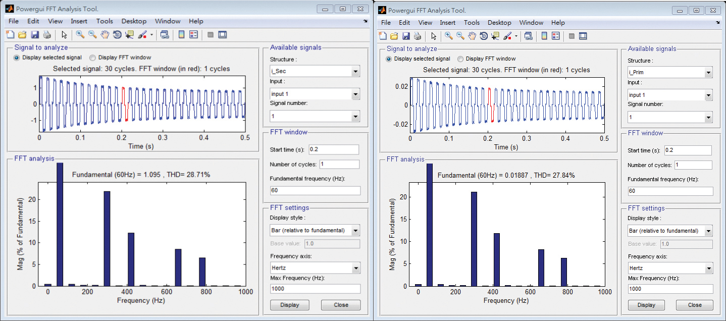
Figure 8. (Left) Secondary side of transformer. Figure 9. (Right) Primary side of transformer.
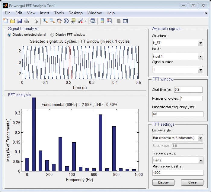
Figure 10. Total effect of the high-voltage side
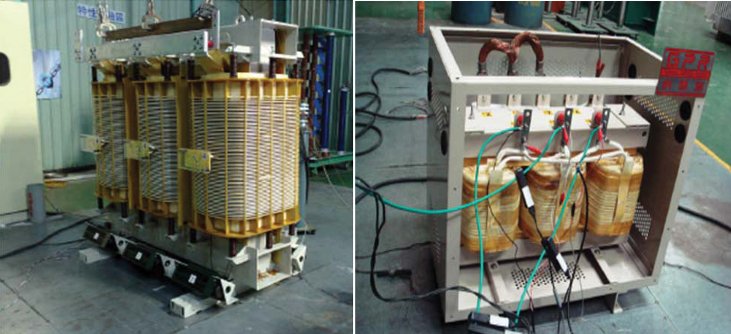
Figure 11. AMVDT_1000 kVA Dz0 Zigzag Dry Type HV Transformer/K-20 AMVDT 30 VA Dz0/2LVTransformer
Figure 12a. System before improvement
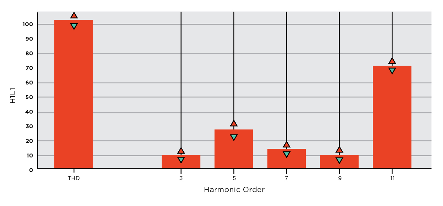
Figure 12b. System after improvement
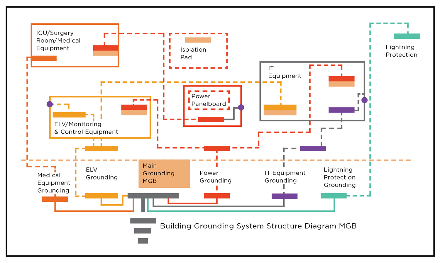
Figure 13. Building grounding
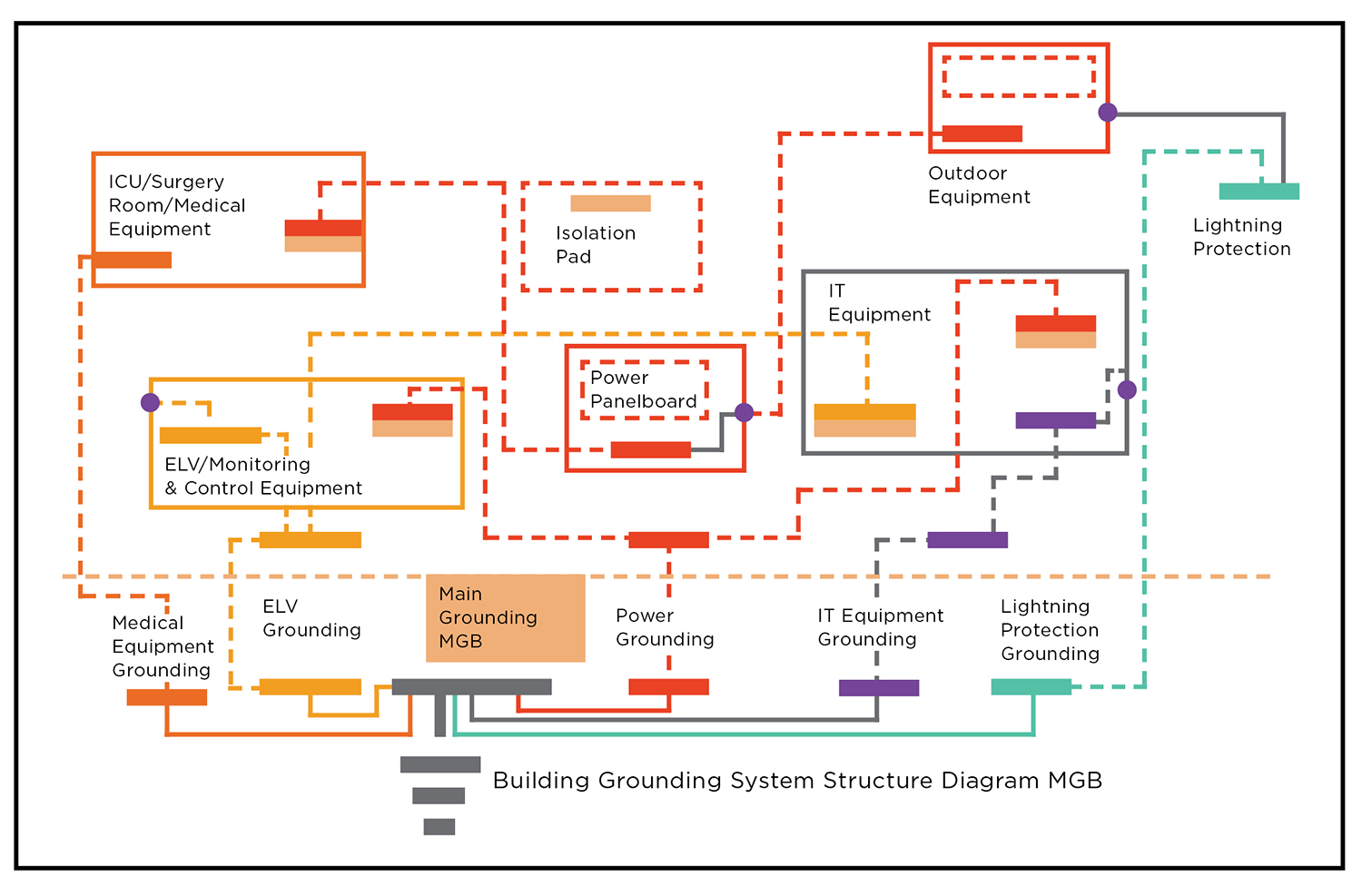
Figure 14. Outdoor grounding
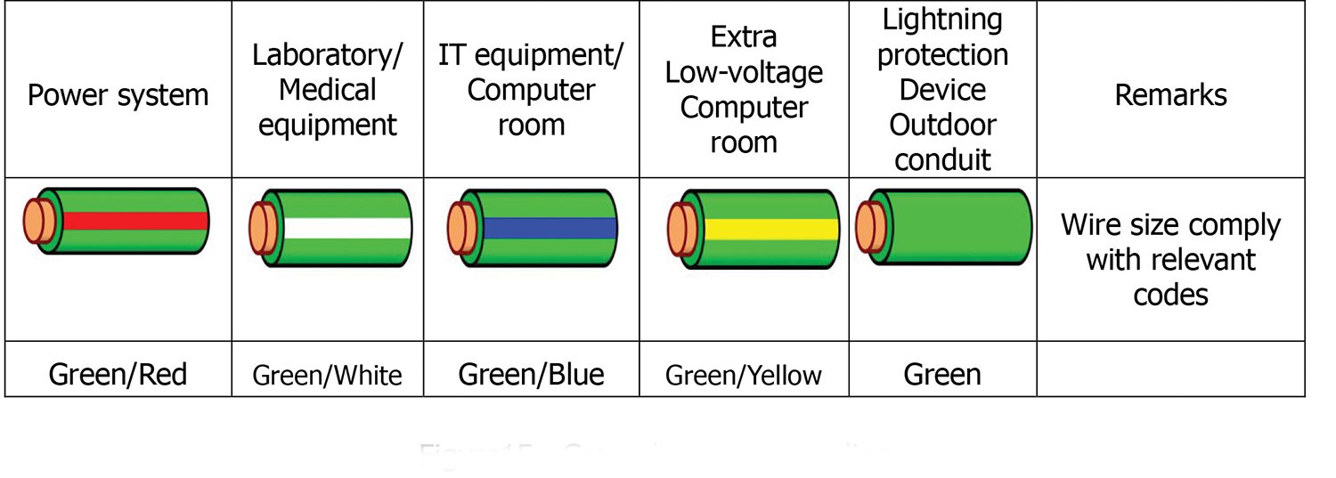
Figure 14. Outdoor grounding
Kuo-Chuan Chu is a licensed PE, who founded Sunrise Professional Engineering Company in 1994. He served as the president of Taiwan Professional Electrical Engineering Association from 2005 to 2007, obtained APEC and international engineer qualification in 2008, and served as chairman of the Taiwan International Project Management
 Association from 2009 to 2010.
Mr. Chu possesses a wide range of professional licenses and certifications including Uptime Institute Accredited Tier Designer (ATD). He was the first ATD data center designer in Asia.
Some representative projects include Taiwan Mobile’s Cloud IDC project (the first Uptime Institute Tier III Constructed Facility in North Asia, NCHC National Center for High-Performance Computing, China Medical University Hospital, Changhua Christian Hospital, and Yuan-lin branch LEED-NC/HC.


