
Saudi Aramco’s Cold Aisle Containment Saves Energy
Oil exploration and drilling require HPC
By Issa A. Riyani and Nacianceno L. Mendoza
Saudi Aramco’s Exploration and Petroleum Engineering Computer Center (ECC) is a three-story data center built in 1982. It is located in Dhahran, Kingdom of Saudi Arabia. It provides computing capability to the company’s geologists, geophysicists, and petroleum engineers to enable them to explore, develop, and manage Saudi Arabia’s oil and gas reserves. Transitioning the facility from mainframe to rack-mounted servers was just the first of several transitions that challenged the IT organization over the last three decades. More recently, Saudi Aramco reconfigured the legacy data center to a Cold Aisle/Hot Aisle configuration, increasing rack densities to 8 kilowatts per rack (kW/rack) from 3 kW/rack in 2003 and nearly doubling capacity. Further increasing efficiency, Saudi Aramco also sealed openings around and under the computer racks, cooling units, and the computer power distribution panel in addition to blanking unused rack space.
The use of computational fluid dynamics (CFD) simulation software to manage the hardware deployment process enabled Saudi Aramco to increase the total number of racks and rack density in each data hall. Saudi Aramco used the software to analyze various proposed configurations prior to deployment, eliminating the risk of trial and error.
In 2015 one of the ECC’s five data halls was modified to accommodate a Cold Aisle Containment System. This installation supports the biggest single deployment so far in the data center, 124 racks of high performance computers (HPC) with a total power demand of 994 kW. As a result, the data hall now hosts 219 racks on a 10,113-square-foot (940-square-meter) raised floor. To date, the data center hall has not experienced any temperature problems.
Business Drivers
Increasing demand by ECC customers requiring the deployment of IT hardware and software technology advances necessitated a major reconfiguration in the data center. Each new configuration increased the heat that needed to be dissipated from the ECC. At each step, several measures were employed to mitigate potential impact to the hardware, ensuring safety and reliability during each deployment and project implementation.
For instance, Saudi Aramco developed a hardware deployment master plan based on a projected life cycle and refresh rate of 3–5 years to transition to the Cold Aisle/Hot Aisle configuration. This plan allows for advance planning of space and power source allocation with no compromise to existing operation as well as fund allocation and material procurement (see Figures 1 and 2).

Figure 1. Data center configuration
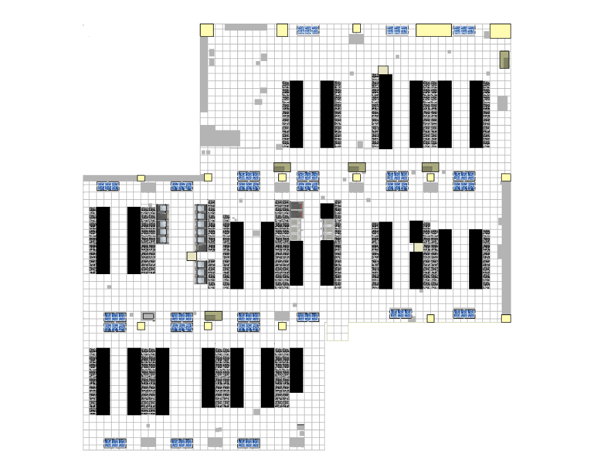
Current day
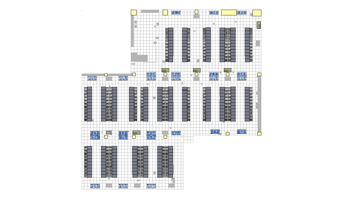
Masterplan
Figure 2. Data center plan view
Because of the age of the building and its construction methodology, the company’s engineering and consulting department was asked to evaluate the building structure based on the initial master plan. This department determined the maximum weight capacity of the building structure, which was used to establish the maximum rack weight to avoid compromising structural stability.
In addition, the engineering and consulting department evaluated the chilled water pipe network and determined the maximum number of cooling units to be deployed in each data hall, based on maximum allowable chilled water flow. Similarly, the department determined the total heat to be dissipated per Hot Aisle to optimize the heat rejection capability of the cooling units. The department also determined the amount heat to be dissipated per rack to ensure sufficient cooling as per manufacturer’s recommendation.
Subsequently, facility requirements based on these limiting factors were shared with the technology planning team and IT system support. The checklist includes maximum weight, rack dimensions, and the requirement for blanking panels and sealing technologies to prevent air mixing.
Other features of the data center include:
- A 1.5-foot (ft) [0.45 meter (m)] raised floor containing chilled water supply and return pipes for the CRAH units, cable trays for network connectivity, sweet water line for the humidifier, liquid-tight flexible conduits for power, and computer power system (CPS) junction boxes
- A 9-ft (2.8 m) ceiling height
- False ceilings
- Down-flow chilled water computer room air handling (CRAH) units
- CRAH units located at the end of each Hot Aisle
- Perforated floor tiles (56% open with manually controlled dampers)
- No overhead obstructions
- Total data center heat load of 1,200 kW
- Total IT load of 1,084 kW, which is constant for all three models
- Sealed cable penetrations (modeled at 20% leakage)
The 42U cabinets in the ECC have solid sides and tops, with 64% perforated front and rear doors on each cabinet. Each is 6.5-ft. high by 2-ft. wide by 3.61-ft. deep (2 m by 0.6 m by 1.10 m) and weighs 1874 pounds (850 kilograms). Rack density ranges from 6.0–8.0 kW. The total nominal cooling capacity is 1,582 kW from (25) 18-ton computer room air conditioning (CRAC) units.
Modeling Software
In 2007, Saudi Aramco commissioned the CFD modeling software company to prepare baseline models for all the data halls. The software is capable of performing transient analysis that suits the company’s requirement. The company uses the modeling software to simulate proposed hardware deployment, investigate deployment scenarios, and identify any stranded capacity.The modeling company developed several simulations based on different hardware iterations of the master plan to help establish the final hardware master plan with each Hot Aisle not exceeding a 125-kW heat load on a 16-rack Hot Aisle and not more than 8 kW per rack. After the modeling software company completed the initial iterations, Saudi Aramco acquired a perpetual license and support contract for the CFD simulation software in January 2010.
Saudi Aramco finds that the CFD simulation software makes it easier to identify and address heat stratification, recirculation, and even short-circuiting of cool air. By identifying the issues in this way, Saudi Aramco was able to take several precautionary measures and improve its capacity management procedures, including increasing cooling efficiency and optimizing load distribution.
Temperature and Humidity Monitoring System
With the CFD software simulation results at hand, the facilities management team looked for other means to gather data for use in future cooling optimization simulations while validating the results of CFD simulations. As a result, the facilities management group decided to install a temperature and humidity monitoring system. The initial deployment was carried out in 2008, with the monitoring of subfloor air supply temperature and hardware entering temperature.
At that time, three sensors were installed in each Cold Aisle for a total of six sensors. The sensors were positioned at the ends of each end of the row and in the middle, at the highest point of each rack. Saudi Aramco chose these points to get better understanding of the temperature variance (∆T) between the subfloor and the highest rack inlet temperature. Additionally, Saudi Aramco uses this data to monitor and ensure that all inlet temperatures are within the recommended ranges of ASHRAE and the manufacturer.
The real-time temperature and humidity monitoring system enabled the operation and facility management team to monitor and document unusual and sudden temperature variances allowing proactive responses and early resolution of potential cooling issues. The monitoring system gathers data that can be used to validate the CFD simulations and for further evaluation and iteration.
The Prototyping
The simulation models identified stratification, short circuiting, and recirculation issues in the data halls, which prompted the facilities management team to develop more optimization projects, including a containment system. In December 2008, a prototype was installed in one of the Cold Aisles (see Figure 3) using ordinary plastic sheets as refrigerated doors and Plexiglass sheets on aluminum frame, Saudi Aramco monitored the resulting inlet and core temperatures using the temperature and humidity monitoring system and internal system monitors prior to, during, and upon completion of installation to ensure no adverse effect with the hardware. The prototype was observed over the course of three months with no reported hardware issues.
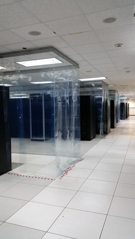
Figure 3 Prototype containment system
Following the successful installation of the prototype, various simulation studies were further conducted to ensure the proposed deployment’s benefit and savings. In parallel, Saudi Aramco looked for the most suitable materials to comply with all applicable standards, giving prime consideration to the safety of assets and personnel and minimizing risk to IT operations.

Table 1. Installation dates
When the Cold Aisle was contained, Saudi Aramco noticed considerable improvement in the overall environment. Containment improved cold air distribution by eliminating hot air mixing with the supply air from the subfloor, so that air temperature at the front of the servers was close to the subfloor supply temperature. With cooler air entering the hardware, the core temperature was vastly improved, resulting in lower exhaust and return air temperatures to the cooling units. As a result, the data hall was able to support more hardware
Material Selection and Cold Aisle Containment System installation
From 2009 to 2012, the facility management team evaluated and screened several products It secured and reviewed the material data sheets and submitted them to the Authority Having Jurisdiction (AHJ) for evaluation and concurrence. Each of the solutions would require some modifications to the facility before being implemented. The facility management team evaluated and weighed the impact of these modifications as part of the procurement process.
Of all the products, one stood out from the rest; the use of easy to install and transparent material addresses not only safety but also eliminated the need for modifications of the existing infrastructure, which translates to considerable savings in terms of project execution and money.
Movement in and out of the aisle is easy and safe as people can see through the doors and walls. Additionally, the data hall lighting did not need to be modified since it was not obstructed. Even the fire suppression system was not affected since it has a fusible link and lanyard connector. The only requirement by AHJ prior to deployment was additional smoke detectors in the Cold Aisle itself.
To comply with this requirement, an engineering work order was raised for the preparation of the necessary design package for the modification of the smoke detection system. After completing the required design package including certification from a chartered fire protection engineer as mandated by the National Fire Protection Association (NFPA), it was established that four smoke detectors were to be relocated and an additional seven smoke detectors installed in the data hall.
Implementation and challenges
Optimizations and improvements always come with challenges; the reconfiguration process necessitated close coordination between the technology planning team, IT system support, ECC customers, the network management group, Operations, and facility management. These teams had to identify hardware that could be decommissioned without impacting operations, prepare temporary spaces for interim operations, and then take the decommissioned hardware out of the data hall, allowing the immediate deployment of new hardware in Cold Aisle/Hot Aisle. Succeeding deployments follow the master plan, allowing the complete realignment process to be completed in five years.
Installation of the Cold Aisle Containment System did not come without challenges; all optimization activities, including relocating luminaires in the way of the required smoke detectors had to be completed with no impact to system operations. To meet this requirement, ECC followed a strict no work permit–no work procedure; work permits are countersigned by operation management staff on duty during issuance and prior to close out. This enabled close monitoring of all activities within the data halls, ensuring safety and no impact to daily operation and hardware reliability. Additionally, a strict change management documentation process was utilized and adhered to by the facility management team and monitored by operation management staff; all activities within the data halls have to undergo a change request approval process.
Operations management and facility management worked hand in hand to overcome these challenges. Operations management, working in three shifts, closely monitored the implementation process, especially after regular working hours. Continuous coordination between contractors, vendors, operation staff, and facility management team enabled smooth transition and project implementations eliminating any showstoppers along the way.
Summary
The simulation comparison in Figure 4 clearly shows the benefits of the Cold Aisle Containment System. Figure 4a shows hot air recirculating around the end of the rows and mixing with the cold air supply to the Cold Aisles. In Figure 4b, mixing of hot and cold air is considerably reduced with the installation of the 14 Cold Aisle containment systems. The Cold Aisles are better defined and clearly visible in the figures, with less hot air recirculation, but the three rows without containment still suffer from recirculation. In Figure 4c, the Cold Aisles are far better defined, and hot air recirculation and short circuiting are reduced. Additionally, the exhaust air temperature from the hardware has dropped considerably.
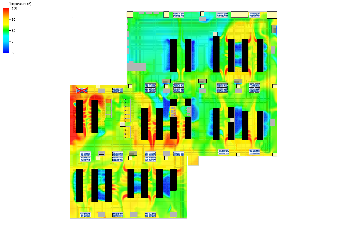
Figure 4a. Without Cold Aisle Containment
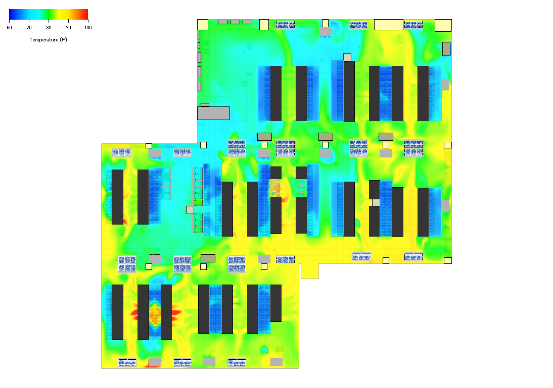
Figure 4b. With current Cold Aisle Containment (14 of 17 aisles)
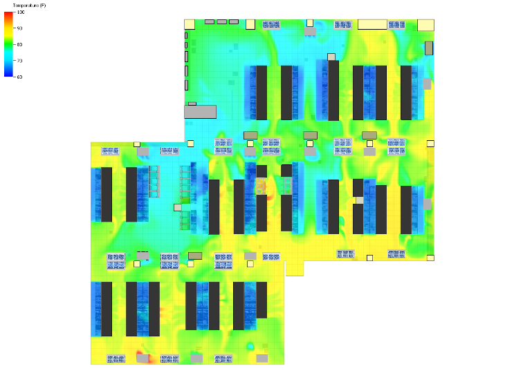
Figure 4c. With full Cold Aisle Containment
Figures 5–11 show that the actual power and temperature readings taken from the sensors installed in the racks validated the simulation results. As shown in Figures 4a and 5a, the power draw of the racks in Aisles 1 and 2 fluctuates while the corresponding entering and leaving temperature was maintained. On Week 40, the temperature even dropped slightly despite the slight increase in the power draw. The same can also be observed in Figures 6 and 7. All these aisles are fitted with a Cold Aisle Containment System.
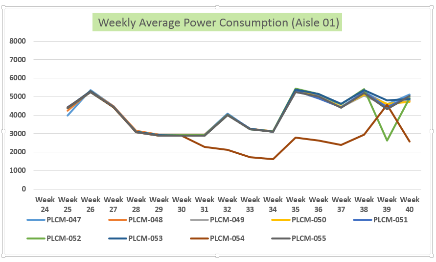
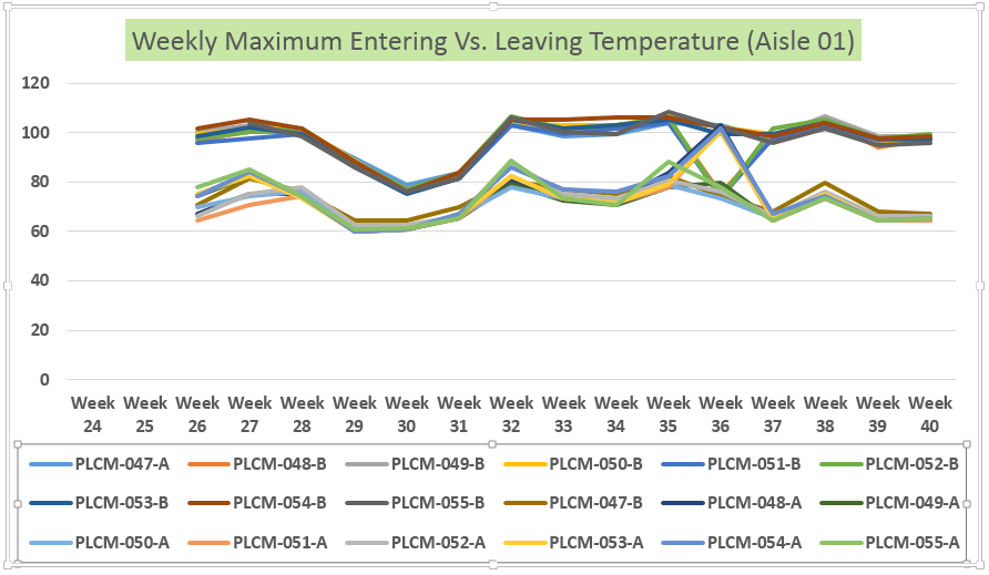
Figure 5. Actual Power utilization, entering temperature, and leaving temperature
Aisle 01 (installed on July 30, 2015 – week 31)
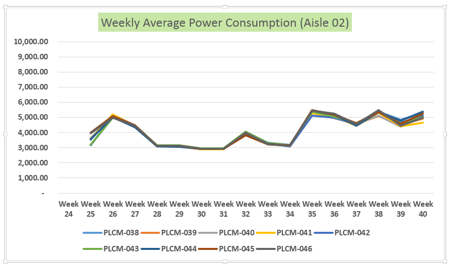
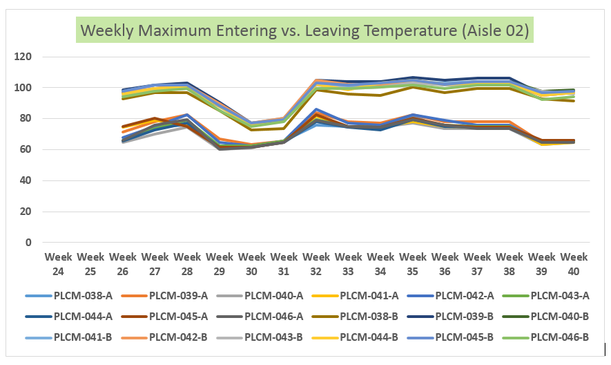
Figure 6. Aisle 2 (installed on July 28, 2015 – week 31)
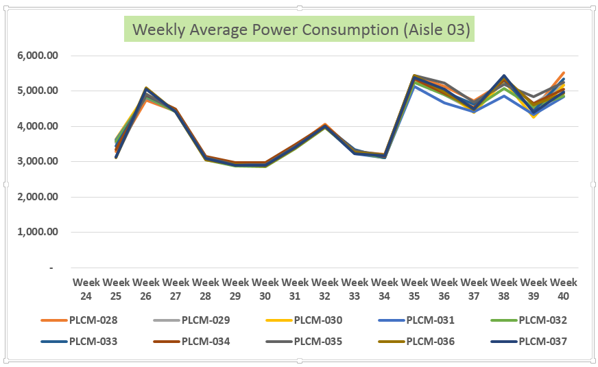
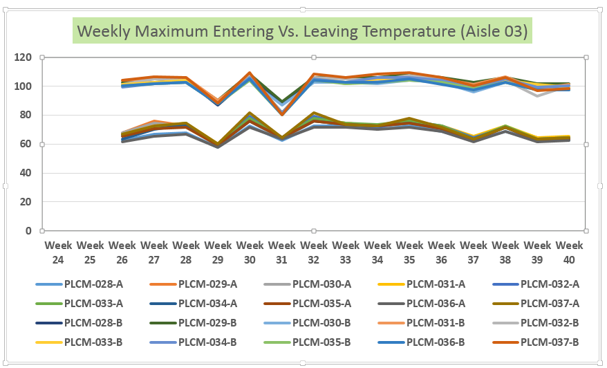
Figure 7. Aisle 3 (installed on March 7, 2015 – week 10)
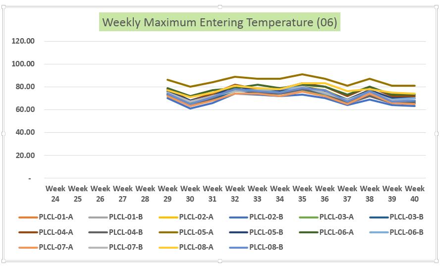
Figure 8. Aisle 6 (installed on April 09, 2015 – week 15)
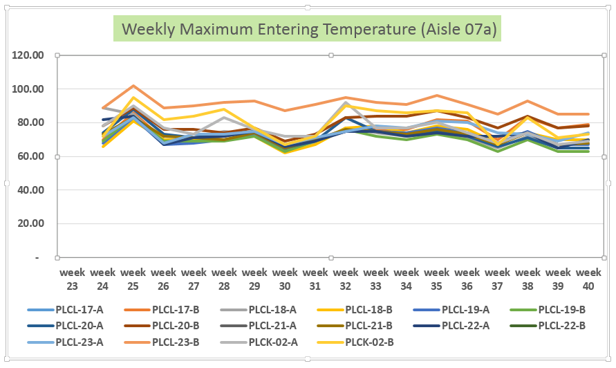
Figure 9. Aisle 7a (a and b) and Aisle 7b (c and d)
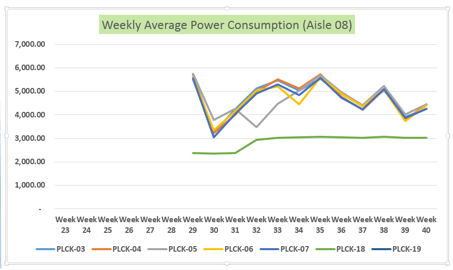
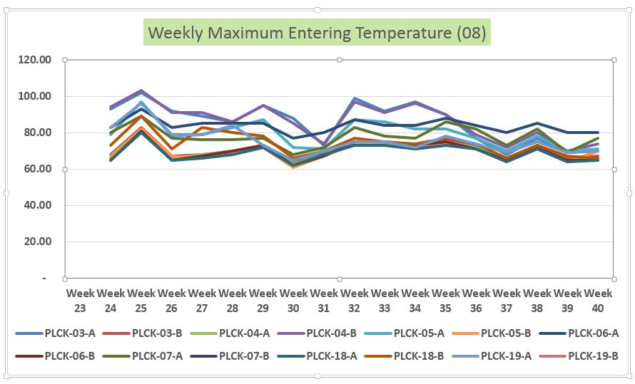
Figure 10. Aisle 8 (installed on February 28, 2015 – week 09)
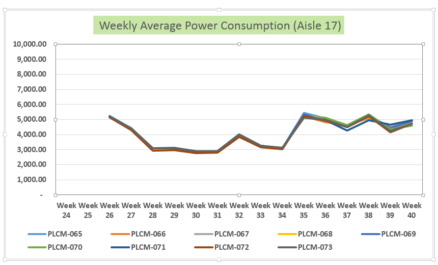
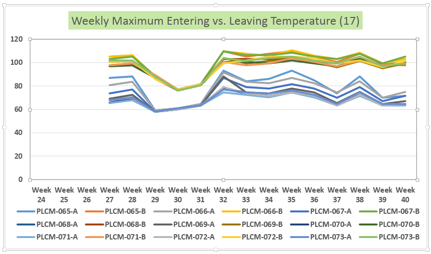
Figure 11. Aisle 17 (no Cold Aisle installed)
Additionally, Figure 11 clearly shows slightly higher entering and leaving temperature as well as fluctuation in the temperature readings that coincided with the power draw fluctuation of the racks within the aisle. This aisle has no containment.
The installation of the Cold Aisle Containment System greatly improved the overall cooling environment of the data hall (see Figure 12). Eliminating hot and cold air mixing and short circuiting allowed for more efficient cooling unit performance and cooler supply and leaving air. Return air temperature readings in the CRAH units were also monitored and sampled in Figure 12, which shows the actual return air temperature variance as a result of the improved overall data hall room temperature.
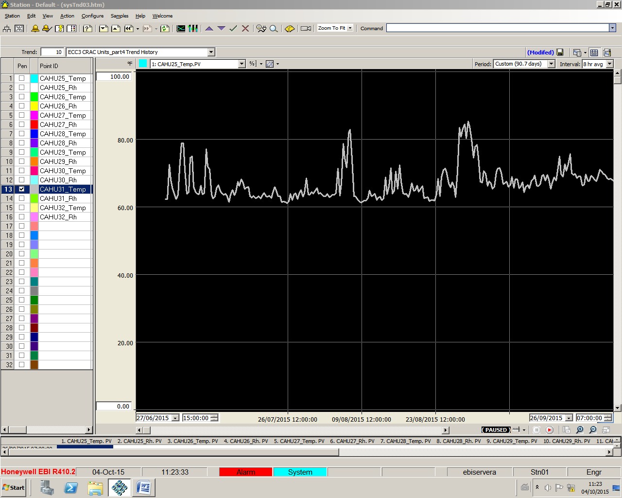
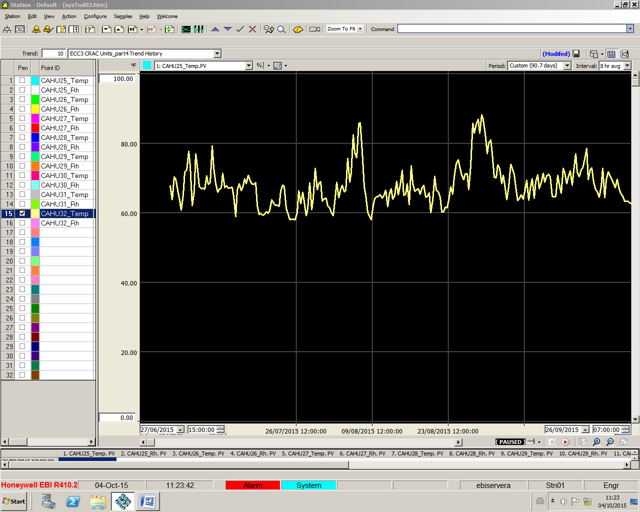

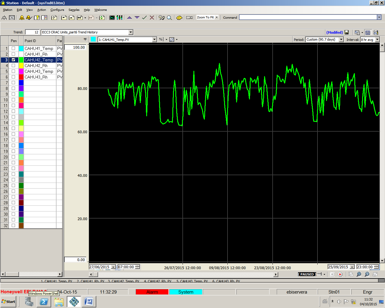
Figure 11. Computer air handling unit actual return air temperature graphs
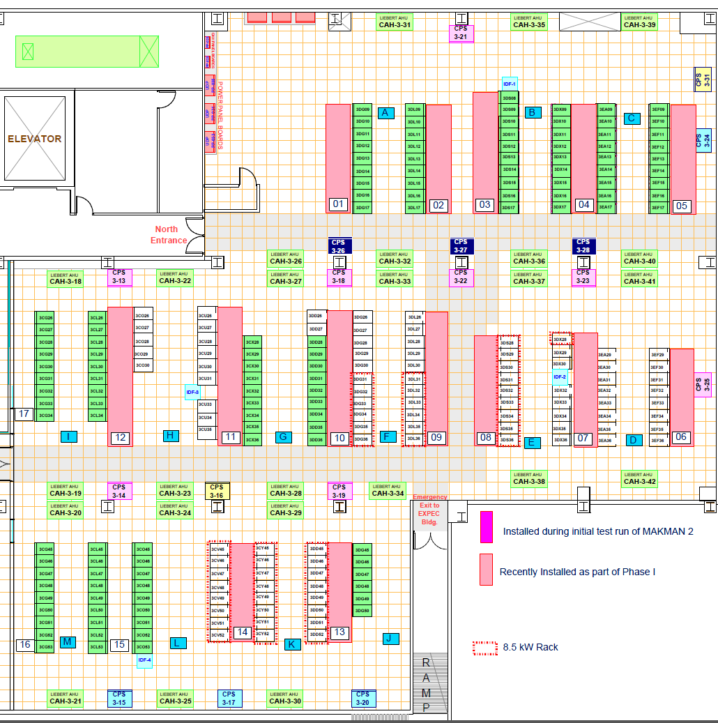
Figure 13. Cold Aisle floor layout
The installation of the Cold Aisle Containment System allows the same data hall to host the company’s MAKMAN and MAKMAN-2 supercomputers (see Figures 5
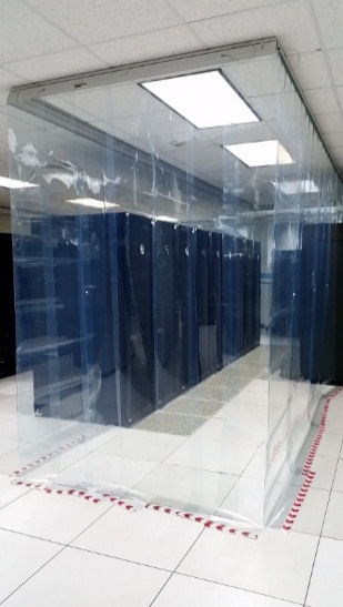
Figure 14. Installed Cold Aisle Containment System
). Both MAKMAN and MAKMAN-2 appear on the June 2015 Top500 Supercomputers list.

Issa Riyani
Issa A. Riyani joined the Saudi Aramco Exploration Computer Center (ECC) in January 1993. He graduated from King Fahad University of Petroleum and Minerals (KFUPM) in Dhahran, Kingdom of Saudi Arabia, with a bachelor’s degree in electrical engineering. Mr. Riyani currently leads the ECC Facility Planning & Management Group and has more than 23 years experience managing ECC facilities.

Nacianceno L. Mendoza
Nacianceno L. Mendoza joined the Saudi Aramco Exploration Computer Center (ECC) in March 2002. He holds a bachelor of science in civil engineering and has more than 25 years of diverse experience in project design, review, construction management, supervision, coordination and implementation. Mr. Mendoza spearheaded the design and implementation of the temperature and humidity monitoring system and deployment of Cold Aisle Containment System in the ECC.