Close Coupled Cooling and Reliability
Achieving Concurrently Maintainable and Fault Tolerant cooling using various close coupled cooling technologies
By Matt Mescall
Early mainframe computers were cooled by water at the chip level. Then, as computing moved to the distributed server model, air replaced water. Typically, data centers included perimeter computer room air condition (CRAC) units to supply cold air to a raised floor plenum and perforated floor tiles to deliver it to IT equipment. These CRAC units were either direct-expansion (DX) or chilled-water units (for simplicity, CRAC will be used to refer to either kind of unit). This arrangement worked for the past few decades while data centers were primarily occupied by low-density IT equipment (< 2-4 kilowatts [kW] per rack). However, as high-density racks become more common, CRAC units and a raised floor may not provide adequate cooling.
To address these situations, data center cooling vendors developed close coupled cooling (CCC). CCC technology includes in-row, in-rack, above–rack, and rear-door heat exchanger (RDHx) systems. Manufacturers typically recommend the use of a Cold Aisle/Hot Aisle arrangement for greater efficiency, which is a best practice for all data center operations. As rack density increased due to IT consolidation and virtualization, CCC moved from being a solution to an unusual cooling situation to being the preferred cooling method. Implemented properly, a CCC solution can meet the Concurrently Maintainable and Fault Tolerant requirements of a data center.
While an air handler may provide humidity control, the close coupled cooling solution provides the onlycooling for the IT equipment in a data center. Additionally, it is assumed that the reader understands how to design a direct-expansion or chilled-water CRAC based cooling system to meet Concurrent Maintainability and Fault Tolerant requirements. This paper does not address Concurrent Maintainability and Fault Tolerant requirements for a central cooling plant, only the CCC system in the data hall.
Meeting Concurrently Maintainable and Fault Tolerant Requirements
First, let’s clarify what is required for a Concurrently Maintainable (Tier III) and a Fault Tolerant (Tier IV) cooling system. This discussion is not a comprehensive description of all Concurrently Maintainable and Fault Tolerant requirements, but it provides the basis for the rest of the discussion in this paper.
A Concurrently Maintainable system must have redundant capacity components and independent distribution paths, which means that each and every capacity component and distribution path element can be taken out of service for maintenance, repair, or replacement without impacting the critical environment.
To meet this requirement, the system must have dry pipes (no flowing or pressurized liquid) to prevent liquid spills when maintaining pipes, joints, and valves. Draining a pipe while it is disassembled is allowed, but hot tapping and pipe freezing are not. A Fault Tolerant cooling system may look like a Concurrently Maintainable system, but it must also autonomously respond to failures, including Continuous Cooling, and compartmentalize the chilled-water and/or refrigerant pipes outside the room of use (typically the computer room).
There are several different types and configurations of CCC. For simplicity, this paper will break them into two groups, in-row and above–row, and RDHx. While there are other CCC solutions available, the same concepts can be used to provide a Concurrently Maintainable or Fault Tolerant design.
In-row and above-row CCC
When data center owners have a business requirement for a high density data center to be Concurrently Maintainable or Fault Tolerant, a CCC design poses special circumstances that do not exist with room-based cooling. First, airflow must be considered. A CRAC-unit-based cooling design that is Concurrently Maintainable or Fault Tolerant has N+R cooling units that provide cooling to the whole room. When a redundant unit is off for maintenance or suffers a fault, the IT equipment still receives cooling from the remaining CRAC units via the perforated tiles in the Cold Aisle. The cooling in any Cold Aisle is not affected when the redundant unit is offline. This arrangement allows for one or two redundant CRAC units in an entire room (see Figure 1).
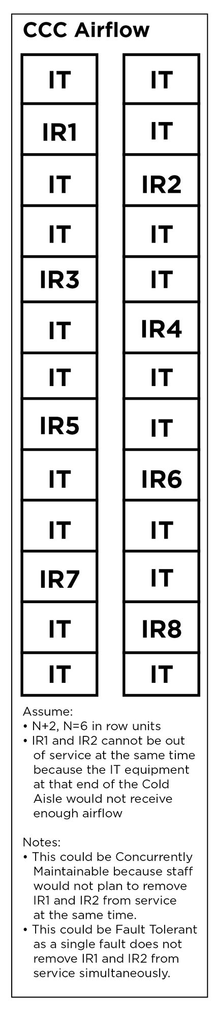
Figure 1. CCC airflow considerations
CCC provides cooling to the specific Cold Aisle where the unit is located. In other words, CCC units cannot provide cooling to different Cold Aisles the way CRAC units can. Accordingly, the redundant CCC unit must be located in the aisle where the cooling is required. In addition to having sufficient redundant cooling in every Cold Aisle, distance from the cooling unit to the IT equipment must also be considered. In-row and above row cooling units typically can provide cold air for only a limited distance. The design must take into account the worst-case scenario during maintenance or a failure event.
After considering the number of units and their location in the Cold Aisle, design team must consider the method of cooling, which may be air-cooled direct expansion (DX), chilled water, or a pumped refrigerant. Air-cooled DX units aretypically matched with their own condenser units. Other than proper routing, piping for air-cooled DX units require no special considerations.
Piping to chilled-water units is either traditional chilled-water piping or a cooling distribution unit (CDU). In the former method chilled water is piped directly to CCC units, similar to CRAC units. In this case, chilled-water piping systems are designed to be Concurrently Maintainable or Fault Tolerant in the same way as single-coil, room-based CRAC units.
The latter method, which uses CDUs, poses a number of special considerations. Again, chilled-water piping to a CDU and to single-coil, room-based CRAC units is designed to be Concurrently Maintainable or Fault Tolerant in the same way. However, designers must consider the impact to each Cold Aisle when a CDU is removed from service or suffers a fault.
If any single CDU provides cooling to more than the redundant number of cooling units in any aisle, the design is not Concurrently Maintainable or Fault Tolerant. When CDUs are located outside of the server room or data hall in a Fault Tolerant design, they must be properly compartmentalized so that a single event does not remove more than the redundant number of cooling units from service. A Fault Tolerant system also requires Continuous Cooling, the ability to detect, isolate, and contain a fault, and sustain operations. In a CCC system that rejects heat to a chilled-water system, the mechanical part of Continuous Cooling can be met with an appropriate thermal storage tank system that is part of a central plant.
A CCC system that rejects heat to outside air via refrigerant and a condenser will likely rely on uninterrupted power to provide Continuous Cooling which will be discussed in the following paragraphs.
Some CCC systems use pumped refrigerant. These systems transfer heat from pumped refrigerant to a building’s chilled-water system, a glycol system, or an external condenser unit.
Due to the similarities between chilled-water and glycol systems with respect to the piping headers, glycol and chilled water systems will be treated the same for purposes of this paper.. The heat transfer occurs at an in-room chiller or heat exchanger that, for the purposes of this discussion, is similar to a CDU. The Con- currently Maintainable and Fault Tolerant design considerations for a pumped refrigerant system are the same as a chilled-water system that uses a CDU.
The system that powers all CCC components must be designed to ensure that the electrical system does not defeat the Concurrent Maintainability or Fault Tolerance of the mechanical system. In a Concurrently Maintainable mechanical system electrical design, no more than the redundant number of cooling units may be removed from service when any part of the electrical system is removed from service in a planned manner. This requirement includes the cooling within any aisle, not just the room as a whole. Designing the CCC units and the associated CDUs, in-room chillers, or heat exchangers in a 2N configuration greatly simplifies the electrical distribution.
Providing an A feed to half of the units and a B feed to the other half of the units while paying attention to the distribution of the CCC units, will typically provide a Concurrently Maintainable electrical design.
If the cooling system is in an N+R configuration, the distribution of the power sources will require special coordination. Typically, the units will be dual fed, which can be accomplished by utilizing an internal transfer switch n the units, an external manual transfer switch, or an external automatic transfer switch. This requirement applies to all components of the CCC system that require power to cool the critical space, including the in-row and above-row units, the in-room chillers, heat exchangers, and any power that is required for CDUs (see Figure 2).
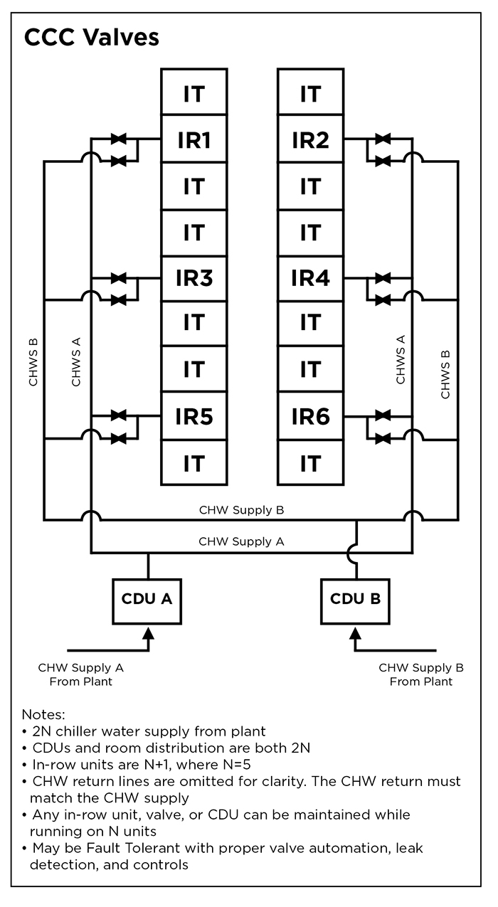
Figure 2. CCC valve scenario
When any part of a Fault Tolerant electrical design for a mechanical system experiences a fault no more than the redundant number of cooling units may be removed from service. The same Concurrently Maintainable concepts apply to a Fault Tolerant electrical system; however, all of the transfer switches must be automatic and cannot rely on human intervention to respond to a fault. Additionally, in order to provide Continuous Cooling, uninterruptible power must be provided for cooling fans, in-room chillers and heat exchangers, pumps, and CDUs. A CCC system that uses DX and condensers to reject heat to outside air will require uninterrupted power to all system components to achieve Continuous Cooling.
The controls for these systems must also be considered in the design and meet the appropriate Concurrent Maintainability and Fault Tolerant requirements.
RDHx
The requirements for a Concurrently Maintainable or Fault Tolerant RDHx cooling solution are similar to those for in-row cooling. The RDHx units typically use chilled water or a pumped refrigerant and CDUs, in-room chillers, or heat exchangers. These units need to meet all of the Concurrent Maintainability
or Fault Tolerant requirements of in-row CCC units. Airflow when a door is removed from service for either a planned event or due to a failure is a major consideration. When an RDHx solution cools an entire data center, it may be configured in a front-to-back rack configuration. When one or more doors are removed from service, the affected racks will blow hot exhaust air into the racks behind them, which may cause them to overheat, depending on the heat load.
This configuration does not meet Concurrent Maintainability or Fault Tolerant requirements, which require that the cooling system provide N cooling to all critical equipment during a planned maintenance event or a failure. Placing the racks in a Cold Aisle/Hot Aisle configuration may not meet this requirement as exhaust air from the affected rack may circulate over its top from the Hot Aisle and overheat the servers at the top of the rack and possibly adjacent racks. The same airflow issue is possible for racks placed at the end of rows when their RDHx is not working.
Summary
Using CCC as the only form of cooling in the data center is becoming more common. CCC provides additional challenges to meet Concurrent Maintainability and Fault Tolerant requirements beyond those typically experienced with a CRAC-based cooling system. The challenges of different airflow, when compared to room- based CRACs, and ensuring that the consequential impact of maintenance and failures on the additional capacity components and distribution systems do not remove more than the redundant number of units from service can be met with careful consideration when designing all parts of the CCC system.

Matt Mescall
Matthew Mescall, PE, is a senior consultant for Uptime Institute Professional Services and Tier Certification Authority, where he performs audits and provides strategic- level consulting and Tier Certification reviews. Mr. Mescall’s career in critical facilities spans 12 years and includes responsibilities in planning, engineering, design, construction, and operation. Before joining Uptime Institute, Mr. Mescall was with IBM, where he operated its Boulder, CO, data center and led a worldwide team analyzing best practices across IBM data centers to ensure consistent, cost-effective reliability.Mr. Mescall holds a BS degree in Civil Engineering from the University of Southern California, a MS in Civil Engineering from the Georgia Institute of Technology, and a Masters Certificate in Project Management from George Washington University.