U.S. Bank Upgrades Its Data Center Electrical Distribution
Open heart surgery on the data center: Switchgear replacement in a live facility
By Mark Johns
U.S. Bank emerged during the 1990s from mergers and acquisitions among several major regional banks in the West and Midwest. Since then, the company continued to grow through additional large acquisitions and mergers with more than 50 banks. Today, U.S. Bancorp is a diversified American financial services holding company headquartered in Minneapolis, MN. It is the parent company of U.S. Bank National Association, which is the fifth largest bank in the United States by assets, and fourth largest by total branches. U.S. Bank’s branch network serves 25 midwestern and western states with 3,081 banking offices and 4,906 ATMs. U.S. Bancorp offers regional consumer and business banking and wealth management services, national wholesale and trust services and global payments services to over 15.8 million customers.
Rich in history, US Bancorp operates under the second oldest continuous national charter—originally Charter #24—granted during Abraham Lincoln’s administration in 1863. In addition, U.S. Bank helped finance Charles Lindbergh’s historic flight across the Atlantic. For sheer volume, U.S. Bank is the fifth-largest check processor in the nation, handling 4 billion paper checks annually at 12 processing sites. The bank’s air and ground courier fleet moves 15 million checks each day.
Energy Park Site
U.S. Bank relies on its Energy Park site in St. Paul, MN, to support these operations. Energy Park comprises a 350,000-square-foot (ft2) multi-use building that houses the check production operations and 40,000-ft2 data center, as well as support staff for both. Xcel Energy provides two 2,500-kilovolt-ampere (kVA) feeds to the data center and two 2,000-kVA feeds to the rest of the building.
The utility’s data center feeds supply power to two automatic throw over switches (ATO); each ATO feeds two transformers. Two transformers support the data center, and two other transformers support check production and power for the rest of the building, including offices and HVAC (see Figures 1-3).
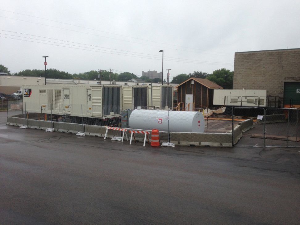
Figure 1. Temporary stand-alone power plant
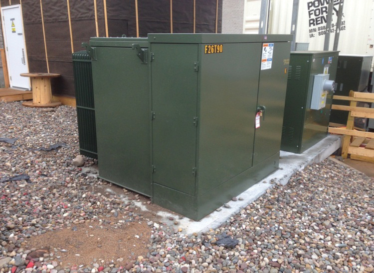
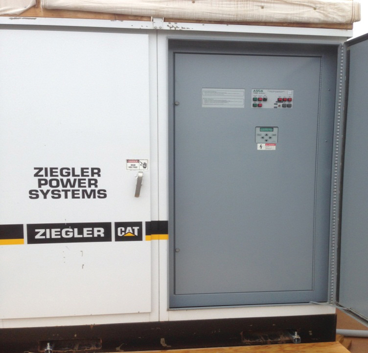
Figures 2 and 3. Utility transfer and ATS
A single UPS module feeds the check production area. However, two separate multi-module, parallel redundant UPS systems feed data center loads. Four N+1 1,500-kilowatt (kW) standby-rated engine generators backup the three UPS systems through existing switchgear distribution. The data center switchgear is a paralleling/closed-transition type, and the check production area switchgear is an open-transition type. The remaining office area space is not backed up by engine generators.
Project Summary
To ensure data center reliability, U.S. Bank initiated an Electric Modernization Project (data center electrical distribution). The project included replacing outdated switchgear and UPS systems, which were no longer supported by the manufacturer. In the project’s first phase, Russelectric paralleling switchboards were selected to replace existing equipment and create two separate distribution systems, each backed up by existing engine generators. Mechanical and UPS loads are divided between the two systems, so that either one can support the data center. Switchgear tie breakers increase overall redundancy. The facility benefits from new generator controls and new switchgear SCADA functionality, which will monitor and control utility or generator power.
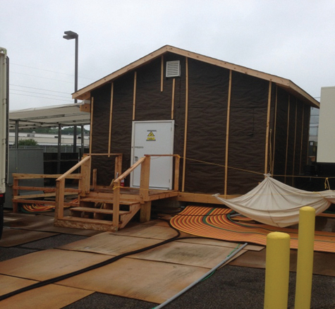
Since this project was undertaken in a live facility, several special considerations had to be addressed. In order to safely replace the existing switchgear, a temporary stand-alone power plant, sized to support all of the data center loads, was assembled in a parking lot just outside the building’s existing electric/switchgear room (see Figures 4-6). The temporary power plant consisted of a new utility transformer, powered from one of the utility’s ATOs, which supplies power to an automatic transfer switch (ATS). The ATS supplies power from either the utility feeds or the standby-rated engine generators to a new distribution switchboard to support data center loads. The switchboard was installed inside a small building to protect it from the elements. Maintenance bypass switches enable staff to work on the ATS.
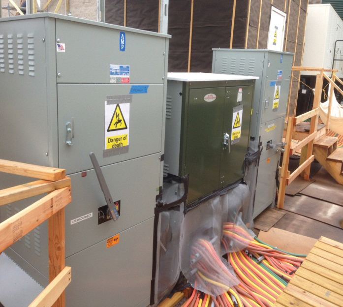
Figure 4. Maintenance bypass switches were installed to allow for work on the ATS
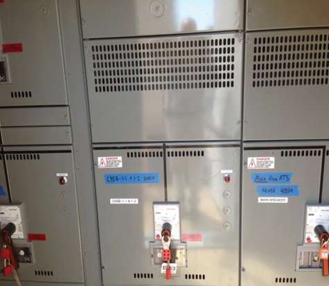
Figure 5 (Top) and 6 (Bottom). Switchboard was installed in a small building
Each standby-rated engine generator has two sources of fuel oil. The primary source is from a bulk tank, with additional piping connected to the site’s two existing 10,000-gallon fuel oil storage tanks to allow for filling the bulk tank or direct feed to the engine generators (see Figure 7).
Transferring Data Center Loads
U.S. Bank’s commissioning of the stand-alone power plant including testing the ATS, load testing the engine generators, infrared (IR) scanning all connections, and a simulated utility outage. Some additional cabling was added during commissioning to address cable heating due to excessive voltage drop. After commissioning was completed, data center loads were transferred to the stand-alone plant. This required providing temporary circuits for select mechanical equipment and moving loads away from four panelboards (two for mechanical equipment and two for the UPS), so that they could be shut down and re-fed from the temporary power plant. The panelboards were transferred one at a time to keep the data center on-line throughout all this work. The transfer work took place over two weekends.
The mechanical loads were sequenced first in order to put load on the stand-alone plant to provide a stable power source when the UPS systems were cut over and brought on-line. Data center loads were transferred to engine-generator power at the beginning of each day to isolate the data center from the work.
On the first Saturday devoted to the transfer process, the mechanical loads were rotated away from the first panelboard to be re-fed. Equipment requiring temporary power was cut over (see Figure 8). The isolated panelboard was then shut down and re-fed from the stand-alone plant. Once the panelboard was re-fed and power restored to it, equipment receiving temporary power was returned to its normal source. Mechanical loads were rotated back to this panelboard, so that the second panelboard could be shut down and re-fed. Data center loads were transferred back to utility power at the end of each day.
The Sunday mechanical cut over followed the same sequence as Saturday, except the stand-alone power plant, with live load, was tested at the end of the day. This testing included having Xcel Energy simulate a utility outage to the data center, which the utility did with data center loads still on engine-generator power so as not to impact the data center.
UPS were transferred the following weekend. On Saturday, the two UPS systems were transferred to engine-generator power and put into maintenance bypass so their primary power sources could be re-fed from the stand-alone power plant. At the end of the day, the two UPS systems went back on-line and transferred back to utility power. On Sunday, workers cut over the UPS maintenance bypass source. That day’s work concluded with additional testing of the stand-alone power plant, including another simulated utility outage to see how the plant would respond while supporting entire data center.
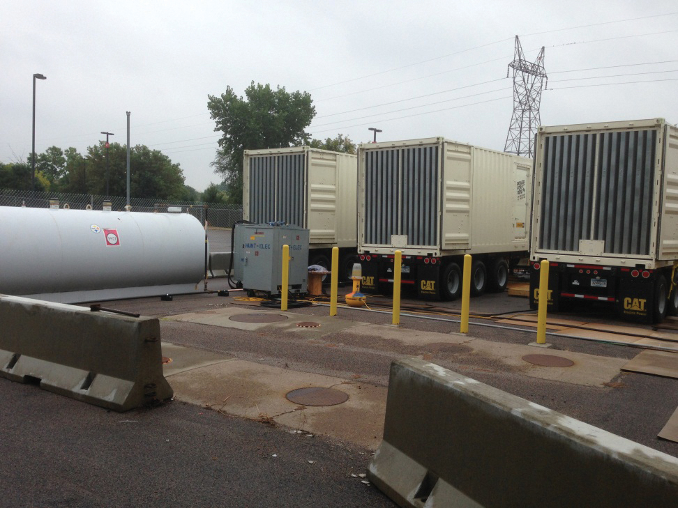
Figure 7. Standby-rated engine generators have two sources of fuel oil
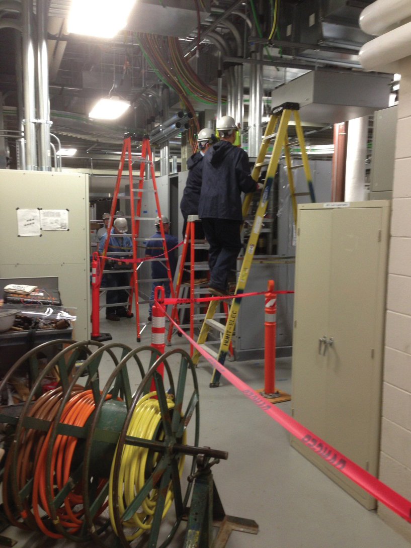
Figure 8. Data center loads were transferred to the temporary stand-alone power plant over the course of two weekends
Cable Bus Installation
At the same time the stand-alone power plant was assembled and loads cut over to it, four sets of cable trays and cables were installed to facilitate dividing the UPS loads. These four sets of cable trays had to be run through office and production areas to get to the existing UPS room, which is a run of approximately 625 feet (see Figure 9). Each tray served one of the four primary and maintenance bypass UPS systems.
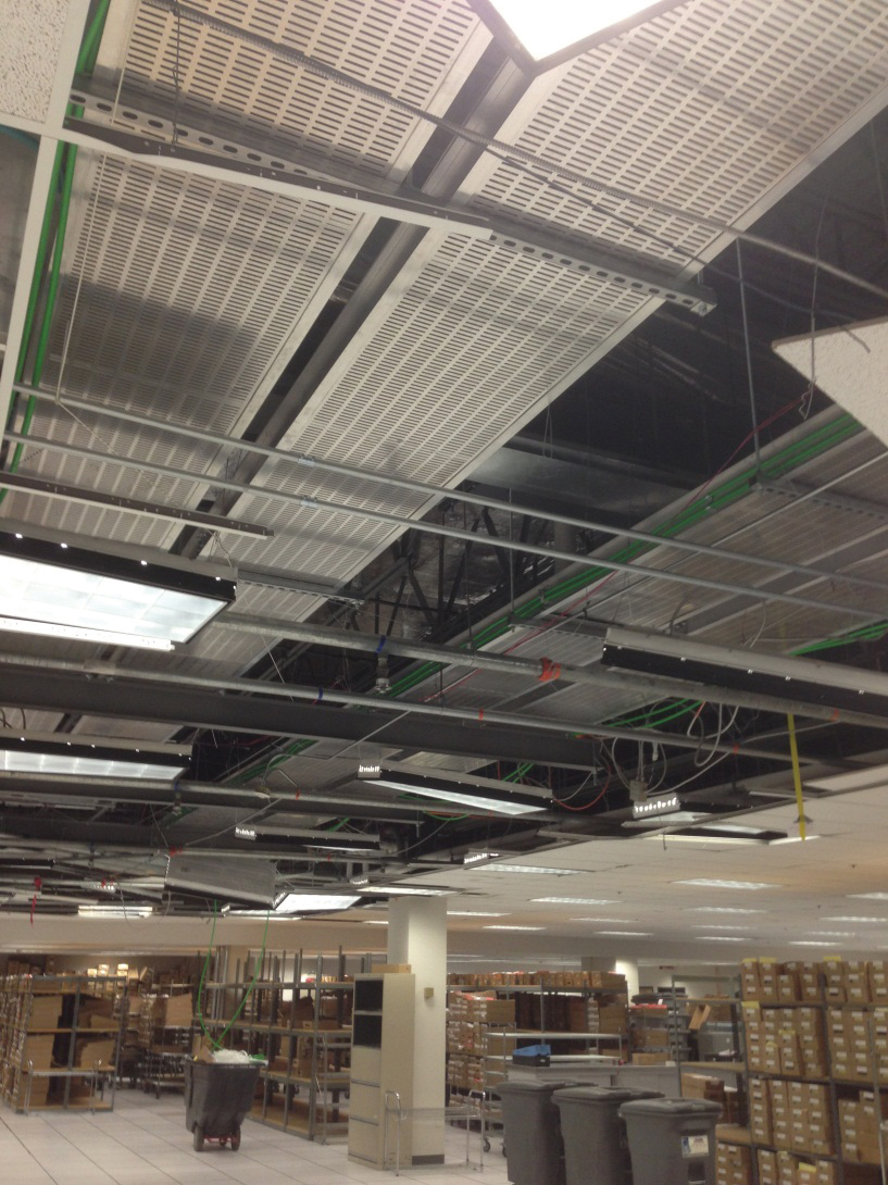
Figure 9. New cable buss ran about 625 feet through the facility
Switchgear and Generators
After the data center loads were transferred over to the stand-alone power plant, the old switchgear was disconnected from utility power so it could be disassembled and removed from the facility (see Figures 10 and 11). Then, the new switchgear was installed (see Figures 12 and 13).
The switchgear was designed for even distribution of loads, with an A (yellow) side and a B (blue) side (see Figure 14). Each side supports one of the two UPS systems, one of the two chillers with its pumps and towers, and half of the computer room cooling units.
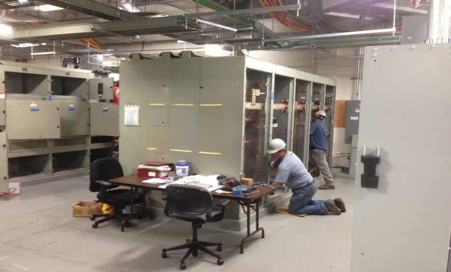
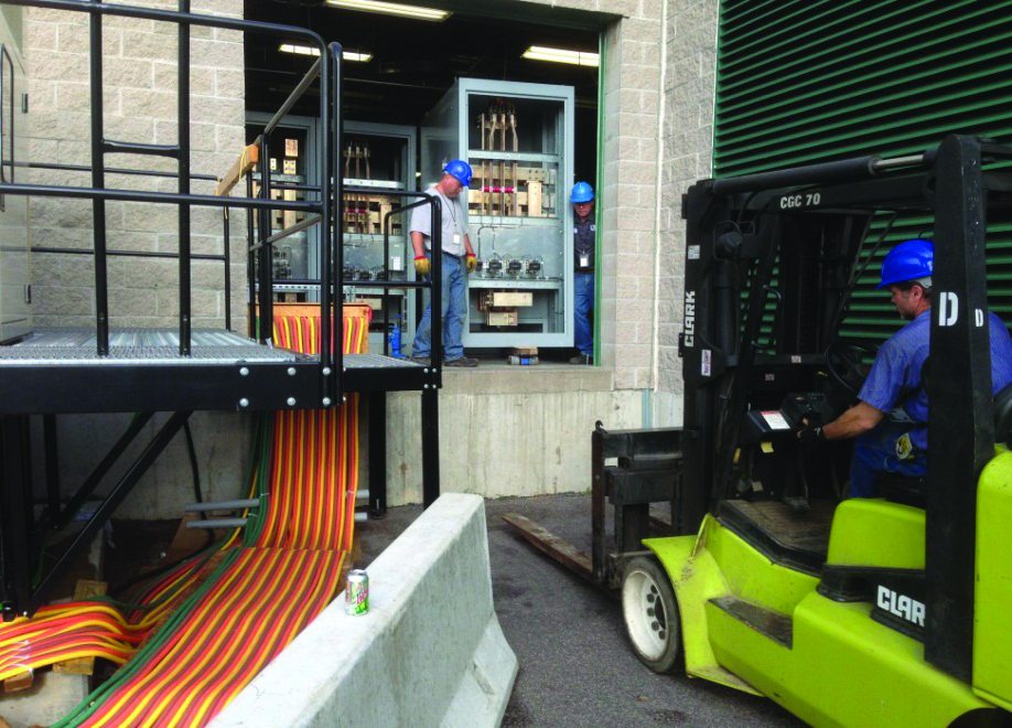
Figure 10 and 11. Old switchgear was disassembled and removed from the facility
After installation, portable load banks were brought in for commissioning the new switchgear. The engine generators also received a full re-commission due to the changes in the controls and the additional alarms.
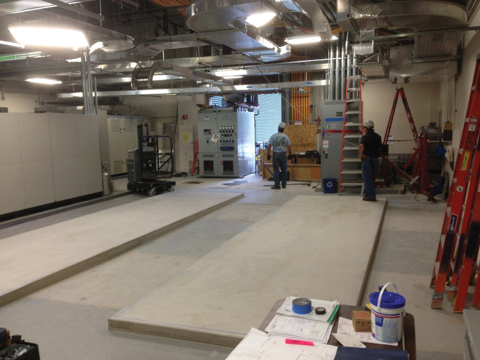

Figure 12 and 13. New switchgear was installed
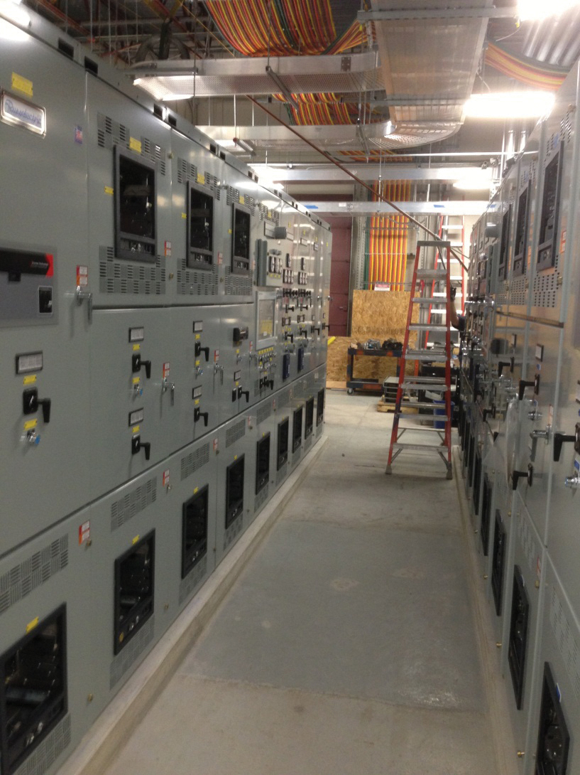
Figure 14. Switchgear supporting Yellow and Blue sides, equally dividing the critical load
After the new switchgear was fully commissioned, data center loads were cut over to the new switchgear following a similar transfer sequence as to the stand-alone power plant. The panelboards supporting mechanical and UPS equipment were again each cut over one panel at a time to keep the data center on-line, again requiring transferring data center loads to engine-generator power to isolate the data center throughout this work.
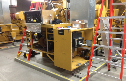
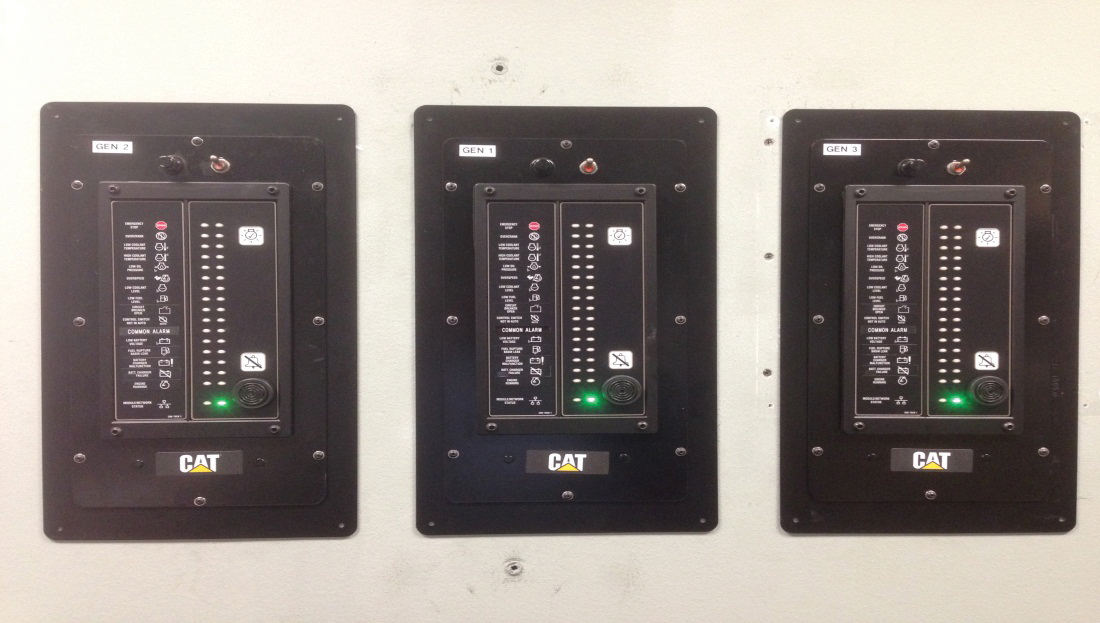
Figure 15 and 16. Upgraded engine-generator controls and alarming were installed, with panels installed in the Engineers Office
As previously mentioned, upgraded engine-generator controls and alarming were installed as part of the project (see Figures 15 and 16). The older controls had to be upgraded to allow communication with the new switchgear. Upgraded alarm panels were installed in the Engineering Office. In addition, each switchboard has a SCADA screen with a workstation installed in the Engineering Office (see Figure 17). The project also included updating MOPs for all aspects of the switchgear operation (see Figure 18).
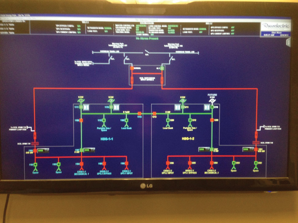
Figure 17. New switchgear includes a new SCADA system
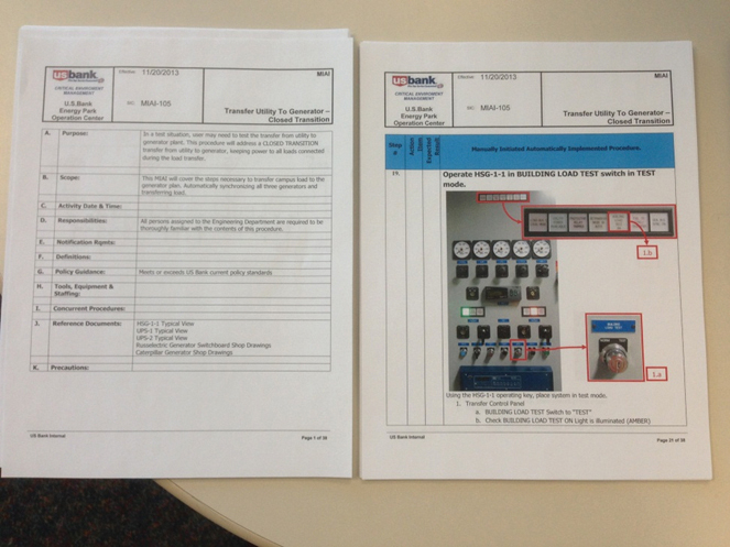
Figure 18. Updated MOPs for the switchgear
The overall project went well and was completed on time with no impact to the data center. Since this phase of the project was completed, we have performed a number of live load engine-generator tests, including a few brief utility power tests, in which the engine generators were started and supported transferred load. In each test, the new equipment performed great. Phase 2 of the modernization project is the replacement of UPS System 1, which is currently underway and anticipated to be completed later in 2014. Phase 3 is replacement of UPS System 2, scheduled for 2015.
Mark Johns
Mark Johns is chief engineer, U.S. Bank IT Critical Facilities Services. He has more than 26 years data center engineering experience, completing numerous Infrastructure upgrade projects, including all commissioning, without interruption to data center operations. Mr. John’s long career prior to U.S. Bank includes working in a 7-story multi-use facility, which includes data center operations, check processing operations, and support staff.