Peer-based critiques drive continuous improvement, identify lurking data center vulnerabilities
By Kevin Heslin
Shared information is one of the distinctive features of the Uptime Institute Network and its activities. Under non-disclosure agreements, Network members not only share information, but they also collaborate on projects of mutual interest. Uptime Institute facilitates the information sharing and helps draw conclusions and identify trends from the raw data and information submitted by members representing industries such as banking and finance, telecommunications, manufacturing, retail, transportation, government, and colocation. In fact, information sharing is required of all members.
As a result of their Network activities, longtime Network members report reduced frequency and duration of unplanned downtime in their data centers. They also say that they’ve experienced enhanced facilities and IT operations because of ideas, proven solutions, and best practices that they’ve gleaned from other members. In that way, the Network is more than the sum of its parts. Obvious examples of exclusive Network benefits include the Abnormal Incident Reports (AIRs) database , real-time Flash Reports, email inquiries, and peer-to-peer interactions at twice-annual Network conferences. No single enterprise or organization would be able to replicate the benefits created by the collective wisdom of the Network membership.
Perhaps the best examples of shared learning are the data center site tours (140 tours through the fall of 2015) held in conjunction with Network conferences. During these in-depth tours of live, technologically advanced data centers, Network members share their experiences, hear about vendor experiences, and gather new ideas—often within the facility in which they were first road tested. Ideas and observations generated during the site tours are collated during detailed follow-up discussions with the site team. Uptime Institute notes that both site hosts and guests express high satisfaction with these tours. Hosts remark that visitors raised interesting and useful observations about their data centers, and participants witness new ideas in action.
Rob Costa, Uptime Institute North America Network Director, has probably attended more Network data center tours than anyone else, first as a senior manager for The Boeing Co., and then as Network Director. In addition, Boeing and Costa hosted two tours of the company’s facilities since joining the Network in 1997. As a result, Costa is very knowledgeable about what happens during site tours and how Network members benefit.
“One of the many reasons Boeing joined the Uptime Institute Network was the opportunity to visit world-class, mission-critical data centers. We learned a lot from the tours and after returning from the conferences, we would meet with our facility partners and review the best practices and areas of improvement that we noted during the tour,” said Costa.
“We also hosted two Network tours at our Boeing data centers. The value of hosting a tour was the honest and thoughtful feedback from our peer Network members. We focused on the areas of improvement noted from the feedback sessions,” he said.
Recently, Costa noted the improvement in the quality of the data centers hosting tours, as Network members have had the opportunity to make improvements based on the lessons learned from participating in the Network. He said, “It is all about continuous improvement and the drive for zero downtime.” In addition, he has noted an increased emphasis on safety and physical security.
Fred Dickerman, Uptime Institute, Senior Vice President, Management Services, who also hosted a tour of DataSpace facilities, said, “In preparing to host a tour you tend to look at your own data center from a different point of view, which helps you to see things which get overlooked in the day to day. Basically you walk around the data center asking yourself, ‘How will others see my data center?’
Prior to the tour, Network members study design and engineering documents for the facility to get an understanding of the site’s topology.
“A manager who has had problems at a data center with smoke from nearby industrial sites entering the makeup air intakes will look at the filters on the host’s data center and suggest improvement. Managers from active seismic zones will look at your structure. Managers who have experienced a recent safety incident will look at your safety procedures, etc.” Dickerman’s perspective summarizes why normally risk-averse organizations are happy to have groups of Network members in their data centers.
Though tour participants have generated literally thousands of comments since 1994 when the first tour was held, recent data suggest that more work remains to improve facilities. In 2015, Network staff collated all the areas of improvement suggested by participants in the data center tours since 2012. In doing so, Uptime Institute counted more than 300 unique comments made in 15 loosely defined categories, with airflow management, energy efficiency, labeling, operations, risk management, and safety meriting the most attention. The power/backup power categories also received a lot of comments. Although categories such as testing, raised floor issues, and natural disasters did not receive many comments, some participants had special interest in these areas, which made the results of the tours all the more comprehensive.
Uptime Institute works with tour hosts to address all security requirements. All participants have signed non-disclosure agreements through the Network.
Dickerman suggested that the comments highlighted the fact that even the best-managed data centers have vulnerabilities. He highlighted comments related to human action (including negligence due to employee incompetence, lack of training, and procedural or management error) as significant. He also pointed out that some facilities are vulnerable because they lack contingency and emergency response plans.
Site tours last 2 hours and review the raised floor, site’s command center, switchgear, UPS systems, batteries, generators, electrical distribution, and cooling systems.
He notes that events become failures when operators respond too slowly, respond incorrectly, or don’t respond at all, whether the cause of the event is human action or natural disaster. “In almost every major technological disaster, subsequent analysis shows that timely, correct response by the responsible operators would have prevented or minimized the failure. The same is true for every serious data center failure I’ve looked at,” Dickerman said.
It should be emphasized that a lot of the recommendations deal with operations and processes, things that can be corrected in any data center. It is always nice to talk about the next data center “I would build,” but the reality is that not many people will have that opportunity. Everyone, however, can improve how they operate the site.
For example, tour participants continue to find vulnerabilities in electrical systems, perhaps because any electrical system problem may appear instantaneously, leaving little or no time to react. In addition, tour participants also continue to focus on safety, training, physical security, change management, and the presence of procedures.
In recent years, energy efficiency has become more of an issue. Related to this is the nagging sense that Operations is not making full use of management systems to provide early warning about potential problems. In addition, most companies are not using an interdisciplinary approach to improving IT efficiency.
Dickerman notes that changes in industry practices and regulations explain why comments tend to cluster in the same categories year after year. Tour hosts are very safety conscious and tend to be very proud of their safety records, but new U.S. Occupational Safety and Health Administration (OSHA) regulations limiting hot work, for example, increase pressure on facility operators to implement redundant systems that allow for the shutdown of electrical systems to enable maintenance to be performed safely. Tour participants can share experiences about how to effectively and efficiently develop appropriate procedures to track every piece of IT gear and ensure that the connectivity of the gear is known and that it is installed and plugged in correctly.
Of course, merely creating a list of comments after a walk-through is not necessarily helpful to tour hosts. Each network tour concludes with discussion where comments are compiled and discussed. Most importantly Uptime Institute staff moderate discussions, as comments are evaluated and rationales for construction and operations decisions explained. These discussions ensure that all ideas are vetted for accuracy, and that the expertise of the full group is tapped before a comment gets recorded.
Finally, Uptime Institute moderators prepare a final report for use by the tour host, so that the most valid ideas can be implemented.
Pitt Turner, Uptime Institute Executive Director Emeritus, notes that attending or hosting tours is not sufficient by itself, “There has to be motivation to improve. And people with a bias toward action do especially well. They have the opportunity to access technical ideas without worrying about cost justifications or gaining buy in. Then, when they get back to work, they can implement the easy and low-cost ideas and begin to do cost justifications on those with budget impacts.”
TESTIMONIALS
One long-time Network member illustrates that site tours are a two-way street of continuous improvement by telling two stories separated by several years and from different perspectives. “In 1999, I learned two vitally important things during a facility tour at Company A. During that tour my team saw that Company A color coded both its electrical feeds and CEVAC (command, echo, validate, acknowledge, control), which is a process that minimizes the chance for errors when executing procedures. We still color code in this way to this day.
Years later the same Network member hosted a data center tour and learned an important lesson during the site tour. “We had power distribution unit (PDU) breakers installed in the critical distribution switchgear,” he said. “We had breaker locks on the breaker handles that are used to open and close the breakers to prevent an accidental trip. I thought we had protected our breakers well, but I hadn’t noticed a very small red button at the bottom of the breaker that read ‘push to trip’ under it. A Network member brought it to my attention during a tour. I was shocked when I saw it. We now have removable plastic covers over those buttons.”
Kevin Heslin
Kevin Heslin is Chief Editor and Director of Ancillary Projects at Uptime Institute. In these roles, he supports Uptime Institute communications and education efforts. Previously, he served as an editor at BNP Media, where he founded Mission Critical, a commercial publication dedicated to data center and backup power professionals. He also served as editor at New York Construction News and CEE and was the editor of LD+A and JIES at the IESNA. In addition, Heslin served as communications manager at the Lighting Research Center of Rensselaer Polytechnic Institute. He earned the B.A. in Journalism from Fordham University in 1981 and a B.S. in Technical Communications from Rensselaer Polytechnic Institute in 2000.
https://journal.uptimeinstitute.com/wp-content/uploads/2016/06/lurkingtop.jpg4751201Kevin Heslinhttps://journal.uptimeinstitute.com/wp-content/uploads/2022/12/uptime-institute-logo-r_240x88_v2023-with-space.pngKevin Heslin2016-06-30 07:23:422016-07-01 08:24:59Identifying Lurking Vulnerabilities in the World’s Best-Run Data Centers
Will drought dry up the digital economy? With water scarcity a pressing concern, data center owners are re-examining water consumption for cooling.
By Ryan Orr and Keith Klesner
In the midst of a historic drought in the western U.S., 70% of California experienced “extreme” drought in 2015, according to the U.S. Drought Monitor.
The state’s governor issued an Executive Order requiring a 25% reduction in urban water usage compared to 2013. The Executive Order also authorizes the state’s Water Resources Control Board to implement restrictions on individual users to meet overall water savings objectives. Data centers, in large part, do not appear to have been impacted by new restrictions. However, there is no telling what steps may be deemed necessary as the state continues to push for savings.
The water shortage is putting a premium on the existing resources. In 2015, water costs in the state increased dramatically, with some customers seeing rate increases as high as 28%. California is home to many data centers, and strict limitations on industrial use would dramatically increase the cost of operating a data center in the state.
The problem in California is severe and extends beyond the state’s borders.
Population growth and climate change will create additional global water demand, so the problem of water scarcity is not going away and will not be limited to the California or even the western U.S.; it is a global issue.
On June 24, 2015, The Wall Street Journal published an article focusing on data center water usage, “Data Centers and Hidden Water Use.” With the industry still dealing with environmental scrutiny over carbon emissions, and water scarcity poised to be the next major resource to be publicly examined, IT organizations need to have a better understanding of how data centers consume water, the design choices that can limit water use, and the IT industry’s ability to address this issue.
HOW DATA CENTERS USE WATER
Data centers generally use water to aid heat rejection (i.e., cooling IT equipment). Many data centers use a water-cooled chilled water system, which distributes cool water to computer room cooling units. A fan blows across the chilled water coil, providing cool, conditioned air to IT equipment. That water then flows back to the chiller and is recooled.
Figure 1. Photo of traditional data center cooling tower
Water-cooled chiller systems rely on a large box-like unit called a cooling tower to reject heat collected by this system (see Figure 1). These cooling towers are the main culprits for water consumption in traditional data center designs. Cooling towers cool warm condenser water from the chillers by pulling ambient air in from the sides, which passes over a wet media, causing the water to evaporate. The cooling tower then rejects the heat by blowing hot, wet air out of the top. The cooled condenser water then returns back to the chiller to again accept heat to be rejected. A 1-megawatt (MW) data center will pump 855 gallons of condenser water per minute through a cooling tower, based on a design flow rate of 3 gallons per minute (GPM) per ton.
Figure 2. Cooling towers “consume” or lose water through evaporation, blow down, and drift.
Cooling towers “consume” or lose water through evaporation, blow down, and drift (see Figure 2). Evaporation is caused by the heat actually removed from the condenser water loop. Typical design practice allows evaporation to be estimated at 1% of the cooling tower water flow rate, which equates to 8.55 GPM in a fairly typical 1-MW system. Blow down describes the replacement cycle, during which the cooling tower dumps condenser water to eliminate minerals, dust, and other contaminants. Typical design practices allow for blow down to be estimated at 0.5% of the condenser water flow rate, though this could vary widely depending on the water treatment and water quality. In this example, blow down would be about 4.27 GPM. Drift describes the water that is blown away from the cooling tower by wind or from the fan. Typical design practices allow drift to be estimated at 0.005%, though poor wind protection could increase this value. In this example, drift would be practically negligible.
In total, a 1-MW data center using traditional cooling methods would use about 6.75 million gallons of water per year.
CHILLERLESS ALTERNATIVES
Many data centers are adopting new chillerless cooling methods that are more energy efficient and use less water than the chiller and cooling tower combinations. These technologies still reject heat to the atmosphere using cooling towers. However, chillerless cooling methodologies incorporate an economizer that utilizes outdoor air, which means that water is not evaporated all day long or even every day.
Some data centers use direct air cooling, which introduces outside air to the data hall, where it directly cools the IT gear without any conditioning. Christian Belady, Microsoft’s general manager for Data Center Services, once demonstrated the potential of this method by running servers for long periods in a tent. Climate, and more importantly, an organization’s willingness to accept risk of IT equipment failure due to fluctuating temperatures and airborne particulate contamination limited the use of this unusual approach. The majority of organizations that use this method do so in combination with other cooling methods.
Direct evaporative cooling employs outside air that is cooled by a water-saturated medium or via misting. A blower circulates this air to cool the servers (see Figure 3). This approach, while more common than direct outside air cooling, still exposes IT equipment to risk from outside contaminants from external events like forest fires, dust storms, agricultural activity, or construction, which can impair server reliability. These contaminants can be filtered, but many organizations will not tolerate a contamination risk.
Figure 3. Direct evaporative vs. indirect evaporative cooling
Some data centers use what is called indirect evaporative cooling. This process uses two air streams: a closed-loop air supply for IT equipment and an outside air stream that cools the primary air supply. The outside (scavenger) air stream is cooled using direct evaporative cooling. The cooled secondary air stream goes through a heat exchanger, where it cools the primary air stream. A fan circulates the cooled primary air stream to the servers.
WATERLESS ALTERNATIVES
Some existing data center cooling technologies do not evaporate water at all. Air-cooled chilled water systems do not include evaporative cooling towers. These systems are closed loop and do not use makeup water; however, they are much less energy efficient than nearly all the other cooling options, which may offset any water savings of this technology. Air-cooled systems can be fitted with water sprays to provide evaporative cooling to increase capacity and or increase cooling efficiency, but this approach is somewhat rare in data centers.
The direct expansion (DX) computer room air conditioner (CRAC) system includes a dry cooler that rejects heat via an air-to-refrigerant heat exchanger. These types of systems do not evaporate water to reject heat. Select new technologies utilize this equipment with a pumped refrigerant economizer that makes the unit capable of cooling without the use of the compressor. The resulting compressorless system does not evaporate water to cool air either, which improves both water and energy efficiency. Uptime Institute has seen these technologies operate at power usage efficiencies (PUE) of approximately 1.40, even while in full DX cooling mode, and they meet California’s strict Title 24 Building Energy Efficiency Standards.
Table 1. Energy, water, and resource costs and consumption compared for generic cooling technologies.
Table 1 compares a typical water-cooled chiller system to an air-cooled chilled water system in a 1-MW data center, assuming that the water-cooled chiller plant operates at a PUE of 1.6 and the air-cooled chiller plant operates at a PUE of 1.8 with electric rates at $0.16/kilowatt-hour (kWh) and water rates are $6/unit, with one unit being defined as 748 gallons.
The table shows that although air-cooled chillers do not consume any water they can still cost more to operate over the course of a year because water, even though a potentially scarce resource, is still relatively cheap for data center users compared to power. It is crucial to evaluate the potential offsets between energy and cooling during the design process. This analysis does not include considerations for the upstream costs or resource consumption associated with water production and energy production. However, these should also be weighed carefully against a data center’s sustainability goals.
LEADING BY EXAMPLE
Some prominent data centers using alternative cooling methods include:
• Vantage Data Centers’ Quincy, WA, site uses Munters Indirect Evaporative Cooling systems.
• Rackspace’s London data center and Digital Realty’s Profile Park facility in Dublin use roof-mounted indirect outside air technology coupled with evaporative cooling from ExCool.
• A first phase of Facebook’s Prineville, OR, data center uses direct evaporative cooling and humidification. Small nozzles attached to water pipes spray a fine mist across the air pathway, cooling the air and adding humidity. In a second phase, Facebook uses a dampened media.
• Yahoo’s upstate New York data center uses direct outside air cooling when weather conditions allow.
• Metronode, a telecommunications company in Australia, uses direct air cooling (as well as direct evaporative and DX for backup) in its facilities
• Dupont Fabros is utilizing recycled gray water for cooling towers in its Silicon Valley and Ashburn, VA, facilities. The municipal gray water supplies saves on water cost, reduces water treatment for the municipality, and reuses a less precious form of water.
Facebook reports that its Prineville cooling system uses 10% of the water of a traditional chiller and cooling tower system. ExCool claims that it requires roughly 260,000 gallons annually in a 1-MW data center, 3.3% of traditional data center water consumption, and the data centers using pumped refrigerant systems consume even less water—zero. These companies save water by eliminating evaporative technologies or by combining evaporative technologies with outside air economizers, meaning that they do not have to evaporate water 24×7.
DRAWBACKS TO LOW WATER COOLING SYSTEMS
These cooling systems can cost much more than traditional cooling systems. At current rates for water and electricity, return on investment (ROI) on these more expensive systems can take years to achieve. Compass Datacenters recently published a study showing the potential negative ROI for an evaporative cooling system.
These systems also tend take up a lot of space. For many data centers, water-cooled chiller plants make more sense because an owner can pack in a large capacity system in a relatively small footprint without modifying building envelopes.
There are also implications for data center owners who want to achieve Tier Certification. Achieving Concurrently Maintainable Tier III Constructed Facility Certification requires the isolation of each and every component of the cooling system without impact to design day cooling temperature. This means an owner needs to be able to tolerate the shutdown of cooling units, control systems, makeup water tanks and distribution, and heat exchangers. Fault Tolerance (Tier IV) requires the system to sustain operations without impact to the critical environment after any single but consequential event. While Uptime Institute has Certified many data centers that use newer cooling designs, they do add a level of complexity to the process.
Organizations also need to factor temperature considerations into their decision. If a data center is not prepared to run its server inlet air temperature at 22 degrees Celsius (72 degrees Fahrenheit) or higher, there is not much payback on the extra investment due to the fact that the potential for economization is reduced. Also, companies need to improve their computer room management, including optimizing airflow for efficient cooling, and potentially adding containment, which can drive up costs. Additionally, some of these cooling systems just won’t work in hot and humid climates.
As with any newer technology, alternative cooling systems present operations challenges. Organizations will likely need to implement new training to operate and maintain unfamiliar equipment configurations. Companies will need to conduct particularly thorough due diligence on new, proprietary vendors entering the mission critical data center space for the first time.
And last, there is significant apathy about water conservation across the data center industry as a whole. Uptime Institute survey data shows that less than one-third of data center operators track water usage or use the (WUE) metric. Furthermore, Uptime Institute’s 2015 Data Center Industry Survey found (see The Uptime Institute Journal, vol 6, p. 60) that data center operators ranked water conservation as a low priority.
But the volumes of water or power used by data centers make them easy targets for criticism. While there are good reasons to choose traditional water-cooled chilled water systems, especially when dealing with existing buildings, for new data center builds, owners should evaluate alternative cooling designs against overall business requirements, which might include sustainability factors.
Uptime Institute has invested decades of research toward reducing data center resource consumption. The water topic needs to be assessed within a larger context such as the holistic approach to efficient IT described in Uptime Institute’s Efficient IT programs. With this framework, data center operators can learn how to better justify and explain business requirements and demonstrate that they can be responsible stewards of our environment and corporate resources.
Matt Stansberry contributed to this article.
WATER SOURCES
Data centers can use water from almost any source, with the vast majority of those visited by Uptime Institute using municipal water, which typically comes from reservoirs. Other data centers use groundwater, which is precipitation that seeps down through the soil and is stored below ground. Data center operators must drill wells to access this water. However, drought and overuse are depleting groundwater tables worldwide. The United States Geological Survey has published a resource to track groundwater depletion in the U.S.
Other sources of water include rainfall, gray water, and surface water. Very few data centers use these sources for a variety of reasons. Because rainfall can be unpredictable, for instance, it is mostly collected and used as a secondary or supplemental water supply. Similarly only a handful of data centers around the world are sited near lakes, rivers, or the ocean, but those data center operators could pump water from these sources through a heat exchanger. Data centers also sometimes use a body of water for an emergency water source for cooling towers or evaporative cooling systems. Finally, gray water, which is partially treated wastewater, can be utilized as a non-potable water source for irrigation or cooling tower use. These water sources are interdependent and may be short in supply during a sustained regional drought.
Ryan Orr
Ryan Orr joined Uptime Institute in 2012 and currently serves as a senior consultant. He performs Design and Constructed Facility Certifications, Operational Sustainability Certifications, and customized Design and Operations Consulting and Workshops. Mr. Orr’s work in critical facilities includes responsibilities ranging from project engineer on major upgrades for legacy enterprise data centers, space planning for the design and construction of multiple new data center builds, and data center M&O support.
Keith Klesner
Keith Klesner is Uptime Institute’s Senior Vice President, North America. Mr. Klesner’s career in critical facilities spans 16 years and includes responsibilities ranging from planning, engineering, design, and construction to start-up and ongoing operation of data centers and mission critical facilities. He has a B.S. in Civil Engineering from the University of Colorado-Boulder and a MBA from the University of LaVerne. He maintains status as a professional engineer (PE) in Colorado and is a LEED Accredited Professional.
https://journal.uptimeinstitute.com/wp-content/uploads/2016/06/orrwaterheader.jpg4751201Kevin Heslinhttps://journal.uptimeinstitute.com/wp-content/uploads/2022/12/uptime-institute-logo-r_240x88_v2023-with-space.pngKevin Heslin2016-06-17 14:29:212016-06-17 14:29:21Ignore Data Center Water Consumption at Your Own Peril
The team approach helped the Bank earn Uptime Institute’s M&O Stamp of Approval
By Matt Stansberry
The Bank of Canada is the nation’s central bank. The Bank acts as the fiscal agent of the Canadian government, managing its public debt programs and foreign exchange reserves and setting its monetary policy. It also designs, issues, and distributes Canada’s bank notes. The Bank plays a critical role in supporting the Canadian government and Canada’s financial system. The organization manages a relatively small footprint of high-criticality data centers.
Over the last several years, the Bank has worked with Uptime Institute to significantly upgrade its data center operations framework, and it has also implemented a cross-disciplinary management team that includes stakeholders from IT, Facilities Management, and Security. The Bank adopted Uptime Institute’s Integrated Critical Environment (ICE) team concept to enhance the effectiveness of the collaboration and shared accountability framework between the three disciplines.
These efforts paid off when the Bank of Canada received a 93% score on the Uptime Institute’s M&O Assessment, which surpassed the 80% pass requirement and the 83% median score achieved by approximately 70 other accredited organizations worldwide. These scores helped the Bank achieved the M&O Stamp of Approval in October 2015.
ICE Program Project Manager Megan Murphy and ICE Program Chairperson David Schroeter explain the challenges and benefits of implementing a multidisciplinary team approach and earning the M&O Stamp of Approval from Uptime Institute.
Uptime Institute: Uptime Institute has been advocating that companies develop multidisciplinary teams for about a decade. Some leading organizations have deployed this kind of management framework, while many more still struggle with interdisciplinary communication gaps and misaligned incentives. Multidisciplinary teams are a highly effective management structure for continuously improving performance and efficiency, while increasing organizational transparency and collaboration. How has your organization deployed this team structure?
Megan Murphy: The Bank likes to shape things in its own way. Certain disciplines are near and dear to our hearts, like security. So our multidisciplinary approach integrates not just IT and Facilities but also Security and our Continuity of Operations Program.
The integrated team looks after the availability and reliability of the Bank’s critical infrastructure supporting the data center. The team is the glue that binds the different departments together, with a common objective, same language and terminologies, and unified processes. It ultimately allows us to be more resilient and nimble.
The integrated team is virtual, in that each representative reports to a home position on a day-to-day basis. The virtual team meets regularly, and representatives have the authority to make decisions on behalf of their individual stakeholder groups.
The team functions like a committee. However, where the term “committee” may sound passive; the Bank’s team functions more like a “super committee with teeth.”
David Schroeter: We come together as a committee to review and discuss changes, incidents, schedules as well as coordinate work flows. It requires a lot of effort from the individuals in these departments because of the rigor of the collaborative process, but it has paid off.
As an example, recently there was a facilities infrastructure issue. As a result of the multidisciplinary approach framework, we had the right people in the room to identify the immediate risks associated with this issue and identified that it had a significant impact on other critical infrastructure. We shifted our focus from a simple facilities repair to consider how that change might affect our overall business continuity and security posture.
This information was then quickly escalated to the Bank’s Continuity of Operations office, which activated the corporate incident management process.
It sounds like the collaboration is paying significant benefits. Why did your organization take this on?
Schroeter: Like other large corporations, our IT and Facilities teams worked within their own organizations, with their own unique perspectives and lenses. We adopted a multidisciplinary approach to bring the stakeholders together and to understand how the things they do every day will inherently impact the other groups. We realized that by not managing our infrastructure using a collaborative team approach, we were incurring needless risk to our operations.
Murphy: This concept is new to the organization, but it reflects a key tenet of the Bank’s overall vision—bringing cross-functional groups together to solve complex issues. That’s really what our team approach does.
Uptime Institute: How did you get started?
Schroeter: We used an iterative approach to develop the program through a working group and interim committee, looking at interdependencies and overlaps between our departments procedures. Gaps in our processes were revisited and addressed as required.
Murphy: We weren’t trying to reinvent things that already existed in the Bank but rather to leverage the best processes, practices, and wisdom from each department. For example, the IT department has a mature change management process in place. We took their change management template and applied it across the entire environment. Similarly we adopted Security’s comprehensive policy suite for governing and managing access control. We integrated these policies into the process framework.
Schroeter: In addition, we expanded the traditional facilities management framework to include processes to mitigate potential cyber security threats.
The multidisciplinary team allows us to continually improve, be proactive, and respond to a constantly changing environment and technology landscape.
Uptime Institute: Why did you pursue the M&O Stamp of Approval?
Murphy: It gave us a goal, a place to shoot for. Also, the M&O Stamp of Approval needs to be renewed every two years, which means we are going to be evaluated on a regular basis. So we have to stay current and continue to build on this established framework.
Schroeter: We needed a structured approach to managing the critical environment. This is not to say that our teams weren’t professional or didn’t have the competencies to do the work. But when challenged on how or why we did things, they didn’t have a consistent response.
To prepare for the M&O Assessment with Uptime Institute Consultant Richard Van Loo, we took a structured approach that encourages us to constantly look for improvements and to plan for long-term sustainability with a shared goal. It’s not just about keeping the wheels from falling off the bus. It’s about being proactive—making sure the wheels are properly balanced so it rolls efficiently.
Always looking ahead for issues rather than letting them happen.
Did you have any concerns about how you might score on the M&O Assessment?
Schroeter: We were confident that we were going to pass and pass well. We invested a significant amount of time and effort into creating the framework of the program and worked closely with Richard to help ensure that we continued on the right path as we developed documentation. Although we were tracking in the right direction and believed we would pass the assessment, we were not expecting to achieve such a high score. Ultimately our objective was to establish a robust program with a proper governance structure that could sustain operations into the future.
Uptime Institute: What was the most difficult aspect of the process?
Schroeter: Team members spent a lot of time talking to people at the Bank, advocating for the program and explaining why it matters and why it is important. We drank a lot of coffee as we built the support and relationships necessary to ensure the success of the program.
Uptime Institute: What surprised you about the assessment?
Murphy: Despite the initial growing pains that occur when any team comes together, establishing a collective goal and a sense of trust provided the team with stronger focus and clarity. Even with the day-to-day distractions and priorities and different viewpoints, the virtual team became truly integrated. This integration did not happen serendipitously; it took time, persistence, and a lot of hard work.
Uptime Institute: Did having a multidisciplinary team in place make the M&O Assessment process more or less difficult?
Murphy: The multidisciplinary approach made the M&O Assessment easier. In 2014, at the beginning of the process, there were some growing pains as the group was forming and learning how to come together. But by October 2015 when we scored the M&O Assessment, the group had solidified and team members trusted each other, having gone through the inherent ups and downs of the building process. As a result of having a cohesive team, we were confident that our management framework was strong and comprehensive as we had all collaborated and participated in the structure and its associated processes and procedures.
Having an interdisciplinary team provided us with a structured framework in which to have open and transparent discussions necessary to drive and meet the objectives our mandate.
Uptime Institute developed the concept of Integrated Critical Environments teams nearly a decade ago, encouraging organizations to adopt a combined IT-Facilities operating model. This structure became a lynchpin of M&O Stamp of Approval. During the assessment, the participant’s organizational structure is weighted very heavily to address the dangerous misperception that outages are a result of human error (the individual) while they are statistically a result of inadequate training, resource, or protocol (the organization).
Matt Stansberry
Matt Stansberry is Director of Content and Publications for the Uptime Institute and also serves as program director for the Uptime Institute Symposium, an annual event that brings together 1,500 stakeholders in enterprise IT, data center facilities, and corporate real estate to deal with the critical issues surrounding enterprise computing. He was formerly editorial director for Tech Target’s Data Center and Virtualization media group, and was managing editor of Today’s Facility Manager magazine. He has reported on the convergence of IT and facilities for more than a decade.
https://journal.uptimeinstitute.com/wp-content/uploads/2016/06/boc.jpg4751201Kevin Heslinhttps://journal.uptimeinstitute.com/wp-content/uploads/2022/12/uptime-institute-logo-r_240x88_v2023-with-space.pngKevin Heslin2016-06-01 14:07:372016-06-02 12:10:50Bank of Canada Achieves Operational Excellence
Raytheon integrates corporate sustainability to achieve savings and recognition
By Brian J. Moore
With a history of innovation spanning 92 years, Raytheon Company provides state-of-the-art electronics, mission systems integration, and other capabilities in the areas of sensing, effects, command, control, communications, and intelligence systems, as well as a broad range of mission support services in defense, civil government, and cybersecurity markets throughout the world (see Figure 1). Raytheon employs some of the world’s leading rocket scientists and more than 30,000 engineers and technologists, including over 2,000 employees focused on IT.
Figure 1. Among Raytheon’s many national defense-oriented product and solutions are sensors, radar, and other data collection systems that can be deployed as part of global analysis and aviation.
Not surprisingly, Raytheon depends a great deal on information technology (IT) as an essential enabler of its operations and as an important component of many of its products and services. Raytheon also operates a number of data centers, which support internal operations and the company’s products and services, which make up the bulk of Raytheon’s enterprise operations.
In 2010, Raytheon established an enterprise-wide IT sustainability program that gained the support of senior leadership. The program increased the company’s IT energy efficiency, which generated cost savings, contributed to the company’s sustainability goals, and enhanced the company’s reputation. Raytheon believes that its success demonstrates that IT sustainability makes sense even in companies in which IT is important, but not the central focus. Raytheon, after all, is a product and services company like many enterprises and not a hyper scale Internet company. As a result, the story of how Raytheon came to develop and then execute its IT sustainability strategy should be relevant to companies in a wide range of industries and having a variety of business models (see Figure 2).
Figure 2. Raytheon’s enterprise-wide sustainability program includes IT and its IT Sustainability Program and gives them both visibility at the company’s most senior levels.
Over the last five years the program has reduced IT power by more than 3 megawatts (MW), including 530 kilowatts (kW) in 2015. The program has also generated over US$33 million in annual cost savings, and developed processes to ensure the 100% eco-responsible management of e-waste (see Figure 3). In addition IT has developed strong working relationships related to energy management with Facilities and other functions; their combined efforts are achieving company-level sustainability goals, and IT sustainability has become an important element of the company’s culture.
Figure 3. Each year, IT sustainability efforts build upon successes of previous years. By 2015, Raytheon had identified and achieved almost 3 megawatts of IT savings.
THE IT SUSTAINABILITY OFFICE
Raytheon is proud to be among the first companies to recognize the importance of environmental sustainability, with U.S. Environmental Protection Agency (EPA) recognitions dating back to the early 1980s.
As a result, Raytheon’s IT groups across the company employed numerous people who were interested in energy savings. On their own, they began to apply techniques such as virtualization and optimizing data center airflows to save energy. Soon after its founding, Raytheon’s IT Sustainability (initially Green IT) Office, began aggregating the results of the company’s efficiencies. As a result, Raytheon saw the cumulative impact of these individual efforts and supported the Office’s efforts to do even more work.
The IT Sustainability Office coordinates a core team with representatives from the IT organizations of each of the company’s business units and a few members from Facilities. The IT Sustainability Office has a formal reporting relationship with Raytheon’s Sustainability Steering Team and connectivity with peers in other functions. Its first order of business was to develop a strategic approach to IT sustainability. The IT Sustainability Office adopted the classic military model in which developing strategy means defining the initiative’s ends, ways, and means.
Raytheon chartered the IT Sustainability Office to:
• Develop a strategic approach that defines the program’s ends, ways, and means
• Coordinate IT sustainability efforts across the lines of business and regions of the company
• Facilitate knowledge sharing and drive adoption of best practices
• Ensure alignment with senior leadership and establish and maintain connections with sustainability efforts in other functions
• Capture and communicate metrics and other results
COMMUNICATING ACROSS BUSINESS FUNCTIONS
IT energy savings tend to pay for themselves (see Figure 4), but even so, getting a persistent, comprehensive effort to achieve energy savings requires establishing a strong understanding of why energy savings are important and communicating it company wide. A strong why is needed to overcome barriers common to most organizations:
• Everyone is busy and must deal with competing priorities. Front-line data center personnel have no end of problems to resolve or improvements they would like to make, and executives know they can only focus on a limited number of goals.
• Working together across businesses and functions requires getting people out of their day-to-day rhythms and taking time to understand and be understood by others. It also requires giving up some preferred approaches for the sake of a common approach that will have the benefit of scale and integration.
• Perserverence in the face of inevitable set backs requires a deep sense of purpose and a North Star to guide continued efforts.
Figure 4. Raytheon believes that sustainability programs tend to pay for themselves, as in this hypothetical in which adjusting floor tiles and fans improved energy efficiency with no capital expenditure.
The IT Sustainability Office’s first steps were to define the ends of its efforts and to understand how its work could support larger company goals. The Sustainability Office quickly discovered that Raytheon had a very mature energy program with annual goals that its efforts would directly support. The Sustainability Office also learned about the company’s longstanding environmental sustainability program, which the EPA’s Climate Leaders program regularly recognized for its greenhouse gas reductions. The Sustainability Office’s work would support company goals in this area as well. Members of the IT Sustainability Office also learned about the positive connection between sustainability and other company objectives, including growth, employee engagement, increased innovation, and improved employee recruiting and retention.
As the full picture came into focus, the IT Sustainability Office came to understand that IT energy efficiency could have a big effect on the company’s bottom line. Consolidating a server would not only save energy by eliminating its power draw but also by reducing cooling requirements and eliminating lease charges, operational labor charges, and data center space requirements. IT staff realized that their virtualization and consolidation efforts could help Raytheon avoid building a new data center and also that their use of simple airflow optimization techniques had made it possible to avoid investments in new cooling capacity.
Having established the program’s why, the IT Sustainability Office began to define the what. It established three strategic intents:
• Operate IT as sustainably as possible
• Partner with other functions to create sustainability across the company
• Build a culture of sustainability
Of the three, the primary focus has been operating IT more sustainably. In 2010, Raytheon set 15 public sustainability goals to be accomplished by 2015. Raytheon’s Board of Directors regularly reviewed progress towards these goals. Of these, IT owned two:
1. Generate 1 MW of power savings in data centers
2. Ensure that 100% of all electronic waste is managed eco-responsibly.
IT met both of these goals and far exceeded its 1 MW power savings goal, generating just over 3 MW of power savings during this period. In addition, IT contributed to achieving several of the other company-wide goals. For example, reductions in IT power helped the company meet its goal of reducing greenhouse gas emissions. But the company’s use of IT systems also helped in less obvious ways, such as supporting efforts to manage the company’s use of substances of concern and conflict minerals in its processes and products.
This level of executive commitment became a great tool for gaining attention across the company. As IT began to achieve success with energy reductions, the IT Sustainability Office also began to establish clear tie-ins with more tactical goals, such as enabling the business to avoid building more data centers by increasing efficiencies and freeing up real estate by consolidating data centers.
The plan to partner with other functions grew from the realization that Facilities could help IT with data center energy use because a rapidly growing set of sensing, database, and analytics technologies presented a great opportunity to increase efficiencies across all of the company’s operations. Building a culture of sustainability in IT and across the company ensured that sustainability gains would increase dramatically as more employees became aware of the goals and contributed to reaching them. The IT Sustainability Office soon realized that being part of the sustainability program would be a significant motivator and source of job satisfaction for many employees.
Raytheon set new public goals for 2020. Instead of having its own energy goals, IT, Facilities, and others will work to reduce energy use by 10% more and greenhouse gas emissions an additional 12%. The company also wants to utilize 5% renewable energy. However, IT will however continue to own two public goals:
1. Deploy advanced energy management at 100% of the enterprise data centers
2. Deploy a next-generation collaboration environment across the company
THE MEANS
To execute projects such as airflow managements or virtualization that support broader objectives, the IT Sustainability Office makes use of commercially available technologies, Raytheon’s primary IT suppliers, and Raytheon’s cultural/structural resources. Most, if not all, these resources exist in most large enterprises.
Server and storage virtualization products provide the largest energy savings from a technology perspective. However, obtaining virtualization savings requires physical servers to host the virtual servers and storage and modern data center capacity to host the physical servers and storage devices. Successes achieved by the IT Sustainability Office encouraged the company leadership to upgrade infrastructure and the internal cloud computing environment necessary to support the energy-saving consolidation efforts.
The IT Sustainability Office also made use of standard data center airflow management tools such as blanking panels and worked with Facilities to deploy wireless airflow and temperature monitoring to eliminate hotspots without investing in more equipment.
In addition to hardware and software, the IT Sustainability Office leveraged the expertise of Raytheon’s IT suppliers. For example, Raytheon’s primary network supplier provided on-site consulting to help safely increase the temperature set points in network gear rooms. In addition, Raytheon is currently leveraging the expertise of its data center service provider to incorporate advanced server energy management analytics into the company’s environments.
Like all companies, Raytheon also has cultural and organizational assets that are specific to it, including:
• Governance structures that include the sustainability governance model and operating structures with IT facilitate coordination across business groups and the central IT function.
• Raytheon’s Global Communications and Advance Media Services organizations provide professional expertise for getting the company’s message out both internally and externally.
• The cultural values embedded in Raytheon’s vision, “One global team creating trusted, innovative solutions to make the world a safer place,” enable the IT Sustainability Office to get enthusiastic support from anywhere in the company when it needs it.
• An internal social media platform has enabled the IT Sustainability Office to create the “Raytheon Sustainability Community” that has nearly 1,000 self-subscribed members who discuss issues ranging from suggestions for site-specific improvements, to company strategy, to the application of solar power in their homes.
• Raytheon Six Sigma is “our disciplined, knowledge-based approach designed to increase productivity, grow the business, enhance customer satisfaction, and build a customer culture that embraces all of these goals.” Because nearly all the company’s employees have achieved one or more levels of qualification in Six Sigma, Raytheon can quickly form teams to address newly identified opportunities to reduce energy-related waste.
Raytheon’s culture of sustainability pays dividends in multiple ways. The engagement of staff outside of the IT infrastructure and operations function directly benefits IT sustainability goals. For example it is now common for non-IT engineers who work on programs supporting external customers to reach back to IT to help ensure that best practices are implemented for data center design or operation. In addition, other employees use the company’s internal social media platform to get help in establishing power settings or other appropriate means to put the computers in an energy savings mode when they notice wasteful energy use.The Facilities staff has also become very conscious of energy use in computer rooms and data closets and now know how to reach out when they notice a facility that seems to be over-cooled or otherwise running inefficiently. Finally employees now take the initiative to ensure that end-of-life electronics and consumables such as toner or batteries are disposed of properly.
There are also benefits beyond IT energy use. For many employees, the chance to engage with the company’s sustainability program and interact with like-minded individuals across the company is a major plus in their job satisfaction and sense of pride in working for the company. Human Resources values this result so much that it highlight’s Raytheon’s sustainability programs and culture in its recruiting efforts.
Running a sustainability program like this, over time also requires close attention to governance. In addition to having a cross-company IT Sustainability Office, Raytheon formally includes sustainability at each of the three levels of the company sustainability governance model (see Figure 5). A council with membership drawn from senior company leadership provides overall direction and maintains the connection; a steering team comprising functional vice-presidents meets quarterly to track progress, set goals, and make occasional course corrections; and the working team level is where the IT Sustainability Office connects with peer functions and company leadership. This enterprise governance model initially grew out of an early partnership between IT and Facilities that had been formed to address data center energy issues.
Figure 5. Raytheon includes sustainability in each of its three levels of governance.
Reaching out across the enterprise, the IT Sustainability Office includes representatives from each business unit who meet regularly to share knowledge, capture and report metrics, and work common issues. This structure enabled Raytheon to build a company-wide community of practice, which enabled it to sustain progress over multiple years and across the entire enterprise.
At first, the IT Sustainability Office included key contacts within each line of business who formed a working team that established and reported metrics, identified and shared best practices, and championed the program within their business. Later, facility engineers and more IT staff would be added to the working team, so that it became the basis for a larger community of practice that would meet occasionally to discuss particular topics or engage a broader group in a project. Guest speakers and the company’s internal social media platform are used to maintain the vitality of this team.
As a result of this evolution, the IT Sustainability Office eventually established partnership relationships with Facilities; Environment, Health and Safety; Supply Chain; Human Resources; and Communications at both the corporate and business levels. These partnerships enabled Raytheon to build energy and virtualization reviews into its formal software development methodology. This makes the software more likely to run in an energy-efficient manner and also easier for internal and external customers to use the software in a virtualized environment.
THE WAYS
The fundamental ways of reducing IT energy use are well known:
• Virtualizing servers and storage allows individual systems to support multiple applications or images, making greater use of the full capabilities of the IT equipment and executing more workloads in less space with less energy
• Identifying and decommissioning servers that are not performing useful work has immediate benefits that become significant when aggregated
• Optimizing airflows, temperature set points, and other aspects of data center facility operations often have very quick paybacks
• Data center consolidation, moving from more, older, less-efficient facilities to fewer, higher efficiency data centers typically reduces energy use and operating costs while also increasing reliability and business resilience
After establishing the ends and the ways, the next step was getting started. Raytheon’s IT Sustainability Office found that establishing goals that aligned with those of leadership was a way to establish credibility at all levels across the company, which was critical to developing initial momentum. Setting targets, however, was not enough to maintain this credibility. The IT Sustainability Office found it necessary to persistently apply best practices at scale across multiple sectors of the company. As a result, IT Sustainability Office devised means to measure, track, and report progress against the goals. The metrics had to be meaningful and realistic, but also practical.
In some cases, measuring energy savings is a straightforward task. When facility engineers are engaged in enhancing the power and cooling efficiency of a single data center, their analyses typically include a fairly precise estimate of expected power savings. In most cases the scale of the work will justify installing meters to gather the needed data. It is also possible to do a precise engineering analysis of the energy savings that come from rehosting a major enterprise resource planning (ERP) environment or a large storage array.
On the other hand, it is much harder to get a precise measurement for each physical server that is eliminated or virtualized at enterprise scale. Though it is generally easy to get power usage for any one server, it is usually not cost effective to measure and capture this information for hundreds or thousands of servers having varying configurations and diverse workloads, especially when the servers operate in data centers of varying configurations and efficiencies.
The IT Sustainability Office instead developed a standard energy savings factor that could be used to provide a valid estimate of power savings when applied to the number of servers taken out of operation. To establish the factor, the IT Sustainability Office did a one-time study of the most common servers in the company’s Facilities and developed a conservative consensus on the net energy savings that result from replacing them with a virtual server.
The factor multiplies an average net plug savings of 300 watts (W) by a Power Usage Effectiveness (PUE) of 2.0, which was both an industry average at that time and a decent estimate of the average across Raytheon’s portfolio of data centers. Though in many cases actual plug power savings exceed 300 W, having a conservative number that could be easily applied allowed for effective metric collection and for communicating the value being achieved. The team also developed a similar factor for cost savings, which took into account hardware lease expense and annual operating costs. These factors, while not precise, were conservative and sufficient to report tens of millions of dollars in cost savings to senior management, and were used thoughout the five-year long pursuit of the company’s 2015 sustainability goal. To reflect current technology and environmental factors, these energy and cost savings factors are being updated in conjunction with setting new goals.
EXTERNAL RECOGNITION
The IT Sustainability Office also saw that external recognition helps build and maintain momentum for the sustainability program. For example, in 2015 Raytheon won a Brill Award for Energy Efficiency from Uptime Institute. In previous years, Raytheon received awards from Computerworld, InfoWorld, Homeland Security Today, and e-stewards. In addition, Raytheon’s CIO appeared on a CNBC People and Planet feature and was recognized by Forrester and ICEX for creating an industry benchmark.
Internal stakeholders, including senior leadership, noted this recognition. The awards increased their awareness of the program and how it was reducing costs, supporting company sustainability goals, and contributing to building the company’s brand. When Raytheon’s CEO mentioned the program and the two awards it won that year at a recent annual shareholders meeting, the program instantly gained credibility.
In addition to IT-specific awards, the IT Sustainability Office’s efforts to partner led it to support company-level efforts to gain recognition for the company’s other sustainability efforts, including providing content each year for Raytheon’s Corporate Responsibility Report and for its application for the EPA Climate Partnership Award. This partnership strategy leads the team to work closely with other functions on internal communications and training efforts.
For instance, the IT Sustainability Office developed one of the six modules in the company’s Sustainability Star program, which recognizes employee efforts and familiarizes them with company sustainability initiatives. The team also regularly provides content for intranet-based news stories, supports campaigns related to Earth Day and Raytheon’s Energy Month, and hosts the Raytheon Sustainabilty Community.
Brian J. Moore
Brian J. Moore is senior principal information systems technologist in the Raytheon Company’s Information Technology (IT) organization in Global Business Services. The Raytheon Company, with 2015 sales of $23 billion and 61,000 employees worldwide, is a technology and innovation leader specializing in defense, security, and civil markets throughout the world. Raytheon is headquartered in Waltham, MA. The Raytheon IT Sustainability Office, which Moore leads, focuses on making IT operations as sustainable as possible, partnering with other functions to leverage IT to make their business processes more sustainable, and creating a culture of sustainability. Since he initiated this program in 2008, it has won six industry awards, including, most recently, the 2015 Brill Award for IT Energy Efficiency from Uptime Institute. Moore was also instrumental in creating Raytheon’s sustainability governance model and in setting the company’s public sustainability goals.
How insights from Tier Certification of Constructed Facilities avoids unforeseen costs and errors for all new projects
By Kevin Heslin
Uptime Institute’s Tier Classification System has been a part of the data center industry lexicon for 20 years. Since its creation in the mid-1990s, the system has evolved into the global standard for third-party validation of data center critical infrastructure. At the same time, misconceptions about the Tier program confuse the industry and make it harder for a data center team to understand and prepare sufficiently for the rigors of the Tier process. Fortunately, Uptime Institute provides guidance and plenty of opportunity for clients to prepare for a Tier Certification well before the on-site review of functionality demonstrations.
This article discusses the Tier Certification process in more detail, specifically explaining the on-site demonstration portion of a Tier Certification. This is a highly rigorous process that requires preparation.
Uptime Institute consultants notice that poor preparation for a Tier Certification of Constructed Facility signals that serious problems will be uncovered during the facility demonstration. Resolving problems at this late stage may require a second site visit or even expensive mechanical and electrical changes. These delays may also cause move-in dates to be postponed. In other situations, the facility may not qualify for the Certification at the specified and expected design load.
TIER CERTIFICATION–HOW IT WORKS
Tier Certification is a performance-based evaluation of a data center’s specific infrastructure and not a checklist or cookbook. The process ensures that the owner’s facility has been constructed as designed and verifies that it is capable of meeting the defined availability requirements. Even the best laid plans can go awry, and common construction phase practices or value engineering proposals can compromise the design intent of a data center (See “Avoiding Data Center Construction Problems” by Keith Klesner, The Uptime Institute Journal, vol 5, p. 6).
The site visit provides an opportunity to observe whether the staff is knowledgeable about the facility and has practiced the demonstrations.
With multiple vendors, subcontractors, and typically more than 50 different disciplines involved in any data center project—structural, electrical, HVAC, plumbing, fuel pumps, networking, and more—it would be remarkable if there were no errors or unintended risks introduced during the construction process.
The Tier Certification typically starts with a company deploying new data center capacity. The data center owner defines a business requirement to achieve a specific Tier (I-IV) level to ensure the asset meets performance capacity, effectiveness, and reliability requirements. Only Uptime Institute can certify that a data center design and/or constructed facility does, in fact, meet the owner’s Tier objective.
The first step is the Tier Certification of Design Documents. Uptime Institute consultants review 100% of the design documents, ensuring that each and every electrical, mechanical, monitoring, and automation subsystem meets the Tier objective requirements. Uptime Institute reports its findings to the owner, noting any Tier deficiencies. It is then up to the owner’s team to revise the drawings to address those deficiencies.
After Uptime Institute consultants determine that the revised design drawings correct the deficiencies, the Tier Certification of Design Documents foil may be awarded.
Immediately after the Design Certification is awarded, the Facility Certification begins when Uptime Institute consultants begin devising a list of demonstrations to be performed by site staff upon the conclusion of Level 5 Commissioning. Uptime Institute consultants provide the demonstrations to the client in advance and are available to answer questions throughout the construction process. In addition, Uptime Institute has created an instructional presentation for each Tier Level, so that owners can better understand the process and how to prepare for the site visit.
Fortunately, Uptime Institute provides guidance and plenty of opportunity for clients to prepare for a Facility Certification well before the on-site review of functionality demonstrations. Uptime Institute Senior Vice President, Tier Standards, Chris Brown said, “From my perspective a successful Facility Certification is one in which the clients are well prepared and all systems meet Tier requirements the first time. They have all their documents and planning done. And, pretty much everything goes without a hitch.”
Planning for the Facility Certification begins early in the construction process. Clients must schedule adequate time for Level 5 Commissioning and the site visit, ensuring that construction delays and cost overruns do not compromise time for either the commissioning or Certification process. They will also want to make sure that vendors and contractors will have the right personnel on site during the Certification visit.
Tier Certification of Constructed Facility:
• Ensures that a facility has been constructed as designed
• Verifies a facility’s capability to meet the defined availability requirements
• Follows multiple mechanical and electrical criteria as defined in the Tier Standard: Topology
• Seamlessly integrates into the project schedule
• Ensures that deficiencies in the design are identified, solved, and tested before operations commence
• Includes live system demonstrations under real-world conditions, validating performance according to the
facility’s Tier objective
• Conducts demonstrations specifically tailored to the exact topology of the data center
A team of Uptime Institute consultants will visit the site for 3-5 days, generally a little more than a month after construction of critical systems ends, allowing plenty of time for commissioning. While on site, the team identifies discrepancies between the design drawings and installed equipment. They also observe the results of each demonstration.
PREPARATIONS FOR TIER CERTIFICATION DEMONSTRATIONS
The value of Tier Certification comes from finding and eliminating blind spots, points of failure, and weak points before a site is fully operational and downtime results.
In an ideal scenario, data center facilities teams would have successfully completed Level 5 Commissioning (Integrated System Testing). The commissioning testing would have already exercised all of the components as though the data center were operational. That means that load banks simulating IT equipment are installed in the data center to fully test the power and cooling. The systems are operated together to ensure that the data center operates as designed in all specified maintenance and failure scenarios.
Everything should be running exactly as specified, and changes from the design should be minimal and insignificant. In fact, facility personnel should be familiar with the facility and its operation and may even have practiced the demonstrations during commissioning.
“Clients who are prepared have fully commissioned the site and they have put together the MOPs and SOPs (operating procedures) for the work that is required to actually accomplish the demonstrations,” said Chris Brown, Uptime Institute Senior Vice President, Tier Standards. “They have the appropriate technical staff on site. And, they have practiced or rehearsed the demonstrations before we get there.
“Because we typically come in for site visit immediately following Level 5 Commissioning, we ask for a commissioning schedule, and that will give us an indication of how rigorous commissioning has been and give us an idea of whether this is going to be a successful facility certification or not.”
Once on site, Uptime Institute consultants observe the Operations team as it performs the different demonstrations, such as interrupting the incoming utility power supply to see that the UPS carries the critical load until the engine generators come on line and provide power to the data center and that the cooling system maintains the critical load during the transition.
Integrated systems testing requires load banks to simulate live IT equipment to test how the data center power and cooling systems perform under operating conditions.
Other demonstrations include removing redundant capacity components from service and showing that, for example, N engine generators can support the data center critical load or that the redundant chilled water distribution loop can be removed from service while still sufficiently cooling the data center.
“Some of these demonstrations take time, especially those involving the cooling systems,” Brown said.
The client must prepare properly because executing the demonstrations in a timely manner requires that the client:
1. Create a schedule and order of demonstrations
2. Create all procedures required to complete the functionality demonstrations
3. Provide necessary technical support personnel
a. Technicians
b. Installers
c. Vendors
4. Provide, install, and operate load banks
5. Direct on-site technical personnel
6. Provide means to measure the presence of voltage on electrical devices during isolation by qualified personnel.
Even though the assessment evaluates the physical topology and equipment, organizations need proper staffing, training, and documentation in place to ensure the demonstrations are performed successfully.
AVOID TIER CERTIFICATION HORROR STORIES
Fundamentally, the Tier Certification process is a binary exercise. The data center facility is compliant with its stated Tier objective, or it is not. So, why then, do Uptime Institute consultants sometimes experience a sinking feeling upon arriving at a site and meeting the team?
Frequently, within the first moments at the facility, it is obvious to the Uptime Institute consultant that nothing is as it should be and the next several days are going to be difficult ones.
Uptime Institute consultants can often tell at first glance whether the client has met the guidance to prepare for the Tier Certification. In fact, the consultants will often know a great deal from the number and tone of questions regarding the demonstrations list.
“You can usually tell if the client has gone through the demonstration list,” said Uptime Institute Consultant Eric Maddison. “I prepare the demonstration list from schematics, so they are not listed in order. It is the client’s obligation to sequence them logically. So it is a good sign if the client has sequenced the demonstrations logically and prepared a program with timing and other information on how they are to perform the demonstration.”
Similarly, Uptime Institute consultants can see whether technicians and appropriate load banks are available. “You can walk into a data hall and see how the load banks are positioned and get a pretty good sense for whether there will be a problem or not,” Brown said, “If the facility has a 1,200-kilowatt load and they only have two large load banks, that’s a dead giveaway that the load banks are too large and not in the right place.”
Similarly, a few quick conversations will tell whether a client has arranged appropriate staffing for the demonstrations. The facility tour provides plenty of opportunity to observe whether the staff on site is knowledgeable about the facility and has practiced the demonstrations. The appropriate level of staff varies from site to site with the complexity of the data center. But, the client needs to have people on site who understand the overall design and can operate each individual piece of equipment as well as respond to unexpected failures or performance issues.
Brown recalled one facility tour that included 25 people, but only two had any familiarity with the site. He said, “Relying on a headcount is not possible; we need to understand who the people are and their backgrounds.
“We start with an in-brief meeting the morning of the first day for every Tier Certification and that usually takes about an hour, and then we do a tour of the facility, which can take anywhere from 2-4 hours, depending on the size of the facility. By the time those are finished, we have a pretty good idea of whether they are in the A, B, C, or D range of preparation. You start to worry if no one can answer the questions you pose, or if they don’t really have a plan or schedule for demonstrations. You can also get a good comfortable feeling if everybody has the answers, and they know where the equipment is and how it works.”
During this first day, the consultants will also determine who the client liaison is, meet the whole client team, and go over the goals of the program and site visit. During the site tour, the consultants will familiarize themselves with the facility, verify it looks as expected, check that valves and breakers are in place, and confirm equipment nameplates.
Having the proper team on site requires a certain amount of planning. Brown said that owners often inadvertently cause a big challenge by letting contractors and vendors go before the site visit. “They’ve done the construction, they’ve done the operations, and they’ve done the commissioning,” he said, “But then the Operations team comes in cold on Monday after everyone else has left. The whole brain trust that knows how the facility systems work and operate just left the site. And there’s a stack of books and binders 2-feet long for the Operations guys to read, good luck.”
Brown described a much better scenario in which the Uptime Institute consultants arrive on site and find, “The Operations team ready to go and the processes and procedures are already written. They are ready to take over on Day 1 and remain in place for 20 years. They can roll through the demonstrations. And they have multiple team members checking each other, just like they were doing maintenance for 5 years together.
“During the demonstrations, they are double checking process and procedures. ‘Oh wait,’ they’ll say, ‘we need to do this.’ They will update the procedure and do the demonstration again. In this case, the site is going to be ready to handover and start working the Monday after we leave. And everybody’s there still trying to finish up that last little bit of understanding the data center, and see that the process and procedures have all the information they need to effectively operate for years to come.”
In these instances, the owner would have positioned the Operations staff in place early in the project, whether that role is filled by a vendor or in-house staff.
In one case, a large insurer staffed a new facility by transferring half the staff from an existing data center and hiring the rest. That way, it had a mix of people who knew the company’s systems and knew how things worked. They were also part of the commissioning process. The experienced people could then train the new hires.
During the demonstration, the team will interrupt the incoming utility power supply and see that the UPS carries the critical load until the engine generators come on line and provide power to the data center and that the cooling system maintains the critical load during the transition.
WHAT CAUSES POOR PERFORMANCE DURING TIER CERTIFICATION?
So with all these opportunities to prepare, why do some Tier Certifications become difficult experiences?
Obviously, lack of preparation tops the list. Brown said, “Often, there’s hubris. ‘I am a savvy owner, and therefore, the construction team knows what they are doing, and they’ll get it right the first time.’” Similarly, clients do not always understand that the Tier Certification is not a rubber stamp. Maddison recalled more than one instance when he arrived on site only to find the site unprepared to actually perform any of the demonstrations.
Failure to understand the isolation requirements, incomplete drawings, design changes made after the Design Certification, and incomplete or abbreviated commissioning can cause headaches too. Achieving complete isolation of equipment, in particular, has proven to be challenging for some owners.
Sometimes clients aren’t familiar with all the features of a product, but more often the client will open the breakers and think it is isolated. Similar situations can arise when closing valves to confirm that a chilled water system is Concurrently Maintainable or Fault Tolerant.
Incomplete or changed drawings are a key source of frustration. Brown recalled one instance when the Tier Certified Design Documents did not show a generator control. And, since each and every system must meet the Tier requirement, the “new” equipment posed a dilemma, as no demonstration had been devised.
More common, though, are changes to design drawings. Brown said, “During every construction there are going to be changes from what’s designed to what’s built; sometimes there are Tier implications. And, these are not always communicated to us, so we discover them on the site visit.”
Poor commissioning will also cause site visit problems. Brown said, “A common view is that commissioning is turning everything on to see if it works. They’ll say, ‘Well we killed the utility power and the generator started. We have some load in there.’ They just don’t understand that load banking only the generator isn’t commissioning.”
He cites an instance in which the chillers weren’t provided the expected cooling. It turned out that cooling tubes were getting clogged by dirt and silt. “There’s no way they did commissioning—proper commissioning—or they would have noticed that.”
Construction delays can compromise commissioning. As Brown said, “Clients expect to have a building handed over on a certain date. Of course there are delays in construction, delays in commissioning, and delays because equipment didn’t work properly when it was first brought in. For any number of reasons the schedule can be pushed. And the commissioning just gets reduced in scope to meet that same schedule.”
Very often, then, the result is that owner finds that the Tier Certification cannot be completed because not everything has been tested thoroughly and things are not working as anticipated.
If the commissioning is compromised or the staff is not prepared, can the facility pass the Tier Certification anyway?
The short answer is yes.
But often these problems are indications of deeper issues that indicate a facility may not meet the performance requirements of the owner, require expensive mechanical and electrical changes, or cause move-in dates to be postponed–or some combination of all three. In these instances, failing the Tier Certification at the specified and expected time may be the least of the owner’s worries.
In these instances and many others, Uptime Institute consultants can—and do—offer useful advice and solutions. Communication is the key because each circumstance is different. In some cases, the solutions, including multiple site visits, can be expensive. In other cases, however, something like a delayed client move-in date can be worked out by rescheduling a site visit.
In addition, Maddison points out the well-prepared clients can manage the expected setbacks that might occur during the site visit. “Often more compartmentalization is needed or more control strategy. Some clients work miracles. They move control panels or put in new breakers overnight.”
But, successful outcomes like that must be planned. Asking questions, preparing Operations teams, scheduling and budgeting for Commissioning, and understanding the value of the Tier Certification can lead to a smooth process and a facility that meets or exceeds client requirements.
The aftermath of a smooth site visit should almost be anticlimactic. Uptime Institute consultants will prepare a Tier Certification Memorandum documenting any remaining issues, listing any documents to be updated, and describing the need for possible follow-on site visits.
And then finally, upon successful completion of the process, the owner receives the Tier Certification of Constructed Facility letter, an electronic foil, and plaque attesting to the performance of the facility.
Uptime Institute’s Chris Brown, Eric Maddison, and Ryan Orr contributed to this article.
Kevin Heslin is Chief Editor and Director of Ancillary Projects at Uptime Institute. In these roles, he supports Uptime Institute communications and education efforts. Previously, he served as an editor at BNP Media, where he founded Mission Critical, a commercial publication dedicated to data center and backup power professionals. He also served as editor at New York Construction News and CEE and was the editor of LD+A and JIES at the IESNA. In addition, Heslin served as communications manager at the Lighting Research Center of Rensselaer Polytechnic Institute. He earned the B.A. in Journalism from Fordham University in 1981 and a B.S. in Technical Communications from Rensselaer Polytechnic Institute in 2000.
https://journal.uptimeinstitute.com/wp-content/uploads/2016/05/head.jpg4751201Kevin Heslinhttps://journal.uptimeinstitute.com/wp-content/uploads/2022/12/uptime-institute-logo-r_240x88_v2023-with-space.pngKevin Heslin2016-05-11 13:44:582016-05-11 13:53:25Avoid Failure and Delay on Capital Projects: Lessons from Tier Certification
HPC supercomputing and traditional enterprise IT facilities operate very differently
By Andrey Brechalov
In recent years, the need to solve complex problems in science, education, and industry, including the fields of meteorology, ecology, mining, engineering, and others, has added to the demand for high-performance computing (HPC). The result is the rapid development of HPC systems, or supercomputers, as they are sometimes called. The trend shows no signs of slowing, as the application of supercomputers is constantly expanding. Research today requires ever more detailed modeling of complex physical and chemical processes, global atmospheric phenomena, and distributed systems behavior in dynamic environments. Supercomputer modeling provides fine results in these areas and others, with relatively low costs.
Supercomputer performance can be described in petaflops (pflops), with modern systems operating at tens of pflops. However, performance improvements cannot be achieved solely by increasing the number of existing computing nodes in a system, due to weight, size, power, and cost considerations. As a result, designers of supercomputers attempt to improve their performance by optimizing their architecture and components, including interconnection technologies (networks) and by developing and incorporating new types of computing nodes having greater computational density per unit of area. These higher-density nodes require the use of new (or well-forgotten old) and highly efficient methods of removing heat. All this has a direct impact on the requirements for site engineering infrastructure.
HPC DATA CENTERS
Supercomputers can be described as a collection of interlinked components and assemblies—specialized servers, network switches, storage devices, and links between the system and the outside world. All this equipment can be placed in standard or custom racks, which require conditions of power, climate, security, etc., to function properly—just like the server-based IT equipment found in more conventional facilities.
Low- or medium-performance supercomputers can usually be placed in general purpose data centers and even in server rooms, as they have infrastructure requirements similar to other IT equipment, except for a bit higher power density. There are even supercomputers for workgroups that can be placed directly in an office or lab. In most cases, however, any data center designed to accommodate high power density zones should be able to host one of these supercomputers.
On the other hand, powerful supercomputers usually get placed in dedicated rooms or even buildings that include unique infrastructure optimized for a specific project. These facilities are pretty similar to general-purpose data centers. However, dedicated facilities for powerful supercomputers host a great deal of high power density equipment, packed closely together. As a result, these facilities must make use of techniques suitable for removing the higher heat loads. In addition, the composition and characteristics of IT equipment for an HPC data center are already known before the site design begins and its configuration does not change or changes only subtly during its lifetime, except for planned expansions. Thus it is possible to define the term HPC data center as a data center intended specifically for placement of a supercomputer.
Figure 1. Types of HPC data center IT equipment
The IT equipment in a HPC data center built using the currently popular cluster-based architecture can be generally divided into two types, each having its own requirements for engineering infrastructure Fault Tolerance and component redundancy (see Figure 1 and Table 1).
Table 1. Types of IT equipment located in HPC data centers
The difference in the requirements for redundancy for the two types of IT equipment is because applications running on a supercomputer usually have a reduced sensitivity to failures of computational nodes, interconnection leaf switches, and other computing equipment (see Figure 2). These differences enable HPC facilities to incorporate segmented infrastructures that meet the different needs of the two kinds of IT equipment.
Figure 2. Generic HPC data center IT equipment and engineering infrastructure.
ENGINEERING INFRASTRUCTURE FOR COMPUTATIONAL EQUIPMENT
Supercomputing computational equipment usually incorporates cutting-edge technologies and has extremely high power density. These features affect the specific requirements for engineering infrastructure. In 2009, the number of processors that were placed in one standard 42U (19-inch rack unit) cabinet at Moscow State University’s (MSU) Lomonosov Data Center was more than 380, each having a thermal design power (TDP) of 95 watts for a total of 36 kilowatts (kW/rack). Adding 29 kW/rack for auxiliary components, such as (e.g. motherboards, fans, and switches brings the total power requirement to 65 kW/rack. Since then the power density for such air-cooled equipment has reached 65 kW/rack.
On the other hand, failures of computing IT equipment do not cause the system as a whole to fail because of the cluster technology architecture of supercomputers and software features. For example, job checkpointing and automated job restart software features enable applications to isolate computing hardware failures and the computing tasks management software ensures that applications use only operational nodes even when some faulty or disabled nodes are present. Therefore, although failures in engineering infrastructure segments that serve computational IT equipment increase the time required to perform computing tasks, these failures do not lead to a catastrophic loss of data.
Supercomputing computational equipment usually operates on single or N+1 redundant power supplies, with the same level of redundancy throughout the electric circuit to the power input. In the case of a single hardware failure, segmentation of the IT loads and supporting equipment limits the effects of the failure to only a part of IT equipment.
Customers often refuse to install standby-rated engine-generator sets, completely relying on utility power. In these cases, the electrical system design is defined by the time required for normal IT equipment shutdown and the UPS system mainly rides through brief power interruptions (a few minutes) in utility power.
Cooling systems are designed to meet similar requirements. In some cases, owners will lower redundancy and increase segmentation without significant loss of operational qualities to optimize capital expense (CapEx) and operations expense (OpEx). However, the more powerful supercomputers expected in the next few years will require the use of technologies, including partial or full liquid cooling, with greater heat removal capacity.
OTHER IT EQUIPMENT
Auxiliary IT equipment in a HPC data center includes air-cooled servers (sometimes as part of blade systems), storage systems, and switches in standard 19-inch racks that only rarely reach the power density level of 20 kW/rack. Uptime Institute’s annual Data Center Survey reports that typical densities are less than 5 kW/rack.
This equipment is critical to cluster functionality; and therefore, usually has redundant power supplies (most commonly N+2) that draw power from independent sources. Whenever hardware with redundant power is applied, the rack’s automatic transfer switches (ATS) are used to ensure the power failover capabilities. The electrical infrastructure for this equipment is usually designed to be Concurrently Maintainable, except that standby-rated engine-generator sets are not always specified. The UPS system is designed to provide sufficient time and energy for normal IT equipment shutdown.
The auxiliary IT equipment must be operated in an environment cooled to 18–27°C, (64–81°F) according to ASHRAE recommendations, which means that solutions used in general data centers will be adequate to meet the heat load generated by this equipment. These solutions often meet or exceed Concurrent Maintainability or Fault Tolerant performance requirements.
ENERGY EFFICIENCY
In recent years, data center operators have put a greater priority on energy efficiency. This focus on energy saving also applies to specialized HPC data centers. Because of the numerous similarities between the types of data centers, the same methods of improving energy efficiency are used. These include the use of various combinations of free cooling modes, higher coolant and set point temperatures, economizers, evaporative systems, and variable frequency drives and pumps as well as numerous other technologies and techniques.
Reusing the energy used by servers and computing equipment is one of the most promising of these efficiency improvements. Until recent years, all that energy had been dissipated. Moreover, based on average power usage efficiency (PUE), even efficient data centers must use significant energy to dissipate the heat they generate.
Facilities that include chillers and first-generation liquid cooling systems generate “low potential heat” [coolant temperatures of 10–15°C (50–59°F), 12–17°C (54–63°F), and even 20–25°C (68–77°F)] that can be used rather than dissipated, but doing so requires significant CapEx and OpEx (e.g., use of heat pumps) that lead to long investment return times that are usually considered unacceptable.
Increasing the heat potential of the liquid coolants improves the effectiveness of this approach, absent direct expansion technologies. And even while reusing the heat load is not very feasible in server-based spaces, there have been positive applications in supercomputing computational spaces. Increasing the heat potential can create additional opportunities to use free cooling in any climate. That allows year-round free cooling in the HPC data center is a critical requirement.
A SEGMENTED HPC DATA CENTER
Earlier this year the Russian company T-Platforms deployed the Lomonosov-2 supercomputer at MSU, using the segmented infrastructure approach. T-Platforms has experience in supercomputer design and complex HPC data center construction in Russia and abroad. When T-Platforms built the first Lomonosov supercomputer, it scored 12th in the global TOP500 HPC ratings. Lomonosov-1 has been used at 100% of its capacity with about 200 tasks waiting in job queue on average. The new supercomputer will significantly expand MSU’s Supercomputing Center capabilities.
The engineering systems for the new facility were designed to support the highest supercomputer performance, combining new and proven technologies to create an energy-efficient scalable system. The engineering infrastructure for this supercomputer was completed in June 2014, and the computing equipment is being gradually added to the system, as requested by MSU. The implemented infrastructure allows system expansion with currently available A-Class computing hardware and perspective generations of IT equipment without further investments in the engineering systems.
THE COMPUTATIONAL SEGMENT
The supercomputer is based on T-Platforms’s A-class high-density computing system and makes use of a liquid cooling system (see Figure 3). A-class supercomputers support designs of virtually any scale. The peak performance of one A-class enclosure is 535 teraflops (tflops) and a system based on it can easily be extended up to more than 100 pflops. For example, the combined performance of the five A-class systems already deployed at MSU reached 2,576 tflops in 2014 (22nd in the November 2014 TOP500) and was about 2,675 tflops in July 2015. This is approximately 50% greater than the peak performance of the entire first Lomonosov supercomputer (1,700 tflops, 58th in the same TOP500 edition). A supercomputer made of about 100 A-class enclosures would perform on par with the Tianhe-2 (Milky Way-2) system at National Supercomputer Center in Guangzhou (China) that leads the current TOP500 list at about 55 pflops.
Figure 3. The supercomputer is based on T-Platforms’s A-class high-density computing system and makes use of a liquid cooling system
All A-class subsystems, including computing and service nodes, switches, and cooling and power supply equipment, are tightly integrated in a single enclosure as modules with hot swap support (including those with hydraulic connections). The direct liquid cooling system is the key feature of the HPC data center infrastructure. It almost completely eliminates air as the medium of heat exchange. This solution improves the energy efficiency of the entire complex by making these features possible:
• IT equipment installed in the enclosure has no fans
• Heat from the high-efficiency air-cooled power supply units (PSU) is removed using water/air heat exchangers embedded in the enclosure
• Electronic components in the cabinet do not require computer room air for cooling
• Heat dissipated to the computer room is minimized because the cabinet is sealed and insulated
• Coolant is supplied to the cabinet at cabinet at 44°C (111°F) with up to 50°C (122°F) outbound under full load, which enables year-round free cooling at ambient summer temperatures of up to 35°C (95°F) and the use of dry coolers without adiabatic systems (see Figure 4)
Figure 4. Coolant is supplied to the auxiliary IT cabinets at 44°C (50°C outbound under full load), which enables year-round free cooling at ambient summer temperatures of up to 35°C and the use of dry coolers without adiabatic systems
In addition noise levels are also low because liquid cooling eliminates powerful node fans that generate noise in air-cooled systems. The only remaining fans in A-Class systems are embedded in the PSUs inside the cabinets, and these fans are rather quiet. Cabinet design contains most of the noise from this source.
INFRASTRUCTURE SUPPORT
The power and cooling systems for Lomonosov-2 follow the general segmentation guidelines. In addition, they must meet the demands of the facility’s IT equipment and engineering systems at full load, which includes up to 64 A-class systems (peak performance over 34 pflops) and up to 80 auxiliary equipment U racks in 42U, 48U, and custom cabinets. At full capacity these systems require 12,000-kW peak electric power capacity.
Utility power is provided by eight 20/0.4-kV substations, each having two redundant power transformers making a total of 16 low-voltage power lines with a power limit of 875 kW/line in normal operation.
Although no backup engine-generator sets have been provisioned, at least 28% of the computing equipment and 100% of auxiliary IT equipment is protected by UPS providing at least 10 minutes of battery life for all connected equipment.
The engineering infrastructure also includes two independent cooling systems: a warm-water, dry-cooler type for the computational equipment and a cold-water, chiller system for auxiliary equipment. These systems are designed for normal operation in temperatures ranging from -35 to+35°C (-31 to +95°F) with year-round free cooling for the computing hardware. The facility also contains an emergency cooling system for auxiliary IT equipment.
The facility’s first floor includes four 480-square-meters (m2) rooms for computing equipment (17.3 kW/m2) and four 280-m2 rooms for auxiliary equipment (3 kW/m2) with 2,700 m2 for site engineering rooms on an underground level.
POWER DISTRIBUTION
The power distribution system is built on standard switchboard equipment and is based on the typical topology for general data centers. In this facility, however, the main function of the UPS is to ride through brief blackouts of the utility power supply for select computing equipment (2,340 kW), all auxiliary IT equipment (510 kW), and engineering equipment systems (1,410 kW). In the case of a longer blackout, the system supplies power for proper shutdown of connected IT equipment.
The UPS system is divided into three independent subsystems. The first is for computing equipment, the second is for auxiliary equipment, and the third is for engineering systems. In fact, the UPS system is deeply segmented because of the large number of input power lines. This minimizes the impact of failures of engineering equipment on supercomputer performance in general.
The segmentation principle is also applied to the physical location of the power supply equipment. Batteries are placed in three separate rooms. In addition, there are three UPS rooms and one switchboard room for the computing equipment that is unprotected by UPS. Figure 5 shows one UPS-battery room pair.
Figure 5. A typical pair of UPS-battery rooms
Three, independent, parallel UPS, each featuring N+1 redundancy (see Figure 6), feed the protected computing equipment. This redundancy, along with bypass availability and segmentation, simplifies UPS maintenance and the task of localizing a failure. Considering that each UPS can receive power from two mutually redundant transformers, the overall reliability of the system meets the owner’s requirements.
Figure 6. Power supply plan for computing equipment
Three independent parallel UPS systems are also used for the auxiliary IT equipment because it requires greater failover capabilities. The topology incorporates a distributed redundancy scheme that was developed in the late 1990s. The topology is based on use of three or more UPS modules with independent input and output feeders (see Figure 7).
Figure 7. Power supply for auxiliary equipment
This system is more economical than a 2N-redundant configuration while providing the same reliability and availability levels. Cable lines connect each parallel UPS to the auxiliary equipment computer rooms. Thus, the computer room has three UPS-protected switchboards. The IT equipment in these rooms, being mostly dual fed, is divided into three groups, each of which is powered by two switchboards. Single-feed and N+1 devices are connected through a local rack-level ATS (see Figure 8).
Figure 8. Single-feed and N+1-redundant devices are connected through a local rack-level ATS
ENGINEERING EQUIPMENT
Some of the engineering infrastructure also requires uninterrupted power in order to provide the required Fault Tolerance. The third UPS system meets this requirement. It consists of five completely independent single UPSs. Technological redundancy is fundamental. Redundancy is applied not to the power lines and switchboard equipment but directly to the engineering infrastructure devices.
The number of UPSs in the group (Figure 9 shows three of five) determines the maximum redundancy to be 4+1. This system can also provide 3+2 and 2N configurations). Most of the protected equipment is at N+1 (see Figure 9).
Figure 9. Power supply for engineering equipment
In general, this architecture allows decommissioning of any power supply or cooling unit, power line, switchboard, UPS, etc., without affecting the serviced IT equipment. Simultaneous duplication of power supply and cooling system components is not necessary.
OVERALL COOLING SYSTEM
Lomonosov-2 makes use of a cooling system that consists of two independent segments, each of which is designed for its own type of IT equipment (see Table 2). Both segments make use of a two-loop scheme with plate heat exchangers between loops. The outer loops have a 40% ethylene-glycol mixture that is used for coolant. Water is used in the inner loops. Both segments have N+1 components (N+2 for dry coolers in the supercomputing segment).
Table 2. Lomonosov makes use of a cooling system that consists of two independent segments, each of which is designed to meet the different requirements of the supercomputing and auxiliary IT equipment.
This system, designed to serve the 64 A-class enclosures, has been designated the hot-water segment. Its almost completely eliminates the heat from extremely energy-intensive equipment without chillers (see Figure 10). Dry coolers dissipate all the heat that is generated by the supercomputing equipment up to ambient temperatures of 35°C (95°F). Power is required only for the circulation pumps of both loops, dry cooler fans, and automation systems.
Figure 10. The diagram shows the cooling system’s hot water segment.
Under full load and in the most adverse conditions, the instant PUE would be expected to be about 1.16 for the fully deployed system of 64 A-class racks (see Figure 11).
Figure 11. Under full load and under the most adverse conditions, the instant PUE (power utilization efficiency would be expected to be about 1.16 for the fully deployed system of 64 A-class racks)
The water in the inner loop has been purified and contains corrosion inhibitors. It is supplied to computer rooms that will contain only liquid-cooled computer enclosures. Since the enclosures do not use computer room air for cooling, the temperature in these rooms is set at 30°C (86°F) and can be raised to 40°C (104°F) without any influence on the equipment performance. The inner loop piping is made of PVC/CPVC (polyvinyl chloride/chlorinated polyvinyl chloride) thus avoiding electrochemical corrosion.
COOLING AUXILIARY IT EQUIPMENT
It is difficult to avoid using air-cooled IT equipment, even in a HPC project, so MSU deployed a separate cold-water [12–17°C (54–63°F)] cooling system. The cooling topology in these four spaces is almost identical to the hot-water segment deployed in the A-class rooms, except that chillers are used to dissipate the excess heat from the auxiliary IT spaces to the atmosphere. In the white spaces, temperatures are maintained using isolated Hot Aisles and in-row cooling units. Instant PUE for this isolated system is about 1.80, which is not a particularly efficient system (see Figure 12).
Figure 12. In white spaces, temperatures are maintained using isolated hot aisles and in-row cooling units.
If necessary, some of the capacity of this segment can be used to cool the air in the A-class computing rooms. The capacity of the cooling system in these spaces can meet up to 10% of the total heat inflow in each of the A-class enclosures. Although sealed, they still heat the computer room air through convection. But in fact, passive heat radiation from A-class enclosures is less than 5% of the total power consumed by them.
EMERGENCY COOLING
An emergency-cooling mode exists to deal with utility power input blackouts, when both cooling segments are operating on power from the UPS. In emergency mode, each cooling segment has its own requirements. As all units in the first segment (both pump groups, dry coolers, and automation) are connected to the UPS, the system continues to function until the batteries discharge completely.
In the second segment, the UPS services only the inner cooling loop pumps, air conditioners in computer rooms, and automation equipment. The chillers and outer loop pumps are switched off during the blackout.
Since the spaces allocated for cooling equipment are limited, it was impossible to use a more traditional method of stocking cold water at the outlet of the heat exchangers (see Figure 13). Instead, the second segment of the emergency system features accumulator tanks with water stored at a lower temperature than in the loop [about 5°C (41°F) with 12°C (54°F) in the loop] to keep system parameters within a predetermined range. Thus, the required tank volume was reduced to 24 cubic meters (m3) instead of 75 m3, which allowed the equipment to fit in the allocated area. A special three-way valve allows mixing of chilled water from the tanks into the loop if necessary. Separate small low-capacity chillers (two 55-kW chillers) are responsible for charging the tanks with cold water. The system charges the cold-water tanks in about the time it takes to charge the UPS batteries.
Figure 13. Cold accumulators are used to keep system parameters within a predetermined range.
MSU estimates that segmented cooling with a high-temperature direct water cooling segment reduces its total cost of ownership by 30% compared to data center cooling architectures based on direct expansion (DX) technologies. MSU believes that this project shows that combining the most advanced and classical technologies and system optimization allows significant savings on CapEx and OpEx while keeping the prerequisite performance, failover, reliability and availability levels.
Andrey Brechalov
Andrey Brechalov is Chief Infrastructure Solutions Engineer of T-Platforms, a provider of high performance computing (HPC) systems, services, and solutions headquartered in Moscow, Russia. Mr. Brechalov has responsibility for building engineering infrastructures for supercomputers SKIF K-1000, SKIF Cyberia, and MSU Lomonosov-2 as well as smaller supercomputers by T-Platforms. He has worked for more than 20 years in computer industry including over 12 years in HPC and specializes in designing, building, and running supercomputer centers.
https://journal.uptimeinstitute.com/wp-content/uploads/2016/01/moscow.jpg4751201Kevin Heslinhttps://journal.uptimeinstitute.com/wp-content/uploads/2022/12/uptime-institute-logo-r_240x88_v2023-with-space.pngKevin Heslin2016-01-29 08:57:492016-01-29 08:57:49Moscow State University Meets HPC Demands
Identifying Lurking Vulnerabilities in the World’s Best-Run Data Centers
/in Executive, Operations/by Kevin HeslinPeer-based critiques drive continuous improvement, identify lurking data center vulnerabilities
By Kevin Heslin
Shared information is one of the distinctive features of the Uptime Institute Network and its activities. Under non-disclosure agreements, Network members not only share information, but they also collaborate on projects of mutual interest. Uptime Institute facilitates the information sharing and helps draw conclusions and identify trends from the raw data and information submitted by members representing industries such as banking and finance, telecommunications, manufacturing, retail, transportation, government, and colocation. In fact, information sharing is required of all members.
As a result of their Network activities, longtime Network members report reduced frequency and duration of unplanned downtime in their data centers. They also say that they’ve experienced enhanced facilities and IT operations because of ideas, proven solutions, and best practices that they’ve gleaned from other members. In that way, the Network is more than the sum of its parts. Obvious examples of exclusive Network benefits include the Abnormal Incident Reports (AIRs) database , real-time Flash Reports, email inquiries, and peer-to-peer interactions at twice-annual Network conferences. No single enterprise or organization would be able to replicate the benefits created by the collective wisdom of the Network membership.
Perhaps the best examples of shared learning are the data center site tours (140 tours through the fall of 2015) held in conjunction with Network conferences. During these in-depth tours of live, technologically advanced data centers, Network members share their experiences, hear about vendor experiences, and gather new ideas—often within the facility in which they were first road tested. Ideas and observations generated during the site tours are collated during detailed follow-up discussions with the site team. Uptime Institute notes that both site hosts and guests express high satisfaction with these tours. Hosts remark that visitors raised interesting and useful observations about their data centers, and participants witness new ideas in action.
Rob Costa, Uptime Institute North America Network Director, has probably attended more Network data center tours than anyone else, first as a senior manager for The Boeing Co., and then as Network Director. In addition, Boeing and Costa hosted two tours of the company’s facilities since joining the Network in 1997. As a result, Costa is very knowledgeable about what happens during site tours and how Network members benefit.
“One of the many reasons Boeing joined the Uptime Institute Network was the opportunity to visit world-class, mission-critical data centers. We learned a lot from the tours and after returning from the conferences, we would meet with our facility partners and review the best practices and areas of improvement that we noted during the tour,” said Costa.
“We also hosted two Network tours at our Boeing data centers. The value of hosting a tour was the honest and thoughtful feedback from our peer Network members. We focused on the areas of improvement noted from the feedback sessions,” he said.
Recently, Costa noted the improvement in the quality of the data centers hosting tours, as Network members have had the opportunity to make improvements based on the lessons learned from participating in the Network. He said, “It is all about continuous improvement and the drive for zero downtime.” In addition, he has noted an increased emphasis on safety and physical security.
Fred Dickerman, Uptime Institute, Senior Vice President, Management Services, who also hosted a tour of DataSpace facilities, said, “In preparing to host a tour you tend to look at your own data center from a different point of view, which helps you to see things which get overlooked in the day to day. Basically you walk around the data center asking yourself, ‘How will others see my data center?’
Prior to the tour, Network members study design and engineering documents for the facility to get an understanding of the site’s topology.
“A manager who has had problems at a data center with smoke from nearby industrial sites entering the makeup air intakes will look at the filters on the host’s data center and suggest improvement. Managers from active seismic zones will look at your structure. Managers who have experienced a recent safety incident will look at your safety procedures, etc.” Dickerman’s perspective summarizes why normally risk-averse organizations are happy to have groups of Network members in their data centers.
Though tour participants have generated literally thousands of comments since 1994 when the first tour was held, recent data suggest that more work remains to improve facilities. In 2015, Network staff collated all the areas of improvement suggested by participants in the data center tours since 2012. In doing so, Uptime Institute counted more than 300 unique comments made in 15 loosely defined categories, with airflow management, energy efficiency, labeling, operations, risk management, and safety meriting the most attention. The power/backup power categories also received a lot of comments. Although categories such as testing, raised floor issues, and natural disasters did not receive many comments, some participants had special interest in these areas, which made the results of the tours all the more comprehensive.
Uptime Institute works with tour hosts to address all security requirements. All participants have signed non-disclosure agreements through the Network.
Dickerman suggested that the comments highlighted the fact that even the best-managed data centers have vulnerabilities. He highlighted comments related to human action (including negligence due to employee incompetence, lack of training, and procedural or management error) as significant. He also pointed out that some facilities are vulnerable because they lack contingency and emergency response plans.
Site tours last 2 hours and review the raised floor, site’s command center, switchgear, UPS systems, batteries, generators, electrical distribution, and cooling systems.
He notes that events become failures when operators respond too slowly, respond incorrectly, or don’t respond at all, whether the cause of the event is human action or natural disaster. “In almost every major technological disaster, subsequent analysis shows that timely, correct response by the responsible operators would have prevented or minimized the failure. The same is true for every serious data center failure I’ve looked at,” Dickerman said.
It should be emphasized that a lot of the recommendations deal with operations and processes, things that can be corrected in any data center. It is always nice to talk about the next data center “I would build,” but the reality is that not many people will have that opportunity. Everyone, however, can improve how they operate the site.
For example, tour participants continue to find vulnerabilities in electrical systems, perhaps because any electrical system problem may appear instantaneously, leaving little or no time to react. In addition, tour participants also continue to focus on safety, training, physical security, change management, and the presence of procedures.
In recent years, energy efficiency has become more of an issue. Related to this is the nagging sense that Operations is not making full use of management systems to provide early warning about potential problems. In addition, most companies are not using an interdisciplinary approach to improving IT efficiency.
Dickerman notes that changes in industry practices and regulations explain why comments tend to cluster in the same categories year after year. Tour hosts are very safety conscious and tend to be very proud of their safety records, but new U.S. Occupational Safety and Health Administration (OSHA) regulations limiting hot work, for example, increase pressure on facility operators to implement redundant systems that allow for the shutdown of electrical systems to enable maintenance to be performed safely. Tour participants can share experiences about how to effectively and efficiently develop appropriate procedures to track every piece of IT gear and ensure that the connectivity of the gear is known and that it is installed and plugged in correctly.
Of course, merely creating a list of comments after a walk-through is not necessarily helpful to tour hosts. Each network tour concludes with discussion where comments are compiled and discussed. Most importantly Uptime Institute staff moderate discussions, as comments are evaluated and rationales for construction and operations decisions explained. These discussions ensure that all ideas are vetted for accuracy, and that the expertise of the full group is tapped before a comment gets recorded.
Finally, Uptime Institute moderators prepare a final report for use by the tour host, so that the most valid ideas can be implemented.
Pitt Turner, Uptime Institute Executive Director Emeritus, notes that attending or hosting tours is not sufficient by itself, “There has to be motivation to improve. And people with a bias toward action do especially well. They have the opportunity to access technical ideas without worrying about cost justifications or gaining buy in. Then, when they get back to work, they can implement the easy and low-cost ideas and begin to do cost justifications on those with budget impacts.”
TESTIMONIALS
One long-time Network member illustrates that site tours are a two-way street of continuous improvement by telling two stories separated by several years and from different perspectives. “In 1999, I learned two vitally important things during a facility tour at Company A. During that tour my team saw that Company A color coded both its electrical feeds and CEVAC (command, echo, validate, acknowledge, control), which is a process that minimizes the chance for errors when executing procedures. We still color code in this way to this day.
Years later the same Network member hosted a data center tour and learned an important lesson during the site tour. “We had power distribution unit (PDU) breakers installed in the critical distribution switchgear,” he said. “We had breaker locks on the breaker handles that are used to open and close the breakers to prevent an accidental trip. I thought we had protected our breakers well, but I hadn’t noticed a very small red button at the bottom of the breaker that read ‘push to trip’ under it. A Network member brought it to my attention during a tour. I was shocked when I saw it. We now have removable plastic covers over those buttons.”
Kevin Heslin
Kevin Heslin is Chief Editor and Director of Ancillary Projects at Uptime Institute. In these roles, he supports Uptime Institute communications and education efforts. Previously, he served as an editor at BNP Media, where he founded Mission Critical, a commercial publication dedicated to data center and backup power professionals. He also served as editor at New York Construction News and CEE and was the editor of LD+A and JIES at the IESNA. In addition, Heslin served as communications manager at the Lighting Research Center of Rensselaer Polytechnic Institute. He earned the B.A. in Journalism from Fordham University in 1981 and a B.S. in Technical Communications from Rensselaer Polytechnic Institute in 2000.
Ignore Data Center Water Consumption at Your Own Peril
/in Executive/by Kevin HeslinWill drought dry up the digital economy? With water scarcity a pressing concern, data center owners are re-examining water consumption for cooling.
By Ryan Orr and Keith Klesner
In the midst of a historic drought in the western U.S., 70% of California experienced “extreme” drought in 2015, according to the U.S. Drought Monitor.
The state’s governor issued an Executive Order requiring a 25% reduction in urban water usage compared to 2013. The Executive Order also authorizes the state’s Water Resources Control Board to implement restrictions on individual users to meet overall water savings objectives. Data centers, in large part, do not appear to have been impacted by new restrictions. However, there is no telling what steps may be deemed necessary as the state continues to push for savings.
The water shortage is putting a premium on the existing resources. In 2015, water costs in the state increased dramatically, with some customers seeing rate increases as high as 28%. California is home to many data centers, and strict limitations on industrial use would dramatically increase the cost of operating a data center in the state.
The problem in California is severe and extends beyond the state’s borders.
Population growth and climate change will create additional global water demand, so the problem of water scarcity is not going away and will not be limited to the California or even the western U.S.; it is a global issue.
On June 24, 2015, The Wall Street Journal published an article focusing on data center water usage, “Data Centers and Hidden Water Use.” With the industry still dealing with environmental scrutiny over carbon emissions, and water scarcity poised to be the next major resource to be publicly examined, IT organizations need to have a better understanding of how data centers consume water, the design choices that can limit water use, and the IT industry’s ability to address this issue.
HOW DATA CENTERS USE WATER
Data centers generally use water to aid heat rejection (i.e., cooling IT equipment). Many data centers use a water-cooled chilled water system, which distributes cool water to computer room cooling units. A fan blows across the chilled water coil, providing cool, conditioned air to IT equipment. That water then flows back to the chiller and is recooled.
Figure 1. Photo of traditional data center cooling tower
Water-cooled chiller systems rely on a large box-like unit called a cooling tower to reject heat collected by this system (see Figure 1). These cooling towers are the main culprits for water consumption in traditional data center designs. Cooling towers cool warm condenser water from the chillers by pulling ambient air in from the sides, which passes over a wet media, causing the water to evaporate. The cooling tower then rejects the heat by blowing hot, wet air out of the top. The cooled condenser water then returns back to the chiller to again accept heat to be rejected. A 1-megawatt (MW) data center will pump 855 gallons of condenser water per minute through a cooling tower, based on a design flow rate of 3 gallons per minute (GPM) per ton.
Figure 2. Cooling towers “consume” or lose water through evaporation, blow down, and drift.
Cooling towers “consume” or lose water through evaporation, blow down, and drift (see Figure 2). Evaporation is caused by the heat actually removed from the condenser water loop. Typical design practice allows evaporation to be estimated at 1% of the cooling tower water flow rate, which equates to 8.55 GPM in a fairly typical 1-MW system. Blow down describes the replacement cycle, during which the cooling tower dumps condenser water to eliminate minerals, dust, and other contaminants. Typical design practices allow for blow down to be estimated at 0.5% of the condenser water flow rate, though this could vary widely depending on the water treatment and water quality. In this example, blow down would be about 4.27 GPM. Drift describes the water that is blown away from the cooling tower by wind or from the fan. Typical design practices allow drift to be estimated at 0.005%, though poor wind protection could increase this value. In this example, drift would be practically negligible.
In total, a 1-MW data center using traditional cooling methods would use about 6.75 million gallons of water per year.
CHILLERLESS ALTERNATIVES
Many data centers are adopting new chillerless cooling methods that are more energy efficient and use less water than the chiller and cooling tower combinations. These technologies still reject heat to the atmosphere using cooling towers. However, chillerless cooling methodologies incorporate an economizer that utilizes outdoor air, which means that water is not evaporated all day long or even every day.
Some data centers use direct air cooling, which introduces outside air to the data hall, where it directly cools the IT gear without any conditioning. Christian Belady, Microsoft’s general manager for Data Center Services, once demonstrated the potential of this method by running servers for long periods in a tent. Climate, and more importantly, an organization’s willingness to accept risk of IT equipment failure due to fluctuating temperatures and airborne particulate contamination limited the use of this unusual approach. The majority of organizations that use this method do so in combination with other cooling methods.
Direct evaporative cooling employs outside air that is cooled by a water-saturated medium or via misting. A blower circulates this air to cool the servers (see Figure 3). This approach, while more common than direct outside air cooling, still exposes IT equipment to risk from outside contaminants from external events like forest fires, dust storms, agricultural activity, or construction, which can impair server reliability. These contaminants can be filtered, but many organizations will not tolerate a contamination risk.
Figure 3. Direct evaporative vs. indirect evaporative cooling
Some data centers use what is called indirect evaporative cooling. This process uses two air streams: a closed-loop air supply for IT equipment and an outside air stream that cools the primary air supply. The outside (scavenger) air stream is cooled using direct evaporative cooling. The cooled secondary air stream goes through a heat exchanger, where it cools the primary air stream. A fan circulates the cooled primary air stream to the servers.
WATERLESS ALTERNATIVES
Some existing data center cooling technologies do not evaporate water at all. Air-cooled chilled water systems do not include evaporative cooling towers. These systems are closed loop and do not use makeup water; however, they are much less energy efficient than nearly all the other cooling options, which may offset any water savings of this technology. Air-cooled systems can be fitted with water sprays to provide evaporative cooling to increase capacity and or increase cooling efficiency, but this approach is somewhat rare in data centers.
The direct expansion (DX) computer room air conditioner (CRAC) system includes a dry cooler that rejects heat via an air-to-refrigerant heat exchanger. These types of systems do not evaporate water to reject heat. Select new technologies utilize this equipment with a pumped refrigerant economizer that makes the unit capable of cooling without the use of the compressor. The resulting compressorless system does not evaporate water to cool air either, which improves both water and energy efficiency. Uptime Institute has seen these technologies operate at power usage efficiencies (PUE) of approximately 1.40, even while in full DX cooling mode, and they meet California’s strict Title 24 Building Energy Efficiency Standards.
Table 1. Energy, water, and resource costs and consumption compared for generic cooling technologies.
Table 1 compares a typical water-cooled chiller system to an air-cooled chilled water system in a 1-MW data center, assuming that the water-cooled chiller plant operates at a PUE of 1.6 and the air-cooled chiller plant operates at a PUE of 1.8 with electric rates at $0.16/kilowatt-hour (kWh) and water rates are $6/unit, with one unit being defined as 748 gallons.
The table shows that although air-cooled chillers do not consume any water they can still cost more to operate over the course of a year because water, even though a potentially scarce resource, is still relatively cheap for data center users compared to power. It is crucial to evaluate the potential offsets between energy and cooling during the design process. This analysis does not include considerations for the upstream costs or resource consumption associated with water production and energy production. However, these should also be weighed carefully against a data center’s sustainability goals.
LEADING BY EXAMPLE
Some prominent data centers using alternative cooling methods include:
• Vantage Data Centers’ Quincy, WA, site uses Munters Indirect Evaporative Cooling systems.
• Rackspace’s London data center and Digital Realty’s Profile Park facility in Dublin use roof-mounted indirect outside air technology coupled with evaporative cooling from ExCool.
• A first phase of Facebook’s Prineville, OR, data center uses direct evaporative cooling and humidification. Small nozzles attached to water pipes spray a fine mist across the air pathway, cooling the air and adding humidity. In a second phase, Facebook uses a dampened media.
• Yahoo’s upstate New York data center uses direct outside air cooling when weather conditions allow.
• Metronode, a telecommunications company in Australia, uses direct air cooling (as well as direct evaporative and DX for backup) in its facilities
• Dupont Fabros is utilizing recycled gray water for cooling towers in its Silicon Valley and Ashburn, VA, facilities. The municipal gray water supplies saves on water cost, reduces water treatment for the municipality, and reuses a less precious form of water.
Facebook reports that its Prineville cooling system uses 10% of the water of a traditional chiller and cooling tower system. ExCool claims that it requires roughly 260,000 gallons annually in a 1-MW data center, 3.3% of traditional data center water consumption, and the data centers using pumped refrigerant systems consume even less water—zero. These companies save water by eliminating evaporative technologies or by combining evaporative technologies with outside air economizers, meaning that they do not have to evaporate water 24×7.
DRAWBACKS TO LOW WATER COOLING SYSTEMS
These cooling systems can cost much more than traditional cooling systems. At current rates for water and electricity, return on investment (ROI) on these more expensive systems can take years to achieve. Compass Datacenters recently published a study showing the potential negative ROI for an evaporative cooling system.
These systems also tend take up a lot of space. For many data centers, water-cooled chiller plants make more sense because an owner can pack in a large capacity system in a relatively small footprint without modifying building envelopes.
There are also implications for data center owners who want to achieve Tier Certification. Achieving Concurrently Maintainable Tier III Constructed Facility Certification requires the isolation of each and every component of the cooling system without impact to design day cooling temperature. This means an owner needs to be able to tolerate the shutdown of cooling units, control systems, makeup water tanks and distribution, and heat exchangers. Fault Tolerance (Tier IV) requires the system to sustain operations without impact to the critical environment after any single but consequential event. While Uptime Institute has Certified many data centers that use newer cooling designs, they do add a level of complexity to the process.
Organizations also need to factor temperature considerations into their decision. If a data center is not prepared to run its server inlet air temperature at 22 degrees Celsius (72 degrees Fahrenheit) or higher, there is not much payback on the extra investment due to the fact that the potential for economization is reduced. Also, companies need to improve their computer room management, including optimizing airflow for efficient cooling, and potentially adding containment, which can drive up costs. Additionally, some of these cooling systems just won’t work in hot and humid climates.
As with any newer technology, alternative cooling systems present operations challenges. Organizations will likely need to implement new training to operate and maintain unfamiliar equipment configurations. Companies will need to conduct particularly thorough due diligence on new, proprietary vendors entering the mission critical data center space for the first time.
And last, there is significant apathy about water conservation across the data center industry as a whole. Uptime Institute survey data shows that less than one-third of data center operators track water usage or use the (WUE) metric. Furthermore, Uptime Institute’s 2015 Data Center Industry Survey found (see The Uptime Institute Journal, vol 6, p. 60) that data center operators ranked water conservation as a low priority.
But the volumes of water or power used by data centers make them easy targets for criticism. While there are good reasons to choose traditional water-cooled chilled water systems, especially when dealing with existing buildings, for new data center builds, owners should evaluate alternative cooling designs against overall business requirements, which might include sustainability factors.
Uptime Institute has invested decades of research toward reducing data center resource consumption. The water topic needs to be assessed within a larger context such as the holistic approach to efficient IT described in Uptime Institute’s Efficient IT programs. With this framework, data center operators can learn how to better justify and explain business requirements and demonstrate that they can be responsible stewards of our environment and corporate resources.
Matt Stansberry contributed to this article.
WATER SOURCES
Data centers can use water from almost any source, with the vast majority of those visited by Uptime Institute using municipal water, which typically comes from reservoirs. Other data centers use groundwater, which is precipitation that seeps down through the soil and is stored below ground. Data center operators must drill wells to access this water. However, drought and overuse are depleting groundwater tables worldwide. The United States Geological Survey has published a resource to track groundwater depletion in the U.S.
Other sources of water include rainfall, gray water, and surface water. Very few data centers use these sources for a variety of reasons. Because rainfall can be unpredictable, for instance, it is mostly collected and used as a secondary or supplemental water supply. Similarly only a handful of data centers around the world are sited near lakes, rivers, or the ocean, but those data center operators could pump water from these sources through a heat exchanger. Data centers also sometimes use a body of water for an emergency water source for cooling towers or evaporative cooling systems. Finally, gray water, which is partially treated wastewater, can be utilized as a non-potable water source for irrigation or cooling tower use. These water sources are interdependent and may be short in supply during a sustained regional drought.
Ryan Orr
Ryan Orr joined Uptime Institute in 2012 and currently serves as a senior consultant. He performs Design and Constructed Facility Certifications, Operational Sustainability Certifications, and customized Design and Operations Consulting and Workshops. Mr. Orr’s work in critical facilities includes responsibilities ranging from project engineer on major upgrades for legacy enterprise data centers, space planning for the design and construction of multiple new data center builds, and data center M&O support.
Keith Klesner
Keith Klesner is Uptime Institute’s Senior Vice President, North America. Mr. Klesner’s career in critical facilities spans 16 years and includes responsibilities ranging from planning, engineering, design, and construction to start-up and ongoing operation of data centers and mission critical facilities. He has a B.S. in Civil Engineering from the University of Colorado-Boulder and a MBA from the University of LaVerne. He maintains status as a professional engineer (PE) in Colorado and is a LEED Accredited Professional.
Bank of Canada Achieves Operational Excellence
/in Executive, Operations/by Kevin HeslinThe team approach helped the Bank earn Uptime Institute’s M&O Stamp of Approval
By Matt Stansberry
The Bank of Canada is the nation’s central bank. The Bank acts as the fiscal agent of the Canadian government, managing its public debt programs and foreign exchange reserves and setting its monetary policy. It also designs, issues, and distributes Canada’s bank notes. The Bank plays a critical role in supporting the Canadian government and Canada’s financial system. The organization manages a relatively small footprint of high-criticality data centers.
Over the last several years, the Bank has worked with Uptime Institute to significantly upgrade its data center operations framework, and it has also implemented a cross-disciplinary management team that includes stakeholders from IT, Facilities Management, and Security. The Bank adopted Uptime Institute’s Integrated Critical Environment (ICE) team concept to enhance the effectiveness of the collaboration and shared accountability framework between the three disciplines.
These efforts paid off when the Bank of Canada received a 93% score on the Uptime Institute’s M&O Assessment, which surpassed the 80% pass requirement and the 83% median score achieved by approximately 70 other accredited organizations worldwide. These scores helped the Bank achieved the M&O Stamp of Approval in October 2015.
ICE Program Project Manager Megan Murphy and ICE Program Chairperson David Schroeter explain the challenges and benefits of implementing a multidisciplinary team approach and earning the M&O Stamp of Approval from Uptime Institute.
Uptime Institute: Uptime Institute has been advocating that companies develop multidisciplinary teams for about a decade. Some leading organizations have deployed this kind of management framework, while many more still struggle with interdisciplinary communication gaps and misaligned incentives. Multidisciplinary teams are a highly effective management structure for continuously improving performance and efficiency, while increasing organizational transparency and collaboration. How has your organization deployed this team structure?
Megan Murphy: The Bank likes to shape things in its own way. Certain disciplines are near and dear to our hearts, like security. So our multidisciplinary approach integrates not just IT and Facilities but also Security and our Continuity of Operations Program.
The integrated team looks after the availability and reliability of the Bank’s critical infrastructure supporting the data center. The team is the glue that binds the different departments together, with a common objective, same language and terminologies, and unified processes. It ultimately allows us to be more resilient and nimble.
The integrated team is virtual, in that each representative reports to a home position on a day-to-day basis. The virtual team meets regularly, and representatives have the authority to make decisions on behalf of their individual stakeholder groups.
The team functions like a committee. However, where the term “committee” may sound passive; the Bank’s team functions more like a “super committee with teeth.”
David Schroeter: We come together as a committee to review and discuss changes, incidents, schedules as well as coordinate work flows. It requires a lot of effort from the individuals in these departments because of the rigor of the collaborative process, but it has paid off.
As an example, recently there was a facilities infrastructure issue. As a result of the multidisciplinary approach framework, we had the right people in the room to identify the immediate risks associated with this issue and identified that it had a significant impact on other critical infrastructure. We shifted our focus from a simple facilities repair to consider how that change might affect our overall business continuity and security posture.
This information was then quickly escalated to the Bank’s Continuity of Operations office, which activated the corporate incident management process.
It sounds like the collaboration is paying significant benefits. Why did your organization take this on?
Schroeter: Like other large corporations, our IT and Facilities teams worked within their own organizations, with their own unique perspectives and lenses. We adopted a multidisciplinary approach to bring the stakeholders together and to understand how the things they do every day will inherently impact the other groups. We realized that by not managing our infrastructure using a collaborative team approach, we were incurring needless risk to our operations.
Murphy: This concept is new to the organization, but it reflects a key tenet of the Bank’s overall vision—bringing cross-functional groups together to solve complex issues. That’s really what our team approach does.
Uptime Institute: How did you get started?
Schroeter: We used an iterative approach to develop the program through a working group and interim committee, looking at interdependencies and overlaps between our departments procedures. Gaps in our processes were revisited and addressed as required.
Murphy: We weren’t trying to reinvent things that already existed in the Bank but rather to leverage the best processes, practices, and wisdom from each department. For example, the IT department has a mature change management process in place. We took their change management template and applied it across the entire environment. Similarly we adopted Security’s comprehensive policy suite for governing and managing access control. We integrated these policies into the process framework.
Schroeter: In addition, we expanded the traditional facilities management framework to include processes to mitigate potential cyber security threats.
The multidisciplinary team allows us to continually improve, be proactive, and respond to a constantly changing environment and technology landscape.
Uptime Institute: Why did you pursue the M&O Stamp of Approval?
Murphy: It gave us a goal, a place to shoot for. Also, the M&O Stamp of Approval needs to be renewed every two years, which means we are going to be evaluated on a regular basis. So we have to stay current and continue to build on this established framework.
Schroeter: We needed a structured approach to managing the critical environment. This is not to say that our teams weren’t professional or didn’t have the competencies to do the work. But when challenged on how or why we did things, they didn’t have a consistent response.
To prepare for the M&O Assessment with Uptime Institute Consultant Richard Van Loo, we took a structured approach that encourages us to constantly look for improvements and to plan for long-term sustainability with a shared goal. It’s not just about keeping the wheels from falling off the bus. It’s about being proactive—making sure the wheels are properly balanced so it rolls efficiently.
Always looking ahead for issues rather than letting them happen.
Did you have any concerns about how you might score on the M&O Assessment?
Schroeter: We were confident that we were going to pass and pass well. We invested a significant amount of time and effort into creating the framework of the program and worked closely with Richard to help ensure that we continued on the right path as we developed documentation. Although we were tracking in the right direction and believed we would pass the assessment, we were not expecting to achieve such a high score. Ultimately our objective was to establish a robust program with a proper governance structure that could sustain operations into the future.
Uptime Institute: What was the most difficult aspect of the process?
Schroeter: Team members spent a lot of time talking to people at the Bank, advocating for the program and explaining why it matters and why it is important. We drank a lot of coffee as we built the support and relationships necessary to ensure the success of the program.
Uptime Institute: What surprised you about the assessment?
Murphy: Despite the initial growing pains that occur when any team comes together, establishing a collective goal and a sense of trust provided the team with stronger focus and clarity. Even with the day-to-day distractions and priorities and different viewpoints, the virtual team became truly integrated. This integration did not happen serendipitously; it took time, persistence, and a lot of hard work.
Uptime Institute: Did having a multidisciplinary team in place make the M&O Assessment process more or less difficult?
Murphy: The multidisciplinary approach made the M&O Assessment easier. In 2014, at the beginning of the process, there were some growing pains as the group was forming and learning how to come together. But by October 2015 when we scored the M&O Assessment, the group had solidified and team members trusted each other, having gone through the inherent ups and downs of the building process. As a result of having a cohesive team, we were confident that our management framework was strong and comprehensive as we had all collaborated and participated in the structure and its associated processes and procedures.
Having an interdisciplinary team provided us with a structured framework in which to have open and transparent discussions necessary to drive and meet the objectives our mandate.
Uptime Institute developed the concept of Integrated Critical Environments teams nearly a decade ago, encouraging organizations to adopt a combined IT-Facilities operating model. This structure became a lynchpin of M&O Stamp of Approval. During the assessment, the participant’s organizational structure is weighted very heavily to address the dangerous misperception that outages are a result of human error (the individual) while they are statistically a result of inadequate training, resource, or protocol (the organization).
Matt Stansberry
Matt Stansberry is Director of Content and Publications for the Uptime Institute and also serves as program director for the Uptime Institute Symposium, an annual event that brings together 1,500 stakeholders in enterprise IT, data center facilities, and corporate real estate to deal with the critical issues surrounding enterprise computing. He was formerly editorial director for Tech Target’s Data Center and Virtualization media group, and was managing editor of Today’s Facility Manager magazine. He has reported on the convergence of IT and facilities for more than a decade.
IT Sustainability Supports Enterprise-Wide Efforts
/in Executive/by Kevin HeslinRaytheon integrates corporate sustainability to achieve savings and recognition
By Brian J. Moore
With a history of innovation spanning 92 years, Raytheon Company provides state-of-the-art electronics, mission systems integration, and other capabilities in the areas of sensing, effects, command, control, communications, and intelligence systems, as well as a broad range of mission support services in defense, civil government, and cybersecurity markets throughout the world (see Figure 1). Raytheon employs some of the world’s leading rocket scientists and more than 30,000 engineers and technologists, including over 2,000 employees focused on IT.
Figure 1. Among Raytheon’s many national defense-oriented product and solutions are sensors, radar, and other data collection systems that can be deployed as part of global analysis and aviation.
Not surprisingly, Raytheon depends a great deal on information technology (IT) as an essential enabler of its operations and as an important component of many of its products and services. Raytheon also operates a number of data centers, which support internal operations and the company’s products and services, which make up the bulk of Raytheon’s enterprise operations.
In 2010, Raytheon established an enterprise-wide IT sustainability program that gained the support of senior leadership. The program increased the company’s IT energy efficiency, which generated cost savings, contributed to the company’s sustainability goals, and enhanced the company’s reputation. Raytheon believes that its success demonstrates that IT sustainability makes sense even in companies in which IT is important, but not the central focus. Raytheon, after all, is a product and services company like many enterprises and not a hyper scale Internet company. As a result, the story of how Raytheon came to develop and then execute its IT sustainability strategy should be relevant to companies in a wide range of industries and having a variety of business models (see Figure 2).
Figure 2. Raytheon’s enterprise-wide sustainability program includes IT and its IT Sustainability Program and gives them both visibility at the company’s most senior levels.
Over the last five years the program has reduced IT power by more than 3 megawatts (MW), including 530 kilowatts (kW) in 2015. The program has also generated over US$33 million in annual cost savings, and developed processes to ensure the 100% eco-responsible management of e-waste (see Figure 3). In addition IT has developed strong working relationships related to energy management with Facilities and other functions; their combined efforts are achieving company-level sustainability goals, and IT sustainability has become an important element of the company’s culture.
Figure 3. Each year, IT sustainability efforts build upon successes of previous years. By 2015, Raytheon had identified and achieved almost 3 megawatts of IT savings.
THE IT SUSTAINABILITY OFFICE
Raytheon is proud to be among the first companies to recognize the importance of environmental sustainability, with U.S. Environmental Protection Agency (EPA) recognitions dating back to the early 1980s.
As a result, Raytheon’s IT groups across the company employed numerous people who were interested in energy savings. On their own, they began to apply techniques such as virtualization and optimizing data center airflows to save energy. Soon after its founding, Raytheon’s IT Sustainability (initially Green IT) Office, began aggregating the results of the company’s efficiencies. As a result, Raytheon saw the cumulative impact of these individual efforts and supported the Office’s efforts to do even more work.
The IT Sustainability Office coordinates a core team with representatives from the IT organizations of each of the company’s business units and a few members from Facilities. The IT Sustainability Office has a formal reporting relationship with Raytheon’s Sustainability Steering Team and connectivity with peers in other functions. Its first order of business was to develop a strategic approach to IT sustainability. The IT Sustainability Office adopted the classic military model in which developing strategy means defining the initiative’s ends, ways, and means.
Raytheon chartered the IT Sustainability Office to:
• Develop a strategic approach that defines the program’s ends, ways, and means
• Coordinate IT sustainability efforts across the lines of business and regions of the company
• Facilitate knowledge sharing and drive adoption of best practices
• Ensure alignment with senior leadership and establish and maintain connections with sustainability efforts in other functions
• Capture and communicate metrics and other results
COMMUNICATING ACROSS BUSINESS FUNCTIONS
IT energy savings tend to pay for themselves (see Figure 4), but even so, getting a persistent, comprehensive effort to achieve energy savings requires establishing a strong understanding of why energy savings are important and communicating it company wide. A strong why is needed to overcome barriers common to most organizations:
• Everyone is busy and must deal with competing priorities. Front-line data center personnel have no end of problems to resolve or improvements they would like to make, and executives know they can only focus on a limited number of goals.
• Working together across businesses and functions requires getting people out of their day-to-day rhythms and taking time to understand and be understood by others. It also requires giving up some preferred approaches for the sake of a common approach that will have the benefit of scale and integration.
• Perserverence in the face of inevitable set backs requires a deep sense of purpose and a North Star to guide continued efforts.
Figure 4. Raytheon believes that sustainability programs tend to pay for themselves, as in this hypothetical in which adjusting floor tiles and fans improved energy efficiency with no capital expenditure.
The IT Sustainability Office’s first steps were to define the ends of its efforts and to understand how its work could support larger company goals. The Sustainability Office quickly discovered that Raytheon had a very mature energy program with annual goals that its efforts would directly support. The Sustainability Office also learned about the company’s longstanding environmental sustainability program, which the EPA’s Climate Leaders program regularly recognized for its greenhouse gas reductions. The Sustainability Office’s work would support company goals in this area as well. Members of the IT Sustainability Office also learned about the positive connection between sustainability and other company objectives, including growth, employee engagement, increased innovation, and improved employee recruiting and retention.
As the full picture came into focus, the IT Sustainability Office came to understand that IT energy efficiency could have a big effect on the company’s bottom line. Consolidating a server would not only save energy by eliminating its power draw but also by reducing cooling requirements and eliminating lease charges, operational labor charges, and data center space requirements. IT staff realized that their virtualization and consolidation efforts could help Raytheon avoid building a new data center and also that their use of simple airflow optimization techniques had made it possible to avoid investments in new cooling capacity.
Having established the program’s why, the IT Sustainability Office began to define the what. It established three strategic intents:
• Operate IT as sustainably as possible
• Partner with other functions to create sustainability across the company
• Build a culture of sustainability
Of the three, the primary focus has been operating IT more sustainably. In 2010, Raytheon set 15 public sustainability goals to be accomplished by 2015. Raytheon’s Board of Directors regularly reviewed progress towards these goals. Of these, IT owned two:
1. Generate 1 MW of power savings in data centers
2. Ensure that 100% of all electronic waste is managed eco-responsibly.
IT met both of these goals and far exceeded its 1 MW power savings goal, generating just over 3 MW of power savings during this period. In addition, IT contributed to achieving several of the other company-wide goals. For example, reductions in IT power helped the company meet its goal of reducing greenhouse gas emissions. But the company’s use of IT systems also helped in less obvious ways, such as supporting efforts to manage the company’s use of substances of concern and conflict minerals in its processes and products.
This level of executive commitment became a great tool for gaining attention across the company. As IT began to achieve success with energy reductions, the IT Sustainability Office also began to establish clear tie-ins with more tactical goals, such as enabling the business to avoid building more data centers by increasing efficiencies and freeing up real estate by consolidating data centers.
The plan to partner with other functions grew from the realization that Facilities could help IT with data center energy use because a rapidly growing set of sensing, database, and analytics technologies presented a great opportunity to increase efficiencies across all of the company’s operations. Building a culture of sustainability in IT and across the company ensured that sustainability gains would increase dramatically as more employees became aware of the goals and contributed to reaching them. The IT Sustainability Office soon realized that being part of the sustainability program would be a significant motivator and source of job satisfaction for many employees.
Raytheon set new public goals for 2020. Instead of having its own energy goals, IT, Facilities, and others will work to reduce energy use by 10% more and greenhouse gas emissions an additional 12%. The company also wants to utilize 5% renewable energy. However, IT will however continue to own two public goals:
1. Deploy advanced energy management at 100% of the enterprise data centers
2. Deploy a next-generation collaboration environment across the company
THE MEANS
To execute projects such as airflow managements or virtualization that support broader objectives, the IT Sustainability Office makes use of commercially available technologies, Raytheon’s primary IT suppliers, and Raytheon’s cultural/structural resources. Most, if not all, these resources exist in most large enterprises.
Server and storage virtualization products provide the largest energy savings from a technology perspective. However, obtaining virtualization savings requires physical servers to host the virtual servers and storage and modern data center capacity to host the physical servers and storage devices. Successes achieved by the IT Sustainability Office encouraged the company leadership to upgrade infrastructure and the internal cloud computing environment necessary to support the energy-saving consolidation efforts.
The IT Sustainability Office also made use of standard data center airflow management tools such as blanking panels and worked with Facilities to deploy wireless airflow and temperature monitoring to eliminate hotspots without investing in more equipment.
In addition to hardware and software, the IT Sustainability Office leveraged the expertise of Raytheon’s IT suppliers. For example, Raytheon’s primary network supplier provided on-site consulting to help safely increase the temperature set points in network gear rooms. In addition, Raytheon is currently leveraging the expertise of its data center service provider to incorporate advanced server energy management analytics into the company’s environments.
Like all companies, Raytheon also has cultural and organizational assets that are specific to it, including:
• Governance structures that include the sustainability governance model and operating structures with IT facilitate coordination across business groups and the central IT function.
• Raytheon’s Global Communications and Advance Media Services organizations provide professional expertise for getting the company’s message out both internally and externally.
• The cultural values embedded in Raytheon’s vision, “One global team creating trusted, innovative solutions to make the world a safer place,” enable the IT Sustainability Office to get enthusiastic support from anywhere in the company when it needs it.
• An internal social media platform has enabled the IT Sustainability Office to create the “Raytheon Sustainability Community” that has nearly 1,000 self-subscribed members who discuss issues ranging from suggestions for site-specific improvements, to company strategy, to the application of solar power in their homes.
• Raytheon Six Sigma is “our disciplined, knowledge-based approach designed to increase productivity, grow the business, enhance customer satisfaction, and build a customer culture that embraces all of these goals.” Because nearly all the company’s employees have achieved one or more levels of qualification in Six Sigma, Raytheon can quickly form teams to address newly identified opportunities to reduce energy-related waste.
Raytheon’s culture of sustainability pays dividends in multiple ways. The engagement of staff outside of the IT infrastructure and operations function directly benefits IT sustainability goals. For example it is now common for non-IT engineers who work on programs supporting external customers to reach back to IT to help ensure that best practices are implemented for data center design or operation. In addition, other employees use the company’s internal social media platform to get help in establishing power settings or other appropriate means to put the computers in an energy savings mode when they notice wasteful energy use.The Facilities staff has also become very conscious of energy use in computer rooms and data closets and now know how to reach out when they notice a facility that seems to be over-cooled or otherwise running inefficiently. Finally employees now take the initiative to ensure that end-of-life electronics and consumables such as toner or batteries are disposed of properly.
There are also benefits beyond IT energy use. For many employees, the chance to engage with the company’s sustainability program and interact with like-minded individuals across the company is a major plus in their job satisfaction and sense of pride in working for the company. Human Resources values this result so much that it highlight’s Raytheon’s sustainability programs and culture in its recruiting efforts.
Running a sustainability program like this, over time also requires close attention to governance. In addition to having a cross-company IT Sustainability Office, Raytheon formally includes sustainability at each of the three levels of the company sustainability governance model (see Figure 5). A council with membership drawn from senior company leadership provides overall direction and maintains the connection; a steering team comprising functional vice-presidents meets quarterly to track progress, set goals, and make occasional course corrections; and the working team level is where the IT Sustainability Office connects with peer functions and company leadership. This enterprise governance model initially grew out of an early partnership between IT and Facilities that had been formed to address data center energy issues.
Figure 5. Raytheon includes sustainability in each of its three levels of governance.
Reaching out across the enterprise, the IT Sustainability Office includes representatives from each business unit who meet regularly to share knowledge, capture and report metrics, and work common issues. This structure enabled Raytheon to build a company-wide community of practice, which enabled it to sustain progress over multiple years and across the entire enterprise.
At first, the IT Sustainability Office included key contacts within each line of business who formed a working team that established and reported metrics, identified and shared best practices, and championed the program within their business. Later, facility engineers and more IT staff would be added to the working team, so that it became the basis for a larger community of practice that would meet occasionally to discuss particular topics or engage a broader group in a project. Guest speakers and the company’s internal social media platform are used to maintain the vitality of this team.
As a result of this evolution, the IT Sustainability Office eventually established partnership relationships with Facilities; Environment, Health and Safety; Supply Chain; Human Resources; and Communications at both the corporate and business levels. These partnerships enabled Raytheon to build energy and virtualization reviews into its formal software development methodology. This makes the software more likely to run in an energy-efficient manner and also easier for internal and external customers to use the software in a virtualized environment.
THE WAYS
The fundamental ways of reducing IT energy use are well known:
• Virtualizing servers and storage allows individual systems to support multiple applications or images, making greater use of the full capabilities of the IT equipment and executing more workloads in less space with less energy
• Identifying and decommissioning servers that are not performing useful work has immediate benefits that become significant when aggregated
• Optimizing airflows, temperature set points, and other aspects of data center facility operations often have very quick paybacks
• Data center consolidation, moving from more, older, less-efficient facilities to fewer, higher efficiency data centers typically reduces energy use and operating costs while also increasing reliability and business resilience
After establishing the ends and the ways, the next step was getting started. Raytheon’s IT Sustainability Office found that establishing goals that aligned with those of leadership was a way to establish credibility at all levels across the company, which was critical to developing initial momentum. Setting targets, however, was not enough to maintain this credibility. The IT Sustainability Office found it necessary to persistently apply best practices at scale across multiple sectors of the company. As a result, IT Sustainability Office devised means to measure, track, and report progress against the goals. The metrics had to be meaningful and realistic, but also practical.
In some cases, measuring energy savings is a straightforward task. When facility engineers are engaged in enhancing the power and cooling efficiency of a single data center, their analyses typically include a fairly precise estimate of expected power savings. In most cases the scale of the work will justify installing meters to gather the needed data. It is also possible to do a precise engineering analysis of the energy savings that come from rehosting a major enterprise resource planning (ERP) environment or a large storage array.
On the other hand, it is much harder to get a precise measurement for each physical server that is eliminated or virtualized at enterprise scale. Though it is generally easy to get power usage for any one server, it is usually not cost effective to measure and capture this information for hundreds or thousands of servers having varying configurations and diverse workloads, especially when the servers operate in data centers of varying configurations and efficiencies.
The IT Sustainability Office instead developed a standard energy savings factor that could be used to provide a valid estimate of power savings when applied to the number of servers taken out of operation. To establish the factor, the IT Sustainability Office did a one-time study of the most common servers in the company’s Facilities and developed a conservative consensus on the net energy savings that result from replacing them with a virtual server.
The factor multiplies an average net plug savings of 300 watts (W) by a Power Usage Effectiveness (PUE) of 2.0, which was both an industry average at that time and a decent estimate of the average across Raytheon’s portfolio of data centers. Though in many cases actual plug power savings exceed 300 W, having a conservative number that could be easily applied allowed for effective metric collection and for communicating the value being achieved. The team also developed a similar factor for cost savings, which took into account hardware lease expense and annual operating costs. These factors, while not precise, were conservative and sufficient to report tens of millions of dollars in cost savings to senior management, and were used thoughout the five-year long pursuit of the company’s 2015 sustainability goal. To reflect current technology and environmental factors, these energy and cost savings factors are being updated in conjunction with setting new goals.
EXTERNAL RECOGNITION
The IT Sustainability Office also saw that external recognition helps build and maintain momentum for the sustainability program. For example, in 2015 Raytheon won a Brill Award for Energy Efficiency from Uptime Institute. In previous years, Raytheon received awards from Computerworld, InfoWorld, Homeland Security Today, and e-stewards. In addition, Raytheon’s CIO appeared on a CNBC People and Planet feature and was recognized by Forrester and ICEX for creating an industry benchmark.
Internal stakeholders, including senior leadership, noted this recognition. The awards increased their awareness of the program and how it was reducing costs, supporting company sustainability goals, and contributing to building the company’s brand. When Raytheon’s CEO mentioned the program and the two awards it won that year at a recent annual shareholders meeting, the program instantly gained credibility.
In addition to IT-specific awards, the IT Sustainability Office’s efforts to partner led it to support company-level efforts to gain recognition for the company’s other sustainability efforts, including providing content each year for Raytheon’s Corporate Responsibility Report and for its application for the EPA Climate Partnership Award. This partnership strategy leads the team to work closely with other functions on internal communications and training efforts.
For instance, the IT Sustainability Office developed one of the six modules in the company’s Sustainability Star program, which recognizes employee efforts and familiarizes them with company sustainability initiatives. The team also regularly provides content for intranet-based news stories, supports campaigns related to Earth Day and Raytheon’s Energy Month, and hosts the Raytheon Sustainabilty Community.
Brian J. Moore
Brian J. Moore is senior principal information systems technologist in the Raytheon Company’s Information Technology (IT) organization in Global Business Services. The Raytheon Company, with 2015 sales of $23 billion and 61,000 employees worldwide, is a technology and innovation leader specializing in defense, security, and civil markets throughout the world. Raytheon is headquartered in Waltham, MA. The Raytheon IT Sustainability Office, which Moore leads, focuses on making IT operations as sustainable as possible, partnering with other functions to leverage IT to make their business processes more sustainable, and creating a culture of sustainability. Since he initiated this program in 2008, it has won six industry awards, including, most recently, the 2015 Brill Award for IT Energy Efficiency from Uptime Institute. Moore was also instrumental in creating Raytheon’s sustainability governance model and in setting the company’s public sustainability goals.
Avoid Failure and Delay on Capital Projects: Lessons from Tier Certification
/in Operations/by Kevin HeslinHow insights from Tier Certification of Constructed Facilities avoids unforeseen costs and errors for all new projects
By Kevin Heslin
Uptime Institute’s Tier Classification System has been a part of the data center industry lexicon for 20 years. Since its creation in the mid-1990s, the system has evolved into the global standard for third-party validation of data center critical infrastructure. At the same time, misconceptions about the Tier program confuse the industry and make it harder for a data center team to understand and prepare sufficiently for the rigors of the Tier process. Fortunately, Uptime Institute provides guidance and plenty of opportunity for clients to prepare for a Tier Certification well before the on-site review of functionality demonstrations.
This article discusses the Tier Certification process in more detail, specifically explaining the on-site demonstration portion of a Tier Certification. This is a highly rigorous process that requires preparation.
Uptime Institute consultants notice that poor preparation for a Tier Certification of Constructed Facility signals that serious problems will be uncovered during the facility demonstration. Resolving problems at this late stage may require a second site visit or even expensive mechanical and electrical changes. These delays may also cause move-in dates to be postponed. In other situations, the facility may not qualify for the Certification at the specified and expected design load.
TIER CERTIFICATION–HOW IT WORKS
Tier Certification is a performance-based evaluation of a data center’s specific infrastructure and not a checklist or cookbook. The process ensures that the owner’s facility has been constructed as designed and verifies that it is capable of meeting the defined availability requirements. Even the best laid plans can go awry, and common construction phase practices or value engineering proposals can compromise the design intent of a data center (See “Avoiding Data Center Construction Problems” by Keith Klesner, The Uptime Institute Journal, vol 5, p. 6).
The site visit provides an opportunity to observe whether the staff is knowledgeable about the facility and has practiced the demonstrations.
With multiple vendors, subcontractors, and typically more than 50 different disciplines involved in any data center project—structural, electrical, HVAC, plumbing, fuel pumps, networking, and more—it would be remarkable if there were no errors or unintended risks introduced during the construction process.
The Tier Certification typically starts with a company deploying new data center capacity. The data center owner defines a business requirement to achieve a specific Tier (I-IV) level to ensure the asset meets performance capacity, effectiveness, and reliability requirements. Only Uptime Institute can certify that a data center design and/or constructed facility does, in fact, meet the owner’s Tier objective.
The first step is the Tier Certification of Design Documents. Uptime Institute consultants review 100% of the design documents, ensuring that each and every electrical, mechanical, monitoring, and automation subsystem meets the Tier objective requirements. Uptime Institute reports its findings to the owner, noting any Tier deficiencies. It is then up to the owner’s team to revise the drawings to address those deficiencies.
After Uptime Institute consultants determine that the revised design drawings correct the deficiencies, the Tier Certification of Design Documents foil may be awarded.
Immediately after the Design Certification is awarded, the Facility Certification begins when Uptime Institute consultants begin devising a list of demonstrations to be performed by site staff upon the conclusion of Level 5 Commissioning. Uptime Institute consultants provide the demonstrations to the client in advance and are available to answer questions throughout the construction process. In addition, Uptime Institute has created an instructional presentation for each Tier Level, so that owners can better understand the process and how to prepare for the site visit.
Fortunately, Uptime Institute provides guidance and plenty of opportunity for clients to prepare for a Facility Certification well before the on-site review of functionality demonstrations. Uptime Institute Senior Vice President, Tier Standards, Chris Brown said, “From my perspective a successful Facility Certification is one in which the clients are well prepared and all systems meet Tier requirements the first time. They have all their documents and planning done. And, pretty much everything goes without a hitch.”
Planning for the Facility Certification begins early in the construction process. Clients must schedule adequate time for Level 5 Commissioning and the site visit, ensuring that construction delays and cost overruns do not compromise time for either the commissioning or Certification process. They will also want to make sure that vendors and contractors will have the right personnel on site during the Certification visit.
Tier Certification of Constructed Facility:
• Ensures that a facility has been constructed as designed
• Verifies a facility’s capability to meet the defined availability requirements
• Follows multiple mechanical and electrical criteria as defined in the Tier Standard: Topology
• Seamlessly integrates into the project schedule
• Ensures that deficiencies in the design are identified, solved, and tested before operations commence
• Includes live system demonstrations under real-world conditions, validating performance according to the
facility’s Tier objective
• Conducts demonstrations specifically tailored to the exact topology of the data center
A team of Uptime Institute consultants will visit the site for 3-5 days, generally a little more than a month after construction of critical systems ends, allowing plenty of time for commissioning. While on site, the team identifies discrepancies between the design drawings and installed equipment. They also observe the results of each demonstration.
PREPARATIONS FOR TIER CERTIFICATION DEMONSTRATIONS
The value of Tier Certification comes from finding and eliminating blind spots, points of failure, and weak points before a site is fully operational and downtime results.
In an ideal scenario, data center facilities teams would have successfully completed Level 5 Commissioning (Integrated System Testing). The commissioning testing would have already exercised all of the components as though the data center were operational. That means that load banks simulating IT equipment are installed in the data center to fully test the power and cooling. The systems are operated together to ensure that the data center operates as designed in all specified maintenance and failure scenarios.
Everything should be running exactly as specified, and changes from the design should be minimal and insignificant. In fact, facility personnel should be familiar with the facility and its operation and may even have practiced the demonstrations during commissioning.
“Clients who are prepared have fully commissioned the site and they have put together the MOPs and SOPs (operating procedures) for the work that is required to actually accomplish the demonstrations,” said Chris Brown, Uptime Institute Senior Vice President, Tier Standards. “They have the appropriate technical staff on site. And, they have practiced or rehearsed the demonstrations before we get there.
“Because we typically come in for site visit immediately following Level 5 Commissioning, we ask for a commissioning schedule, and that will give us an indication of how rigorous commissioning has been and give us an idea of whether this is going to be a successful facility certification or not.”
Once on site, Uptime Institute consultants observe the Operations team as it performs the different demonstrations, such as interrupting the incoming utility power supply to see that the UPS carries the critical load until the engine generators come on line and provide power to the data center and that the cooling system maintains the critical load during the transition.
Integrated systems testing requires load banks to simulate live IT equipment to test how the data center power and cooling systems perform under operating conditions.
Other demonstrations include removing redundant capacity components from service and showing that, for example, N engine generators can support the data center critical load or that the redundant chilled water distribution loop can be removed from service while still sufficiently cooling the data center.
“Some of these demonstrations take time, especially those involving the cooling systems,” Brown said.
The client must prepare properly because executing the demonstrations in a timely manner requires that the client:
1. Create a schedule and order of demonstrations
2. Create all procedures required to complete the functionality demonstrations
3. Provide necessary technical support personnel
a. Technicians
b. Installers
c. Vendors
4. Provide, install, and operate load banks
5. Direct on-site technical personnel
6. Provide means to measure the presence of voltage on electrical devices during isolation by qualified personnel.
Even though the assessment evaluates the physical topology and equipment, organizations need proper staffing, training, and documentation in place to ensure the demonstrations are performed successfully.
AVOID TIER CERTIFICATION HORROR STORIES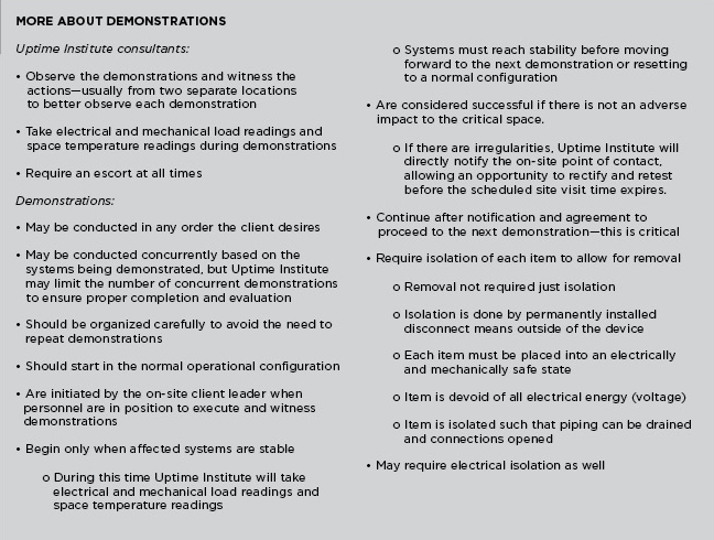
Fundamentally, the Tier Certification process is a binary exercise. The data center facility is compliant with its stated Tier objective, or it is not. So, why then, do Uptime Institute consultants sometimes experience a sinking feeling upon arriving at a site and meeting the team?
Frequently, within the first moments at the facility, it is obvious to the Uptime Institute consultant that nothing is as it should be and the next several days are going to be difficult ones.
Uptime Institute consultants can often tell at first glance whether the client has met the guidance to prepare for the Tier Certification. In fact, the consultants will often know a great deal from the number and tone of questions regarding the demonstrations list.
“You can usually tell if the client has gone through the demonstration list,” said Uptime Institute Consultant Eric Maddison. “I prepare the demonstration list from schematics, so they are not listed in order. It is the client’s obligation to sequence them logically. So it is a good sign if the client has sequenced the demonstrations logically and prepared a program with timing and other information on how they are to perform the demonstration.”
Similarly, Uptime Institute consultants can see whether technicians and appropriate load banks are available. “You can walk into a data hall and see how the load banks are positioned and get a pretty good sense for whether there will be a problem or not,” Brown said, “If the facility has a 1,200-kilowatt load and they only have two large load banks, that’s a dead giveaway that the load banks are too large and not in the right place.”
Similarly, a few quick conversations will tell whether a client has arranged appropriate staffing for the demonstrations. The facility tour provides plenty of opportunity to observe whether the staff on site is knowledgeable about the facility and has practiced the demonstrations. The appropriate level of staff varies from site to site with the complexity of the data center. But, the client needs to have people on site who understand the overall design and can operate each individual piece of equipment as well as respond to unexpected failures or performance issues.
“We start with an in-brief meeting the morning of the first day for every Tier Certification and that usually takes about an hour, and then we do a tour of the facility, which can take anywhere from 2-4 hours, depending on the size of the facility. By the time those are finished, we have a pretty good idea of whether they are in the A, B, C, or D range of preparation. You start to worry if no one can answer the questions you pose, or if they don’t really have a plan or schedule for demonstrations. You can also get a good comfortable feeling if everybody has the answers, and they know where the equipment is and how it works.”
During this first day, the consultants will also determine who the client liaison is, meet the whole client team, and go over the goals of the program and site visit. During the site tour, the consultants will familiarize themselves with the facility, verify it looks as expected, check that valves and breakers are in place, and confirm equipment nameplates.
Having the proper team on site requires a certain amount of planning. Brown said that owners often inadvertently cause a big challenge by letting contractors and vendors go before the site visit. “They’ve done the construction, they’ve done the operations, and they’ve done the commissioning,” he said, “But then the Operations team comes in cold on Monday after everyone else has left. The whole brain trust that knows how the facility systems work and operate just left the site. And there’s a stack of books and binders 2-feet long for the Operations guys to read, good luck.”
Brown described a much better scenario in which the Uptime Institute consultants arrive on site and find, “The Operations team ready to go and the processes and procedures are already written. They are ready to take over on Day 1 and remain in place for 20 years. They can roll through the demonstrations. And they have multiple team members checking each other, just like they were doing maintenance for 5 years together.
“During the demonstrations, they are double checking process and procedures. ‘Oh wait,’ they’ll say, ‘we need to do this.’ They will update the procedure and do the demonstration again. In this case, the site is going to be ready to handover and start working the Monday after we leave. And everybody’s there still trying to finish up that last little bit of understanding the data center, and see that the process and procedures have all the information they need to effectively operate for years to come.”
In these instances, the owner would have positioned the Operations staff in place early in the project, whether that role is filled by a vendor or in-house staff.
In one case, a large insurer staffed a new facility by transferring half the staff from an existing data center and hiring the rest. That way, it had a mix of people who knew the company’s systems and knew how things worked. They were also part of the commissioning process. The experienced people could then train the new hires.
During the demonstration, the team will interrupt the incoming utility power supply and see that the UPS carries the critical load until the engine generators come on line and provide power to the data center and that the cooling system maintains the critical load during the transition.
WHAT CAUSES POOR PERFORMANCE DURING TIER CERTIFICATION?
So with all these opportunities to prepare, why do some Tier Certifications become difficult experiences?
Obviously, lack of preparation tops the list. Brown said, “Often, there’s hubris. ‘I am a savvy owner, and therefore, the construction team knows what they are doing, and they’ll get it right the first time.’” Similarly, clients do not always understand that the Tier Certification is not a rubber stamp. Maddison recalled more than one instance when he arrived on site only to find the site unprepared to actually perform any of the demonstrations.
Failure to understand the isolation requirements, incomplete drawings, design changes made after the Design Certification, and incomplete or abbreviated commissioning can cause headaches too. Achieving complete isolation of equipment, in particular, has proven to be challenging for some owners.
Sometimes clients aren’t familiar with all the features of a product, but more often the client will open the breakers and think it is isolated. Similar situations can arise when closing valves to confirm that a chilled water system is Concurrently Maintainable or Fault Tolerant.
Incomplete or changed drawings are a key source of frustration. Brown recalled one instance when the Tier Certified Design Documents did not show a generator control. And, since each and every system must meet the Tier requirement, the “new” equipment posed a dilemma, as no demonstration had been devised.
More common, though, are changes to design drawings. Brown said, “During every construction there are going to be changes from what’s designed to what’s built; sometimes there are Tier implications. And, these are not always communicated to us, so we discover them on the site visit.”
Poor commissioning will also cause site visit problems. Brown said, “A common view is that commissioning is turning everything on to see if it works. They’ll say, ‘Well we killed the utility power and the generator started. We have some load in there.’ They just don’t understand that load banking only the generator isn’t commissioning.”
He cites an instance in which the chillers weren’t provided the expected cooling. It turned out that cooling tubes were getting clogged by dirt and silt. “There’s no way they did commissioning—proper commissioning—or they would have noticed that.”
Construction delays can compromise commissioning. As Brown said, “Clients expect to have a building handed over on a certain date. Of course there are delays in construction, delays in commissioning, and delays because equipment didn’t work properly when it was first brought in. For any number of reasons the schedule can be pushed. And the commissioning just gets reduced in scope to meet that same schedule.”
Very often, then, the result is that owner finds that the Tier Certification cannot be completed because not everything has been tested thoroughly and things are not working as anticipated.
If the commissioning is compromised or the staff is not prepared, can the facility pass the Tier Certification anyway?
The short answer is yes.
But often these problems are indications of deeper issues that indicate a facility may not meet the performance requirements of the owner, require expensive mechanical and electrical changes, or cause move-in dates to be postponed–or some combination of all three. In these instances, failing the Tier Certification at the specified and expected time may be the least of the owner’s worries.
In these instances and many others, Uptime Institute consultants can—and do—offer useful advice and solutions. Communication is the key because each circumstance is different. In some cases, the solutions, including multiple site visits, can be expensive. In other cases, however, something like a delayed client move-in date can be worked out by rescheduling a site visit.
In addition, Maddison points out the well-prepared clients can manage the expected setbacks that might occur during the site visit. “Often more compartmentalization is needed or more control strategy. Some clients work miracles. They move control panels or put in new breakers overnight.”
But, successful outcomes like that must be planned. Asking questions, preparing Operations teams, scheduling and budgeting for Commissioning, and understanding the value of the Tier Certification can lead to a smooth process and a facility that meets or exceeds client requirements.
The aftermath of a smooth site visit should almost be anticlimactic. Uptime Institute consultants will prepare a Tier Certification Memorandum documenting any remaining issues, listing any documents to be updated, and describing the need for possible follow-on site visits.
And then finally, upon successful completion of the process, the owner receives the Tier Certification of Constructed Facility letter, an electronic foil, and plaque attesting to the performance of the facility.
Uptime Institute’s Chris Brown, Eric Maddison, and Ryan Orr contributed to this article.
Moscow State University Meets HPC Demands
/in Design/by Kevin HeslinHPC supercomputing and traditional enterprise IT facilities operate very differently
By Andrey Brechalov
In recent years, the need to solve complex problems in science, education, and industry, including the fields of meteorology, ecology, mining, engineering, and others, has added to the demand for high-performance computing (HPC). The result is the rapid development of HPC systems, or supercomputers, as they are sometimes called. The trend shows no signs of slowing, as the application of supercomputers is constantly expanding. Research today requires ever more detailed modeling of complex physical and chemical processes, global atmospheric phenomena, and distributed systems behavior in dynamic environments. Supercomputer modeling provides fine results in these areas and others, with relatively low costs.
Supercomputer performance can be described in petaflops (pflops), with modern systems operating at tens of pflops. However, performance improvements cannot be achieved solely by increasing the number of existing computing nodes in a system, due to weight, size, power, and cost considerations. As a result, designers of supercomputers attempt to improve their performance by optimizing their architecture and components, including interconnection technologies (networks) and by developing and incorporating new types of computing nodes having greater computational density per unit of area. These higher-density nodes require the use of new (or well-forgotten old) and highly efficient methods of removing heat. All this has a direct impact on the requirements for site engineering infrastructure.
HPC DATA CENTERS
Supercomputers can be described as a collection of interlinked components and assemblies—specialized servers, network switches, storage devices, and links between the system and the outside world. All this equipment can be placed in standard or custom racks, which require conditions of power, climate, security, etc., to function properly—just like the server-based IT equipment found in more conventional facilities.
Low- or medium-performance supercomputers can usually be placed in general purpose data centers and even in server rooms, as they have infrastructure requirements similar to other IT equipment, except for a bit higher power density. There are even supercomputers for workgroups that can be placed directly in an office or lab. In most cases, however, any data center designed to accommodate high power density zones should be able to host one of these supercomputers.
On the other hand, powerful supercomputers usually get placed in dedicated rooms or even buildings that include unique infrastructure optimized for a specific project. These facilities are pretty similar to general-purpose data centers. However, dedicated facilities for powerful supercomputers host a great deal of high power density equipment, packed closely together. As a result, these facilities must make use of techniques suitable for removing the higher heat loads. In addition, the composition and characteristics of IT equipment for an HPC data center are already known before the site design begins and its configuration does not change or changes only subtly during its lifetime, except for planned expansions. Thus it is possible to define the term HPC data center as a data center intended specifically for placement of a supercomputer.
Figure 1. Types of HPC data center IT equipment
The IT equipment in a HPC data center built using the currently popular cluster-based architecture can be generally divided into two types, each having its own requirements for engineering infrastructure Fault Tolerance and component redundancy (see Figure 1 and Table 1).
Table 1. Types of IT equipment located in HPC data centers
The difference in the requirements for redundancy for the two types of IT equipment is because applications running on a supercomputer usually have a reduced sensitivity to failures of computational nodes, interconnection leaf switches, and other computing equipment (see Figure 2). These differences enable HPC facilities to incorporate segmented infrastructures that meet the different needs of the two kinds of IT equipment.
Figure 2. Generic HPC data center IT equipment and engineering infrastructure.
ENGINEERING INFRASTRUCTURE FOR COMPUTATIONAL EQUIPMENT
Supercomputing computational equipment usually incorporates cutting-edge technologies and has extremely high power density. These features affect the specific requirements for engineering infrastructure. In 2009, the number of processors that were placed in one standard 42U (19-inch rack unit) cabinet at Moscow State University’s (MSU) Lomonosov Data Center was more than 380, each having a thermal design power (TDP) of 95 watts for a total of 36 kilowatts (kW/rack). Adding 29 kW/rack for auxiliary components, such as (e.g. motherboards, fans, and switches brings the total power requirement to 65 kW/rack. Since then the power density for such air-cooled equipment has reached 65 kW/rack.
On the other hand, failures of computing IT equipment do not cause the system as a whole to fail because of the cluster technology architecture of supercomputers and software features. For example, job checkpointing and automated job restart software features enable applications to isolate computing hardware failures and the computing tasks management software ensures that applications use only operational nodes even when some faulty or disabled nodes are present. Therefore, although failures in engineering infrastructure segments that serve computational IT equipment increase the time required to perform computing tasks, these failures do not lead to a catastrophic loss of data.
Supercomputing computational equipment usually operates on single or N+1 redundant power supplies, with the same level of redundancy throughout the electric circuit to the power input. In the case of a single hardware failure, segmentation of the IT loads and supporting equipment limits the effects of the failure to only a part of IT equipment.
Customers often refuse to install standby-rated engine-generator sets, completely relying on utility power. In these cases, the electrical system design is defined by the time required for normal IT equipment shutdown and the UPS system mainly rides through brief power interruptions (a few minutes) in utility power.
Cooling systems are designed to meet similar requirements. In some cases, owners will lower redundancy and increase segmentation without significant loss of operational qualities to optimize capital expense (CapEx) and operations expense (OpEx). However, the more powerful supercomputers expected in the next few years will require the use of technologies, including partial or full liquid cooling, with greater heat removal capacity.
OTHER IT EQUIPMENT
Auxiliary IT equipment in a HPC data center includes air-cooled servers (sometimes as part of blade systems), storage systems, and switches in standard 19-inch racks that only rarely reach the power density level of 20 kW/rack. Uptime Institute’s annual Data Center Survey reports that typical densities are less than 5 kW/rack.
This equipment is critical to cluster functionality; and therefore, usually has redundant power supplies (most commonly N+2) that draw power from independent sources. Whenever hardware with redundant power is applied, the rack’s automatic transfer switches (ATS) are used to ensure the power failover capabilities. The electrical infrastructure for this equipment is usually designed to be Concurrently Maintainable, except that standby-rated engine-generator sets are not always specified. The UPS system is designed to provide sufficient time and energy for normal IT equipment shutdown.
The auxiliary IT equipment must be operated in an environment cooled to 18–27°C, (64–81°F) according to ASHRAE recommendations, which means that solutions used in general data centers will be adequate to meet the heat load generated by this equipment. These solutions often meet or exceed Concurrent Maintainability or Fault Tolerant performance requirements.
ENERGY EFFICIENCY
In recent years, data center operators have put a greater priority on energy efficiency. This focus on energy saving also applies to specialized HPC data centers. Because of the numerous similarities between the types of data centers, the same methods of improving energy efficiency are used. These include the use of various combinations of free cooling modes, higher coolant and set point temperatures, economizers, evaporative systems, and variable frequency drives and pumps as well as numerous other technologies and techniques.
Reusing the energy used by servers and computing equipment is one of the most promising of these efficiency improvements. Until recent years, all that energy had been dissipated. Moreover, based on average power usage efficiency (PUE), even efficient data centers must use significant energy to dissipate the heat they generate.
Facilities that include chillers and first-generation liquid cooling systems generate “low potential heat” [coolant temperatures of 10–15°C (50–59°F), 12–17°C (54–63°F), and even 20–25°C (68–77°F)] that can be used rather than dissipated, but doing so requires significant CapEx and OpEx (e.g., use of heat pumps) that lead to long investment return times that are usually considered unacceptable.
Increasing the heat potential of the liquid coolants improves the effectiveness of this approach, absent direct expansion technologies. And even while reusing the heat load is not very feasible in server-based spaces, there have been positive applications in supercomputing computational spaces. Increasing the heat potential can create additional opportunities to use free cooling in any climate. That allows year-round free cooling in the HPC data center is a critical requirement.
A SEGMENTED HPC DATA CENTER
Earlier this year the Russian company T-Platforms deployed the Lomonosov-2 supercomputer at MSU, using the segmented infrastructure approach. T-Platforms has experience in supercomputer design and complex HPC data center construction in Russia and abroad. When T-Platforms built the first Lomonosov supercomputer, it scored 12th in the global TOP500 HPC ratings. Lomonosov-1 has been used at 100% of its capacity with about 200 tasks waiting in job queue on average. The new supercomputer will significantly expand MSU’s Supercomputing Center capabilities.
The engineering systems for the new facility were designed to support the highest supercomputer performance, combining new and proven technologies to create an energy-efficient scalable system. The engineering infrastructure for this supercomputer was completed in June 2014, and the computing equipment is being gradually added to the system, as requested by MSU. The implemented infrastructure allows system expansion with currently available A-Class computing hardware and perspective generations of IT equipment without further investments in the engineering systems.
THE COMPUTATIONAL SEGMENT
The supercomputer is based on T-Platforms’s A-class high-density computing system and makes use of a liquid cooling system (see Figure 3). A-class supercomputers support designs of virtually any scale. The peak performance of one A-class enclosure is 535 teraflops (tflops) and a system based on it can easily be extended up to more than 100 pflops. For example, the combined performance of the five A-class systems already deployed at MSU reached 2,576 tflops in 2014 (22nd in the November 2014 TOP500) and was about 2,675 tflops in July 2015. This is approximately 50% greater than the peak performance of the entire first Lomonosov supercomputer (1,700 tflops, 58th in the same TOP500 edition). A supercomputer made of about 100 A-class enclosures would perform on par with the Tianhe-2 (Milky Way-2) system at National Supercomputer Center in Guangzhou (China) that leads the current TOP500 list at about 55 pflops.
Figure 3. The supercomputer is based on T-Platforms’s A-class high-density computing system and makes use of a liquid cooling system
All A-class subsystems, including computing and service nodes, switches, and cooling and power supply equipment, are tightly integrated in a single enclosure as modules with hot swap support (including those with hydraulic connections). The direct liquid cooling system is the key feature of the HPC data center infrastructure. It almost completely eliminates air as the medium of heat exchange. This solution improves the energy efficiency of the entire complex by making these features possible:
• IT equipment installed in the enclosure has no fans
• Heat from the high-efficiency air-cooled power supply units (PSU) is removed using water/air heat exchangers embedded in the enclosure
• Electronic components in the cabinet do not require computer room air for cooling
• Heat dissipated to the computer room is minimized because the cabinet is sealed and insulated
• Coolant is supplied to the cabinet at cabinet at 44°C (111°F) with up to 50°C (122°F) outbound under full load, which enables year-round free cooling at ambient summer temperatures of up to 35°C (95°F) and the use of dry coolers without adiabatic systems (see Figure 4)
Figure 4. Coolant is supplied to the auxiliary IT cabinets at 44°C (50°C outbound under full load), which enables year-round free cooling at ambient summer temperatures of up to 35°C and the use of dry coolers without adiabatic systems
In addition noise levels are also low because liquid cooling eliminates powerful node fans that generate noise in air-cooled systems. The only remaining fans in A-Class systems are embedded in the PSUs inside the cabinets, and these fans are rather quiet. Cabinet design contains most of the noise from this source.
INFRASTRUCTURE SUPPORT
The power and cooling systems for Lomonosov-2 follow the general segmentation guidelines. In addition, they must meet the demands of the facility’s IT equipment and engineering systems at full load, which includes up to 64 A-class systems (peak performance over 34 pflops) and up to 80 auxiliary equipment U racks in 42U, 48U, and custom cabinets. At full capacity these systems require 12,000-kW peak electric power capacity.
Utility power is provided by eight 20/0.4-kV substations, each having two redundant power transformers making a total of 16 low-voltage power lines with a power limit of 875 kW/line in normal operation.
Although no backup engine-generator sets have been provisioned, at least 28% of the computing equipment and 100% of auxiliary IT equipment is protected by UPS providing at least 10 minutes of battery life for all connected equipment.
The engineering infrastructure also includes two independent cooling systems: a warm-water, dry-cooler type for the computational equipment and a cold-water, chiller system for auxiliary equipment. These systems are designed for normal operation in temperatures ranging from -35 to+35°C (-31 to +95°F) with year-round free cooling for the computing hardware. The facility also contains an emergency cooling system for auxiliary IT equipment.
The facility’s first floor includes four 480-square-meters (m2) rooms for computing equipment (17.3 kW/m2) and four 280-m2 rooms for auxiliary equipment (3 kW/m2) with 2,700 m2 for site engineering rooms on an underground level.
POWER DISTRIBUTION
The power distribution system is built on standard switchboard equipment and is based on the typical topology for general data centers. In this facility, however, the main function of the UPS is to ride through brief blackouts of the utility power supply for select computing equipment (2,340 kW), all auxiliary IT equipment (510 kW), and engineering equipment systems (1,410 kW). In the case of a longer blackout, the system supplies power for proper shutdown of connected IT equipment.
The UPS system is divided into three independent subsystems. The first is for computing equipment, the second is for auxiliary equipment, and the third is for engineering systems. In fact, the UPS system is deeply segmented because of the large number of input power lines. This minimizes the impact of failures of engineering equipment on supercomputer performance in general.
The segmentation principle is also applied to the physical location of the power supply equipment. Batteries are placed in three separate rooms. In addition, there are three UPS rooms and one switchboard room for the computing equipment that is unprotected by UPS. Figure 5 shows one UPS-battery room pair.
Figure 5. A typical pair of UPS-battery rooms
Three, independent, parallel UPS, each featuring N+1 redundancy (see Figure 6), feed the protected computing equipment. This redundancy, along with bypass availability and segmentation, simplifies UPS maintenance and the task of localizing a failure. Considering that each UPS can receive power from two mutually redundant transformers, the overall reliability of the system meets the owner’s requirements.
Figure 6. Power supply plan for computing equipment
Three independent parallel UPS systems are also used for the auxiliary IT equipment because it requires greater failover capabilities. The topology incorporates a distributed redundancy scheme that was developed in the late 1990s. The topology is based on use of three or more UPS modules with independent input and output feeders (see Figure 7).
Figure 7. Power supply for auxiliary equipment
This system is more economical than a 2N-redundant configuration while providing the same reliability and availability levels. Cable lines connect each parallel UPS to the auxiliary equipment computer rooms. Thus, the computer room has three UPS-protected switchboards. The IT equipment in these rooms, being mostly dual fed, is divided into three groups, each of which is powered by two switchboards. Single-feed and N+1 devices are connected through a local rack-level ATS (see Figure 8).
Figure 8. Single-feed and N+1-redundant devices are connected through a local rack-level ATS
ENGINEERING EQUIPMENT
Some of the engineering infrastructure also requires uninterrupted power in order to provide the required Fault Tolerance. The third UPS system meets this requirement. It consists of five completely independent single UPSs. Technological redundancy is fundamental. Redundancy is applied not to the power lines and switchboard equipment but directly to the engineering infrastructure devices.
The number of UPSs in the group (Figure 9 shows three of five) determines the maximum redundancy to be 4+1. This system can also provide 3+2 and 2N configurations). Most of the protected equipment is at N+1 (see Figure 9).
Figure 9. Power supply for engineering equipment
In general, this architecture allows decommissioning of any power supply or cooling unit, power line, switchboard, UPS, etc., without affecting the serviced IT equipment. Simultaneous duplication of power supply and cooling system components is not necessary.
OVERALL COOLING SYSTEM
Lomonosov-2 makes use of a cooling system that consists of two independent segments, each of which is designed for its own type of IT equipment (see Table 2). Both segments make use of a two-loop scheme with plate heat exchangers between loops. The outer loops have a 40% ethylene-glycol mixture that is used for coolant. Water is used in the inner loops. Both segments have N+1 components (N+2 for dry coolers in the supercomputing segment).
Table 2. Lomonosov makes use of a cooling system that consists of two independent segments, each of which is designed to meet the different requirements of the supercomputing and auxiliary IT equipment.
This system, designed to serve the 64 A-class enclosures, has been designated the hot-water segment. Its almost completely eliminates the heat from extremely energy-intensive equipment without chillers (see Figure 10). Dry coolers dissipate all the heat that is generated by the supercomputing equipment up to ambient temperatures of 35°C (95°F). Power is required only for the circulation pumps of both loops, dry cooler fans, and automation systems.
Figure 10. The diagram shows the cooling system’s hot water segment.
Under full load and in the most adverse conditions, the instant PUE would be expected to be about 1.16 for the fully deployed system of 64 A-class racks (see Figure 11).
Figure 11. Under full load and under the most adverse conditions, the instant PUE (power utilization efficiency would be expected to be about 1.16 for the fully deployed system of 64 A-class racks)
The water in the inner loop has been purified and contains corrosion inhibitors. It is supplied to computer rooms that will contain only liquid-cooled computer enclosures. Since the enclosures do not use computer room air for cooling, the temperature in these rooms is set at 30°C (86°F) and can be raised to 40°C (104°F) without any influence on the equipment performance. The inner loop piping is made of PVC/CPVC (polyvinyl chloride/chlorinated polyvinyl chloride) thus avoiding electrochemical corrosion.
COOLING AUXILIARY IT EQUIPMENT
It is difficult to avoid using air-cooled IT equipment, even in a HPC project, so MSU deployed a separate cold-water [12–17°C (54–63°F)] cooling system. The cooling topology in these four spaces is almost identical to the hot-water segment deployed in the A-class rooms, except that chillers are used to dissipate the excess heat from the auxiliary IT spaces to the atmosphere. In the white spaces, temperatures are maintained using isolated Hot Aisles and in-row cooling units. Instant PUE for this isolated system is about 1.80, which is not a particularly efficient system (see Figure 12).
Figure 12. In white spaces, temperatures are maintained using isolated hot aisles and in-row cooling units.
If necessary, some of the capacity of this segment can be used to cool the air in the A-class computing rooms. The capacity of the cooling system in these spaces can meet up to 10% of the total heat inflow in each of the A-class enclosures. Although sealed, they still heat the computer room air through convection. But in fact, passive heat radiation from A-class enclosures is less than 5% of the total power consumed by them.
EMERGENCY COOLING
An emergency-cooling mode exists to deal with utility power input blackouts, when both cooling segments are operating on power from the UPS. In emergency mode, each cooling segment has its own requirements. As all units in the first segment (both pump groups, dry coolers, and automation) are connected to the UPS, the system continues to function until the batteries discharge completely.
In the second segment, the UPS services only the inner cooling loop pumps, air conditioners in computer rooms, and automation equipment. The chillers and outer loop pumps are switched off during the blackout.
Since the spaces allocated for cooling equipment are limited, it was impossible to use a more traditional method of stocking cold water at the outlet of the heat exchangers (see Figure 13). Instead, the second segment of the emergency system features accumulator tanks with water stored at a lower temperature than in the loop [about 5°C (41°F) with 12°C (54°F) in the loop] to keep system parameters within a predetermined range. Thus, the required tank volume was reduced to 24 cubic meters (m3) instead of 75 m3, which allowed the equipment to fit in the allocated area. A special three-way valve allows mixing of chilled water from the tanks into the loop if necessary. Separate small low-capacity chillers (two 55-kW chillers) are responsible for charging the tanks with cold water. The system charges the cold-water tanks in about the time it takes to charge the UPS batteries.
Figure 13. Cold accumulators are used to keep system parameters within a predetermined range.
MSU estimates that segmented cooling with a high-temperature direct water cooling segment reduces its total cost of ownership by 30% compared to data center cooling architectures based on direct expansion (DX) technologies. MSU believes that this project shows that combining the most advanced and classical technologies and system optimization allows significant savings on CapEx and OpEx while keeping the prerequisite performance, failover, reliability and availability levels.
Andrey Brechalov
Andrey Brechalov is Chief Infrastructure Solutions Engineer of T-Platforms, a provider of high performance computing (HPC) systems, services, and solutions headquartered in Moscow, Russia. Mr. Brechalov has responsibility for building engineering infrastructures for supercomputers SKIF K-1000, SKIF Cyberia, and MSU Lomonosov-2 as well as smaller supercomputers by T-Platforms. He has worked for more than 20 years in computer industry including over 12 years in HPC and specializes in designing, building, and running supercomputer centers.