Data Center Facility Owners See Modules as Efficient Way to Deploy Capital
Compass sets the course with new modular data center approach.
The term modular has been used to describe a variety of approaches to data center design. Historically, the first commercially available modular design was a 2007 Sun Microsystems container-based product called the Black Box. Today, the term describes products that range from shipping containers and simple repeated designs to fully manufactured IT spaces and MEP systems built in factories and shipped to various sites.
Many modular data center providers have written white papers that tout the benefits of their proprietary designs, but there are also some informative reports on the ins and outs of modular design. John Stanley of 451 Research presented the results of his survey work at the Uptime Institute Symposium in May 2012. He surveyed 35 companies that use and provide various types of modular solutions for data centers. His research pointed out that 65% of those surveyed deployed capacity in ‘chunky’ increments, specifically highlighting the need for small chunks of capacity per module or deployment to match growth of their data centers.
Compass has based its business strategy on this industry driver and five main features of modular design:
- High quality
- Low construction costs
- Speed to deploy
- Integrated supply chain
- Low operating costs
In the Green Grid paper, “Deploying and Using Containerized/Modular Data Center Facilities,” published in November 2011, the Green Grid demonstrated that modular data centers can follow capacity requirements more closely, freeing capital and keeping MEP systems more fully loaded than large-scale deployments. The authors of the paper showed that end users could employ their utility systems and floor spaces more fully, without undue concern for system exhaustion or space starvation. The authors discuss how small increments of capacity can follow compute demands more closely, with the caveat that the facility must also have a faster implementation cycle in order to match the changing IT requirements.
The data center industry is beginning to realize the benefits of the early industrial revolution. Standardized modular power center designs provide some of the same benefits to design and construction personnel. Instead of hand-building custom electrical systems for each data center, the modular approach allows for greater deployment speed, improved quality and lower costs, all achieved by using factory-based labor. The use of modules also relieves labor stacking on the job site, while reducing the overall cost of the work by a significant amount.
In his 1936 paper, Factors Affecting the Cost of Airplanes, T.P. Wright first quantified the cost savings that could be attained using factory labor. Wright showed that the direct labor cost of assembling an airframe decreased by roughly 20% for each doubling of the production numbers. In other words, if the labor cost of building one airframe was $1,000,000, the labor cost of building two of the same models might be $800,000 each. Doubling again would mean the cost of four the same airframes would be $640,000 each, or 36% lower than the first unique model.
Compass Data Centers intended to take advantage of this principle as it developed its patent-pending solution. In doing so, Compass has found that modular designs enable it to:
- Benefit from learning-curve dynamics to improve quality and speed of implementation with each iteration
- Lower operating costs from design efficiencies that tune initial innovative ideas
- Provide predictable reliability attributes and repeatable, low-cost operations
- Deliver a standard product
As a result, Compass has moved from building a prototype on every data center project to productizing the data center program and build.
Despite the fact that the industry has not settled on a clear definition of the ‘modular data center,’ it is attempting to evade this ambiguity by proclaiming the coming of ‘Version 2,’ which seems to include prefabrication as a fundamental element. Before, modular construction was associated with ISO containers and packaged chillers. Now, modularity is being embraced as synonymous with sound design and sound capital usage.
The Compass Deployment
Every data center design begins with the establishment of availability and power requirements – reliability and power density are the cornerstones of any data center specification. The business needs of the enterprise and the IT applications to be contained within the data center should drive these decisions.
Virtually every initial design addresses the project power requirements and references the Uptime Institute’s well-known Tier specifications to define reliability requirements. Uptime’s Tier Standard helps define the equipment and systems required to support the reliability and power demands of the business’s IT model. If the needs of a business are truly defined by an Uptime Tier III specification, then its data center design should be certifiable as a Tier III design.
Compass’ Truly Modular Architecture design provides for standard features such as RHI Modular Power Solutions’ Modular Power Center units, which are also built off-site, power modules that can be configured to provide a 2N power infrastructure, and N+1 mechanical systems. Other Compass architecture features include:
- 10,000 square feet of column-free raised floor space
- Hardened structure (Seismic 1.5 and Category 4 Hurricane Winds)
- The capability to support up to 20-kW racks
- Convenient operations, staging and storage spaces
- Uptime Tier III-certifiable design
- Uptime Tier III-certifiable facility
The standardized design of the Compass Modular Architecture provides assurance that the facility will be Tier III design certified. Internal auditors and external customers can not only be assured of the design certification, but also have the option to certify the facility itself. Importantly, the ability to productize a unique modular data center solution into a repeatable and well-defined process was a top priority. Modularizing data center components permits control over three primary variables:
- Cost
- Quality
- Schedule
Compass shares the view that these three variables are the only three points that end users actually care about. Compass also believes that modularity:
- Is cost effective
- Is not always a prefabricated solution
- Increases quality
- Supports continuous improvement
- May bring jurisdictional issues
Some jurisdictions have misconceptions about modular or containerized solutions. They envision standard ISO shipping containers, assembled on-site, as the basis of the construction process.
Meeting the local authority having jurisdiction (AHJ) early in the project’s developmental cycle is an effective way to establish trust and dispel misconceptions. Providing an extensive amount of specific information on the modular components of the proposed data centers is a good way to start.
Next Phase
As part of its schematic designs, Compass decided that its basic architectural scheme would be a shell that would contain a 10,000-square-foot (ft2) column-free, raised-floor hall and all the traditional support spaces. Compass made this decision based on the collective experience of its internal and consultant teams, as well as market analysis.
Compass decided that the systems, called Modular Power Centers (MPCs), would be packaged and delivered as standardized systems. This work was provided by Modular Power Solutions. The MPCs could be installed either internally or externally to the data center’s brick-and-mortar shell structure. Crosby and the MPC executives have filed for patent protection of the intellectual property.
Compass chose not to employ a central mechanical plant, but rather to deploy an N+1 redundant rooftop mechanical system to support the facility’s HVAC requirements. So, the schematic design established the following parameters:
Data Hall:
- 10,000 ft2 data hall
- Column free
- 36-inch raised-floor white space, supporting up to 500 racks
- 120 watts per square foot , with the ability to cool heterogeneous loads and accommodate racks up to 30 kW
- Hardened for wind and seismic conditions
- N+1 rooftop mechanical units
- Tier III-certifiable
Support Spaces:
- Office area, breakroom, loading dock, security station, engineering office, storage room, staging area, PPOP Room, fire riser room, restroom and janitorial.
Modular Power Centers:
- 1.2-MW Modular Power Centers, which could be either internally or externally installed at the facility.
The basis-of-design (BOD) goals are then used for the next step in the design process, the creation of a single-line diagram. The development of the schematic design (SD) phase single-line diagram brings together the conceptual components and requirements of the BOD (see Figure 1).
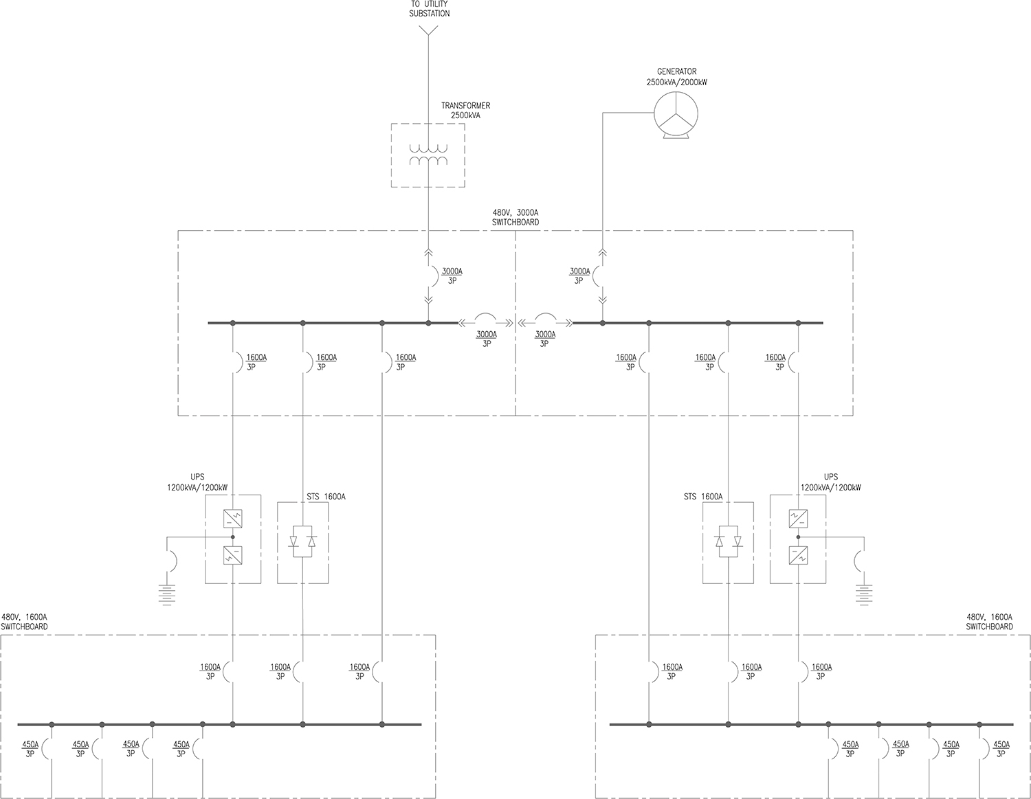
Figure 1. Schematic design single-line diagram
The initial single-line is the tool that Compass used to determine the structure and components required for the electrical distribution system. The MPCs must be sized to be able to support the demands of the 1.2-MW data hall, the mechanical systems and the support spaces. The single-line diagram is also used to validate the Tier III redundancy and concurrent maintainability requirements. The redundancy of critical components and systems and the requirement for de-energized maintenance must be worked through at this stage of the design process.
The major electrical distribution system components were identified as:
- One 2500-kilovolt-ampere (kVA) utility transformer
- One 2500-kVA/2000-kW standby-rated generator
- One redundant 2500-kVA/2000-kW standby generator
- One 480-volts (V), 3000-amp (A) main distribution switchboard
- Two 1200-kW high-efficiency uninterruptible power supplies (UPS)
- Two 1600-A static transfer switch (STS) bypasses
- Two 1600-A UPS output distribution switchboards
- Two 1600-A maintenance bypasses
The Compass one-line based on the Tier III requirements provided a look at the electrical system’s redundancy (see Figure 2).
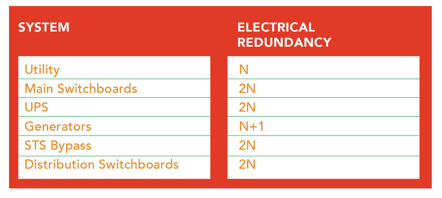
Figure 2. Electrical system redundancy
Then Compass added two isolation or tie breakers to the main switchboard in order to meet the Tier III concurrently maintainable requirement. These breakers were required to allow either side of the switchboard to be shut down and completely de-energized for service. The tie breakers can also be used to enhance fault tolerance. If they are forced to trip before the main circuit breakers on either side, the non-faulted side of the system can remain operational.
The decision was made to look to the local utility provider to supply an N redundant 2500-kVA utility power transformer. The 2500-kVA/2000-kW standby generator in the base system is N redundant. A second N+1 or 2N redundant generator added to the lineup meets the Tier III redundancy requirements. The second generator will be connected to the opposite side of the switchboard lineup. Compass preferred generator redundancy over utility redundancy, finding generators to be more reliable than the utility, based upon its experience that blackouts tend to regional in nature (as seen with hurricane Sandy).
The remaining equipment would be installed in a Power Center module. That equipment was identified as:
- Two 480-V, 3000-A main distribution switchboards
- Two 1200-kW high-efficiency UPS units
- Two 1600-A STS bypasses
- Two 1600-A UPS output distribution switchboards
- Two 1600-A maintenance bypasses
Based on the equipment defined in the single-line, Compass determined that at least two MPCs would be required.
The tie breakers provide a natural point to split the system. This split became the basis of how the system is packaged. And the size of the modules and weight of the MPCs is constrained by the need to ship them over highways from the assembly facility to the job site. Typically, those shipping packages are not to exceed 50 feet by 12 feet and 100,000 pounds.
Each MPC switchboard lineup features a 3000-A and a 1600-A UL 891-listed switchboard. Each switchboard is equipped with two 3000-A, four 400-A, and four 450-A UL 489-listed circuit breakers. All circuit breakers larger than 200-A are 100% duty rated. All circuit breakers feature zone selective interlocks (ZSIs). A ZSI ties the circuit breaker trip units together, allowing them to communicate in order to ensure that the circuit breaker closest to the fault trips first. Increasing the fault isolation capabilities increases the data center’s ability to maintain operational continuity.
The main switchboards are configured as main-tie-main-tie-main. Each CPC has a dedicated programmable logic controller (PLC). The PLCs are hot swappable, meaning that if either processor goes down, the other processor will automatically take control. The I/O rack is located in the A CPC. There is no power bussing in the I/O section. The switchgear can be manually operated if the I/O rack is de-energized for maintenance.
Modbus Protocol is provided to the Schneider Electric StruXureWare management system at the PLC gateway for each main switchboard. The main switchgear has integrated revenue-grade power-quality metering.
Each side of the redundant power system features a 1.2-MW Schneider Electric APC Symmetra Megawatt UPS (see Figure 3). Each UPS has a dedicated external 1600-A continuous-duty-rated static bypass switch. Power to the two UPS systems is delivered from two separate (A/B) switchboards. Each switchboard is able to support the entire data center. The two tie breakers operate in the normally closed position.
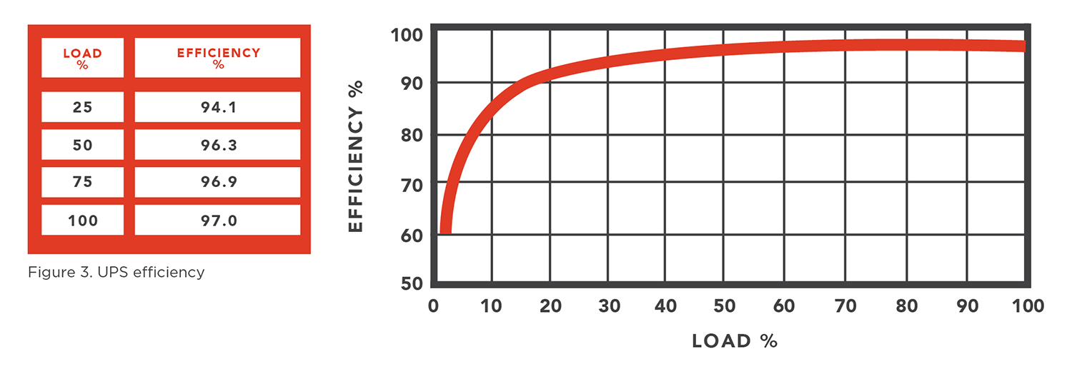
Figure 3. UPS efficiency
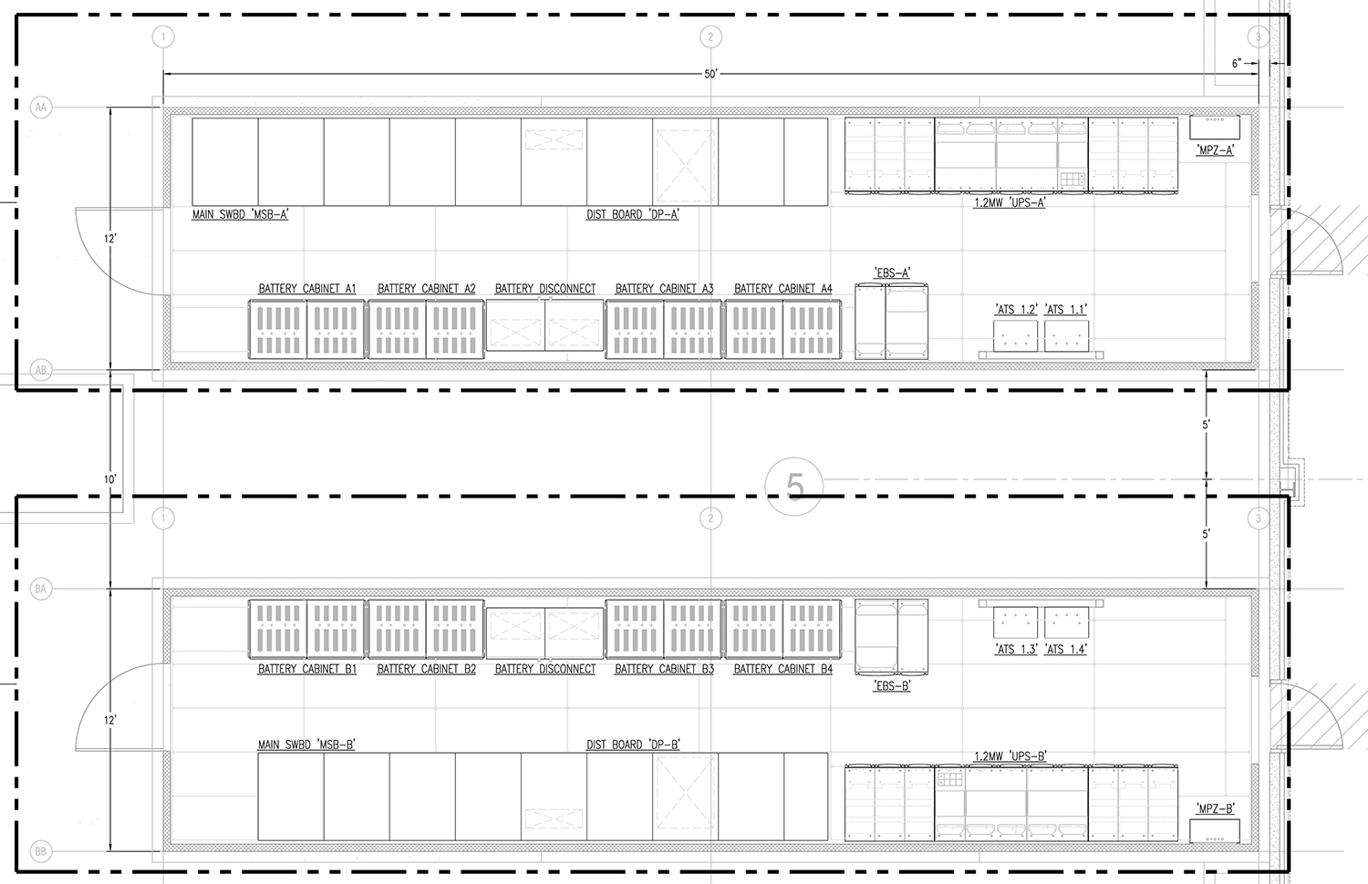
Figure 4. (Above) Modular Power Center – top view (patent pending)
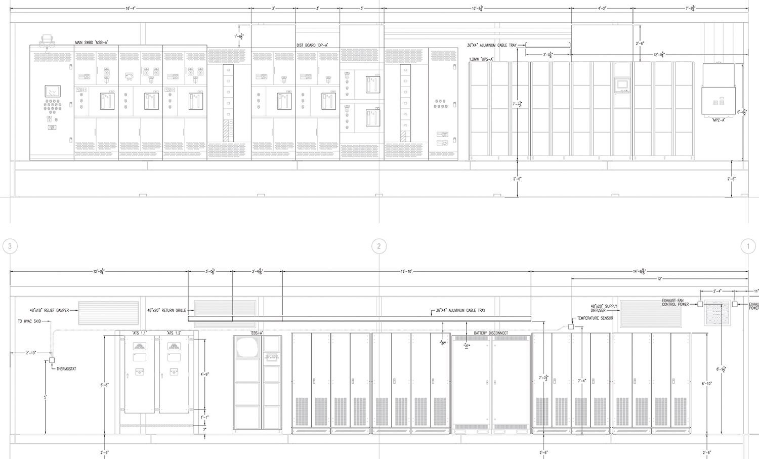
Figure 5. (Below) Modular Power Center – plan view (patent pending)
Power for the data hall will be derived from two identical MPC modules, each of which is factory-assembled prior to on-site delivery. The first layouts were completed for the MPCs with the addition of the following components:
- Four battery cabinets per side for 5-minutes battery backup at 1.2 MW
- Two automatic transfer switches for N+1 rooftop units
- One 208/120-V distribution panel for local power needs
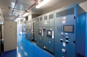
Figure 6. Modular Power
Center – interior
The MPCs (see Figures 4-8) are IBC-rated R17 structures, which meet Miami-Dade County 149-mph wind-pressure loading requirements. The MPCs are constructed to provide protection with respect to harmful effects on the equipment due to the ingress of water (rain, sleet, snow), and will be undamaged by the external formation of ice on the enclosure or seismic events.
Compass employs 2.0-MW/2.5-MVA, 277/480-V, 3ø, four-wire generator rated at 1825 kW to provide standby power (see Figure 9 and 10).
Compass determined that the data center infrastructure will require support from a 2.0-MW/2.5-MVA generator. The sequence of operation of the total system is controlled automatically through deployment of redundant PLC control units installed in each of the 3000-A main switchboards. Should the primary standby generator fail to come online after loss of the utility source, the swing generator will pick up the critical loads of the system. Each generator will be provided with a weather-protective enclosure. All generator permits (including all operations, fuel storage, noise and air) will be obtained and maintained with the appropriate AHJ. Generators are equipped with 4,000-gallon fuel storage belly tanks for 24 hours of fuel capacity at full load.
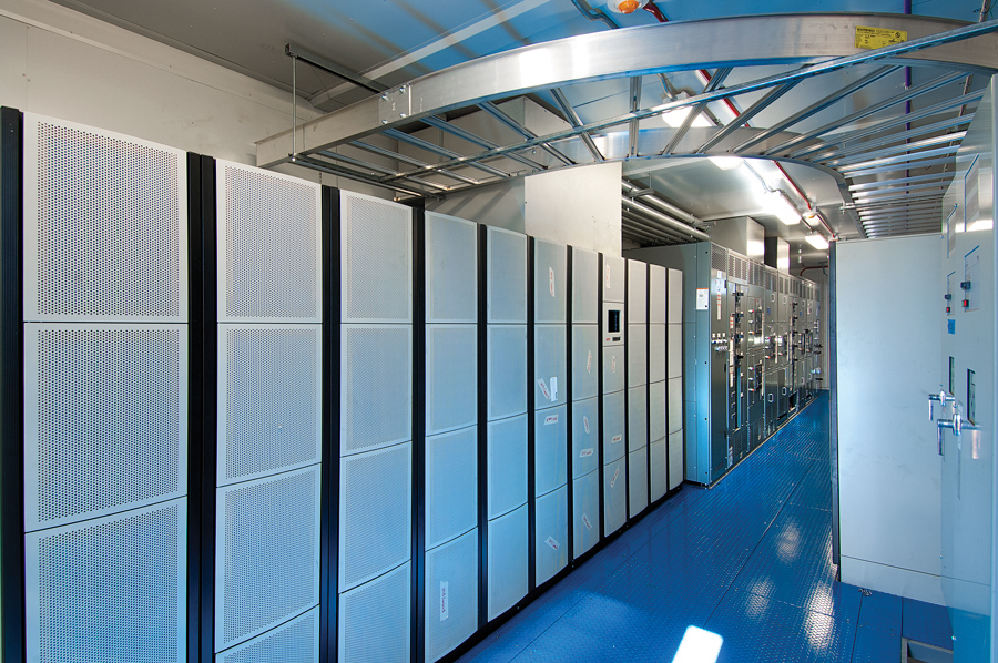
Figure 7. Modular Power Center – interior
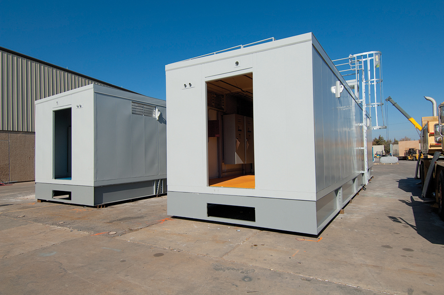
Figure 8. Modular Power Center – exterior
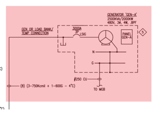
Figure 9. Standby generator
The output of each UPS module is a 1600-A distribution board equipped with a maintenance bypass. A solenoid key release unit (SKRU) is provided to ensure that the UPS has transferred to bypass before the MBP breaker can be engaged to the output switchboard. This will always be a closed transition transfer so that critical load power will never be lost.
Critical power to the IT load will be provided by eight 300-kVA PDUs installed in an alternating A/B arrangement in the data hall to provide 208/120-V power to either overhead busway or remote power panels. Each PDU has a 300-kVA K-13 rated transformer and six 225-A breakers. Additionally, each PDU has six integrated revenue-grade power-monitoring meters.
Compass determined that the mechanical requirements for each data hall can be supported by four 120-ton rooftop units (RTUs). The four RTUs provide N+1 system redundancy. Power for each RTU will be available from either the A or B System through dedicated automatic transfer switches (see Figure 11). The units feature integrated controls allowing for efficient airside economization across all units. A proprietary rapid-restart feature ensures full air movement within 30 seconds after restoration of power. The system controls deliver uniform under-floor pressures.
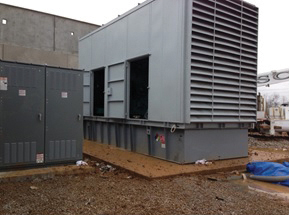
Figure 10. Generator exterior
This single-line diagram (see Figure 12) represents the next step in the construction document’s development process: the design development (DD)-phase documents. The updated single-line features significant developments in the design process. The new features are:
The division of the electrical distribution system into two completely separate MPCs
- The second generator was added to provide N+1 redundancy
- Provisions for ‘A side’ and ‘B side’ mechanical feeders
- The integration of the main and output switchboards
- The integration of the maintenance bypass (MBP) breaker into the new contiguous switchboard lineup
- The introduction of dual-programmable logic controllers (PLCs)
- The introduction of a remote main utility circuit breaker
The new single-line diagram now reflects the separate MPCs. The MPCs in this arrangement actually complement each other, providing 2N redundancy to the data hall.
A second generator was added to provide 2N generator redundancy. In the future, this second generator could be shared with additional data halls on the same campus. The redundancy of the generators would then be N+1.
Each MPC was outfitted with provisions to provide power for the entire mechanical system. Normally, power for one-half of the mechanical equipment is supplied by each MPC. Dedicated ATSs will automatically roll power to any active MPC if power were lost.
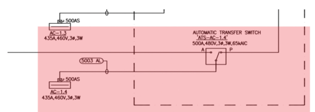
Figure 11. Power for each RTU is available from dedicated automatic transfer switches.
The new single-line shows how both the input and output switchboards have been integrated into a single switchgear lineup. The new lineup provided for a simplified interconnection scheme when it was installed in the MPC.
The use of dual MPC facilitates the use of dual PLCs. The ability of the PLCs to stay in synchronous operation allows for a seamless transfer of control between either unit.
High levels of arc-flash energy in the main switchboards became a concern when the decision was made to have the utility provide the main 2500-kVA transformer and the transformer’s primary-side protection. Most utilities design their protection schemes to protect the utility’s own equipment. This typically doesn’t translate into limiting the arc-flash energy levels on the secondary side of these large transformers. Remoting the main utility breaker outside the MPC allows the arc-flash energy to be contained outside the remote switchboard. The arc-flash energy inside the MPC is now be significantly reduced.
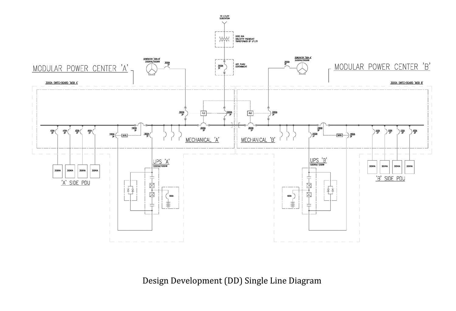
Figure 12. Design-Development (DD) single-line diagram (patent pending)
The deployment of the MPCs is just part of the modular concept that was developed for Compass Data Centers. Compass has done further development of the concept. This work and Tier III compliance with the Uptime Institute are important elements of its business plan to control costs and provide alignment of data center facilities with customers’ business requirements.
 Steve Emert earned a BSEE Degree in Electrical Engineering from San Jose State University. He is currently a Registered Professional Engineer in more than 15 states, and is director of Mission-Critical Engineering at Rosendin Electric, the largest privately owned electrical contractor in the U.S. Mr. Emert began his career performing design and analysis of industrial, commercial and utility power systems, cogeneration plant design and coordination studies. In the mid-1990s, he worked at the Ames Research Center located at Moffett Field, CA, where he began a mission-critical-focused career working on the NAS supercomputer and many of the technically advanced NASA facilities.
Since joining Rosendin Electric, Mr. Emert has provided the engineering foundation for the company’s design-build mission-critical construction business. Today Rosendin Electric is the largest design-build electrical contractor for mission-critical facilities in the U.S. Mr. Emert is an active member of the IEEE P1584 IEEE Guidelines for Performing Arc-Flash Hazard Calculations Working Group. He is a member of the IEEE P1584 Configuration Task Group, currently engaged in the process of defining a new set of standards for the next issue of the P1584 Guideline publication. Mr. Emert has coauthored IEEE EMC Society presentations and written articles on electrical power systems for Electrical Contractor Magazine.


 UI 2021

