Raytheon integrates corporate sustainability to achieve savings and recognition
By Brian J. Moore
With a history of innovation spanning 92 years, Raytheon Company provides state-of-the-art electronics, mission systems integration, and other capabilities in the areas of sensing, effects, command, control, communications, and intelligence systems, as well as a broad range of mission support services in defense, civil government, and cybersecurity markets throughout the world (see Figure 1). Raytheon employs some of the world’s leading rocket scientists and more than 30,000 engineers and technologists, including over 2,000 employees focused on IT.
Figure 1. Among Raytheon’s many national defense-oriented product and solutions are sensors, radar, and other data collection systems that can be deployed as part of global analysis and aviation.
Not surprisingly, Raytheon depends a great deal on information technology (IT) as an essential enabler of its operations and as an important component of many of its products and services. Raytheon also operates a number of data centers, which support internal operations and the company’s products and services, which make up the bulk of Raytheon’s enterprise operations.
In 2010, Raytheon established an enterprise-wide IT sustainability program that gained the support of senior leadership. The program increased the company’s IT energy efficiency, which generated cost savings, contributed to the company’s sustainability goals, and enhanced the company’s reputation. Raytheon believes that its success demonstrates that IT sustainability makes sense even in companies in which IT is important, but not the central focus. Raytheon, after all, is a product and services company like many enterprises and not a hyper scale Internet company. As a result, the story of how Raytheon came to develop and then execute its IT sustainability strategy should be relevant to companies in a wide range of industries and having a variety of business models (see Figure 2).
Figure 2. Raytheon’s enterprise-wide sustainability program includes IT and its IT Sustainability Program and gives them both visibility at the company’s most senior levels.
Over the last five years the program has reduced IT power by more than 3 megawatts (MW), including 530 kilowatts (kW) in 2015. The program has also generated over US$33 million in annual cost savings, and developed processes to ensure the 100% eco-responsible management of e-waste (see Figure 3). In addition IT has developed strong working relationships related to energy management with Facilities and other functions; their combined efforts are achieving company-level sustainability goals, and IT sustainability has become an important element of the company’s culture.
Figure 3. Each year, IT sustainability efforts build upon successes of previous years. By 2015, Raytheon had identified and achieved almost 3 megawatts of IT savings.
THE IT SUSTAINABILITY OFFICE
Raytheon is proud to be among the first companies to recognize the importance of environmental sustainability, with U.S. Environmental Protection Agency (EPA) recognitions dating back to the early 1980s.
As a result, Raytheon’s IT groups across the company employed numerous people who were interested in energy savings. On their own, they began to apply techniques such as virtualization and optimizing data center airflows to save energy. Soon after its founding, Raytheon’s IT Sustainability (initially Green IT) Office, began aggregating the results of the company’s efficiencies. As a result, Raytheon saw the cumulative impact of these individual efforts and supported the Office’s efforts to do even more work.
The IT Sustainability Office coordinates a core team with representatives from the IT organizations of each of the company’s business units and a few members from Facilities. The IT Sustainability Office has a formal reporting relationship with Raytheon’s Sustainability Steering Team and connectivity with peers in other functions. Its first order of business was to develop a strategic approach to IT sustainability. The IT Sustainability Office adopted the classic military model in which developing strategy means defining the initiative’s ends, ways, and means.
Raytheon chartered the IT Sustainability Office to:
• Develop a strategic approach that defines the program’s ends, ways, and means
• Coordinate IT sustainability efforts across the lines of business and regions of the company
• Facilitate knowledge sharing and drive adoption of best practices
• Ensure alignment with senior leadership and establish and maintain connections with sustainability efforts in other functions
• Capture and communicate metrics and other results
COMMUNICATING ACROSS BUSINESS FUNCTIONS
IT energy savings tend to pay for themselves (see Figure 4), but even so, getting a persistent, comprehensive effort to achieve energy savings requires establishing a strong understanding of why energy savings are important and communicating it company wide. A strong why is needed to overcome barriers common to most organizations:
• Everyone is busy and must deal with competing priorities. Front-line data center personnel have no end of problems to resolve or improvements they would like to make, and executives know they can only focus on a limited number of goals.
• Working together across businesses and functions requires getting people out of their day-to-day rhythms and taking time to understand and be understood by others. It also requires giving up some preferred approaches for the sake of a common approach that will have the benefit of scale and integration.
• Perserverence in the face of inevitable set backs requires a deep sense of purpose and a North Star to guide continued efforts.
Figure 4. Raytheon believes that sustainability programs tend to pay for themselves, as in this hypothetical in which adjusting floor tiles and fans improved energy efficiency with no capital expenditure.
The IT Sustainability Office’s first steps were to define the ends of its efforts and to understand how its work could support larger company goals. The Sustainability Office quickly discovered that Raytheon had a very mature energy program with annual goals that its efforts would directly support. The Sustainability Office also learned about the company’s longstanding environmental sustainability program, which the EPA’s Climate Leaders program regularly recognized for its greenhouse gas reductions. The Sustainability Office’s work would support company goals in this area as well. Members of the IT Sustainability Office also learned about the positive connection between sustainability and other company objectives, including growth, employee engagement, increased innovation, and improved employee recruiting and retention.
As the full picture came into focus, the IT Sustainability Office came to understand that IT energy efficiency could have a big effect on the company’s bottom line. Consolidating a server would not only save energy by eliminating its power draw but also by reducing cooling requirements and eliminating lease charges, operational labor charges, and data center space requirements. IT staff realized that their virtualization and consolidation efforts could help Raytheon avoid building a new data center and also that their use of simple airflow optimization techniques had made it possible to avoid investments in new cooling capacity.
Having established the program’s why, the IT Sustainability Office began to define the what. It established three strategic intents:
• Operate IT as sustainably as possible
• Partner with other functions to create sustainability across the company
• Build a culture of sustainability
Of the three, the primary focus has been operating IT more sustainably. In 2010, Raytheon set 15 public sustainability goals to be accomplished by 2015. Raytheon’s Board of Directors regularly reviewed progress towards these goals. Of these, IT owned two:
1. Generate 1 MW of power savings in data centers
2. Ensure that 100% of all electronic waste is managed eco-responsibly.
IT met both of these goals and far exceeded its 1 MW power savings goal, generating just over 3 MW of power savings during this period. In addition, IT contributed to achieving several of the other company-wide goals. For example, reductions in IT power helped the company meet its goal of reducing greenhouse gas emissions. But the company’s use of IT systems also helped in less obvious ways, such as supporting efforts to manage the company’s use of substances of concern and conflict minerals in its processes and products.
This level of executive commitment became a great tool for gaining attention across the company. As IT began to achieve success with energy reductions, the IT Sustainability Office also began to establish clear tie-ins with more tactical goals, such as enabling the business to avoid building more data centers by increasing efficiencies and freeing up real estate by consolidating data centers.
The plan to partner with other functions grew from the realization that Facilities could help IT with data center energy use because a rapidly growing set of sensing, database, and analytics technologies presented a great opportunity to increase efficiencies across all of the company’s operations. Building a culture of sustainability in IT and across the company ensured that sustainability gains would increase dramatically as more employees became aware of the goals and contributed to reaching them. The IT Sustainability Office soon realized that being part of the sustainability program would be a significant motivator and source of job satisfaction for many employees.
Raytheon set new public goals for 2020. Instead of having its own energy goals, IT, Facilities, and others will work to reduce energy use by 10% more and greenhouse gas emissions an additional 12%. The company also wants to utilize 5% renewable energy. However, IT will however continue to own two public goals:
1. Deploy advanced energy management at 100% of the enterprise data centers
2. Deploy a next-generation collaboration environment across the company
THE MEANS
To execute projects such as airflow managements or virtualization that support broader objectives, the IT Sustainability Office makes use of commercially available technologies, Raytheon’s primary IT suppliers, and Raytheon’s cultural/structural resources. Most, if not all, these resources exist in most large enterprises.
Server and storage virtualization products provide the largest energy savings from a technology perspective. However, obtaining virtualization savings requires physical servers to host the virtual servers and storage and modern data center capacity to host the physical servers and storage devices. Successes achieved by the IT Sustainability Office encouraged the company leadership to upgrade infrastructure and the internal cloud computing environment necessary to support the energy-saving consolidation efforts.
The IT Sustainability Office also made use of standard data center airflow management tools such as blanking panels and worked with Facilities to deploy wireless airflow and temperature monitoring to eliminate hotspots without investing in more equipment.
In addition to hardware and software, the IT Sustainability Office leveraged the expertise of Raytheon’s IT suppliers. For example, Raytheon’s primary network supplier provided on-site consulting to help safely increase the temperature set points in network gear rooms. In addition, Raytheon is currently leveraging the expertise of its data center service provider to incorporate advanced server energy management analytics into the company’s environments.
Like all companies, Raytheon also has cultural and organizational assets that are specific to it, including:
• Governance structures that include the sustainability governance model and operating structures with IT facilitate coordination across business groups and the central IT function.
• Raytheon’s Global Communications and Advance Media Services organizations provide professional expertise for getting the company’s message out both internally and externally.
• The cultural values embedded in Raytheon’s vision, “One global team creating trusted, innovative solutions to make the world a safer place,” enable the IT Sustainability Office to get enthusiastic support from anywhere in the company when it needs it.
• An internal social media platform has enabled the IT Sustainability Office to create the “Raytheon Sustainability Community” that has nearly 1,000 self-subscribed members who discuss issues ranging from suggestions for site-specific improvements, to company strategy, to the application of solar power in their homes.
• Raytheon Six Sigma is “our disciplined, knowledge-based approach designed to increase productivity, grow the business, enhance customer satisfaction, and build a customer culture that embraces all of these goals.” Because nearly all the company’s employees have achieved one or more levels of qualification in Six Sigma, Raytheon can quickly form teams to address newly identified opportunities to reduce energy-related waste.
Raytheon’s culture of sustainability pays dividends in multiple ways. The engagement of staff outside of the IT infrastructure and operations function directly benefits IT sustainability goals. For example it is now common for non-IT engineers who work on programs supporting external customers to reach back to IT to help ensure that best practices are implemented for data center design or operation. In addition, other employees use the company’s internal social media platform to get help in establishing power settings or other appropriate means to put the computers in an energy savings mode when they notice wasteful energy use.The Facilities staff has also become very conscious of energy use in computer rooms and data closets and now know how to reach out when they notice a facility that seems to be over-cooled or otherwise running inefficiently. Finally employees now take the initiative to ensure that end-of-life electronics and consumables such as toner or batteries are disposed of properly.
There are also benefits beyond IT energy use. For many employees, the chance to engage with the company’s sustainability program and interact with like-minded individuals across the company is a major plus in their job satisfaction and sense of pride in working for the company. Human Resources values this result so much that it highlight’s Raytheon’s sustainability programs and culture in its recruiting efforts.
Running a sustainability program like this, over time also requires close attention to governance. In addition to having a cross-company IT Sustainability Office, Raytheon formally includes sustainability at each of the three levels of the company sustainability governance model (see Figure 5). A council with membership drawn from senior company leadership provides overall direction and maintains the connection; a steering team comprising functional vice-presidents meets quarterly to track progress, set goals, and make occasional course corrections; and the working team level is where the IT Sustainability Office connects with peer functions and company leadership. This enterprise governance model initially grew out of an early partnership between IT and Facilities that had been formed to address data center energy issues.
Figure 5. Raytheon includes sustainability in each of its three levels of governance.
Reaching out across the enterprise, the IT Sustainability Office includes representatives from each business unit who meet regularly to share knowledge, capture and report metrics, and work common issues. This structure enabled Raytheon to build a company-wide community of practice, which enabled it to sustain progress over multiple years and across the entire enterprise.
At first, the IT Sustainability Office included key contacts within each line of business who formed a working team that established and reported metrics, identified and shared best practices, and championed the program within their business. Later, facility engineers and more IT staff would be added to the working team, so that it became the basis for a larger community of practice that would meet occasionally to discuss particular topics or engage a broader group in a project. Guest speakers and the company’s internal social media platform are used to maintain the vitality of this team.
As a result of this evolution, the IT Sustainability Office eventually established partnership relationships with Facilities; Environment, Health and Safety; Supply Chain; Human Resources; and Communications at both the corporate and business levels. These partnerships enabled Raytheon to build energy and virtualization reviews into its formal software development methodology. This makes the software more likely to run in an energy-efficient manner and also easier for internal and external customers to use the software in a virtualized environment.
THE WAYS
The fundamental ways of reducing IT energy use are well known:
• Virtualizing servers and storage allows individual systems to support multiple applications or images, making greater use of the full capabilities of the IT equipment and executing more workloads in less space with less energy
• Identifying and decommissioning servers that are not performing useful work has immediate benefits that become significant when aggregated
• Optimizing airflows, temperature set points, and other aspects of data center facility operations often have very quick paybacks
• Data center consolidation, moving from more, older, less-efficient facilities to fewer, higher efficiency data centers typically reduces energy use and operating costs while also increasing reliability and business resilience
After establishing the ends and the ways, the next step was getting started. Raytheon’s IT Sustainability Office found that establishing goals that aligned with those of leadership was a way to establish credibility at all levels across the company, which was critical to developing initial momentum. Setting targets, however, was not enough to maintain this credibility. The IT Sustainability Office found it necessary to persistently apply best practices at scale across multiple sectors of the company. As a result, IT Sustainability Office devised means to measure, track, and report progress against the goals. The metrics had to be meaningful and realistic, but also practical.
In some cases, measuring energy savings is a straightforward task. When facility engineers are engaged in enhancing the power and cooling efficiency of a single data center, their analyses typically include a fairly precise estimate of expected power savings. In most cases the scale of the work will justify installing meters to gather the needed data. It is also possible to do a precise engineering analysis of the energy savings that come from rehosting a major enterprise resource planning (ERP) environment or a large storage array.
On the other hand, it is much harder to get a precise measurement for each physical server that is eliminated or virtualized at enterprise scale. Though it is generally easy to get power usage for any one server, it is usually not cost effective to measure and capture this information for hundreds or thousands of servers having varying configurations and diverse workloads, especially when the servers operate in data centers of varying configurations and efficiencies.
The IT Sustainability Office instead developed a standard energy savings factor that could be used to provide a valid estimate of power savings when applied to the number of servers taken out of operation. To establish the factor, the IT Sustainability Office did a one-time study of the most common servers in the company’s Facilities and developed a conservative consensus on the net energy savings that result from replacing them with a virtual server.
The factor multiplies an average net plug savings of 300 watts (W) by a Power Usage Effectiveness (PUE) of 2.0, which was both an industry average at that time and a decent estimate of the average across Raytheon’s portfolio of data centers. Though in many cases actual plug power savings exceed 300 W, having a conservative number that could be easily applied allowed for effective metric collection and for communicating the value being achieved. The team also developed a similar factor for cost savings, which took into account hardware lease expense and annual operating costs. These factors, while not precise, were conservative and sufficient to report tens of millions of dollars in cost savings to senior management, and were used thoughout the five-year long pursuit of the company’s 2015 sustainability goal. To reflect current technology and environmental factors, these energy and cost savings factors are being updated in conjunction with setting new goals.
EXTERNAL RECOGNITION
The IT Sustainability Office also saw that external recognition helps build and maintain momentum for the sustainability program. For example, in 2015 Raytheon won a Brill Award for Energy Efficiency from Uptime Institute. In previous years, Raytheon received awards from Computerworld, InfoWorld, Homeland Security Today, and e-stewards. In addition, Raytheon’s CIO appeared on a CNBC People and Planet feature and was recognized by Forrester and ICEX for creating an industry benchmark.
Internal stakeholders, including senior leadership, noted this recognition. The awards increased their awareness of the program and how it was reducing costs, supporting company sustainability goals, and contributing to building the company’s brand. When Raytheon’s CEO mentioned the program and the two awards it won that year at a recent annual shareholders meeting, the program instantly gained credibility.
In addition to IT-specific awards, the IT Sustainability Office’s efforts to partner led it to support company-level efforts to gain recognition for the company’s other sustainability efforts, including providing content each year for Raytheon’s Corporate Responsibility Report and for its application for the EPA Climate Partnership Award. This partnership strategy leads the team to work closely with other functions on internal communications and training efforts.
For instance, the IT Sustainability Office developed one of the six modules in the company’s Sustainability Star program, which recognizes employee efforts and familiarizes them with company sustainability initiatives. The team also regularly provides content for intranet-based news stories, supports campaigns related to Earth Day and Raytheon’s Energy Month, and hosts the Raytheon Sustainabilty Community.
Brian J. Moore
Brian J. Moore is senior principal information systems technologist in the Raytheon Company’s Information Technology (IT) organization in Global Business Services. The Raytheon Company, with 2015 sales of $23 billion and 61,000 employees worldwide, is a technology and innovation leader specializing in defense, security, and civil markets throughout the world. Raytheon is headquartered in Waltham, MA. The Raytheon IT Sustainability Office, which Moore leads, focuses on making IT operations as sustainable as possible, partnering with other functions to leverage IT to make their business processes more sustainable, and creating a culture of sustainability. Since he initiated this program in 2008, it has won six industry awards, including, most recently, the 2015 Brill Award for IT Energy Efficiency from Uptime Institute. Moore was also instrumental in creating Raytheon’s sustainability governance model and in setting the company’s public sustainability goals.
How insights from Tier Certification of Constructed Facilities avoids unforeseen costs and errors for all new projects
By Kevin Heslin
Uptime Institute’s Tier Classification System has been a part of the data center industry lexicon for 20 years. Since its creation in the mid-1990s, the system has evolved into the global standard for third-party validation of data center critical infrastructure. At the same time, misconceptions about the Tier program confuse the industry and make it harder for a data center team to understand and prepare sufficiently for the rigors of the Tier process. Fortunately, Uptime Institute provides guidance and plenty of opportunity for clients to prepare for a Tier Certification well before the on-site review of functionality demonstrations.
This article discusses the Tier Certification process in more detail, specifically explaining the on-site demonstration portion of a Tier Certification. This is a highly rigorous process that requires preparation.
Uptime Institute consultants notice that poor preparation for a Tier Certification of Constructed Facility signals that serious problems will be uncovered during the facility demonstration. Resolving problems at this late stage may require a second site visit or even expensive mechanical and electrical changes. These delays may also cause move-in dates to be postponed. In other situations, the facility may not qualify for the Certification at the specified and expected design load.
TIER CERTIFICATION–HOW IT WORKS
Tier Certification is a performance-based evaluation of a data center’s specific infrastructure and not a checklist or cookbook. The process ensures that the owner’s facility has been constructed as designed and verifies that it is capable of meeting the defined availability requirements. Even the best laid plans can go awry, and common construction phase practices or value engineering proposals can compromise the design intent of a data center (See “Avoiding Data Center Construction Problems” by Keith Klesner, The Uptime Institute Journal, vol 5, p. 6).
The site visit provides an opportunity to observe whether the staff is knowledgeable about the facility and has practiced the demonstrations.
With multiple vendors, subcontractors, and typically more than 50 different disciplines involved in any data center project—structural, electrical, HVAC, plumbing, fuel pumps, networking, and more—it would be remarkable if there were no errors or unintended risks introduced during the construction process.
The Tier Certification typically starts with a company deploying new data center capacity. The data center owner defines a business requirement to achieve a specific Tier (I-IV) level to ensure the asset meets performance capacity, effectiveness, and reliability requirements. Only Uptime Institute can certify that a data center design and/or constructed facility does, in fact, meet the owner’s Tier objective.
The first step is the Tier Certification of Design Documents. Uptime Institute consultants review 100% of the design documents, ensuring that each and every electrical, mechanical, monitoring, and automation subsystem meets the Tier objective requirements. Uptime Institute reports its findings to the owner, noting any Tier deficiencies. It is then up to the owner’s team to revise the drawings to address those deficiencies.
After Uptime Institute consultants determine that the revised design drawings correct the deficiencies, the Tier Certification of Design Documents foil may be awarded.
Immediately after the Design Certification is awarded, the Facility Certification begins when Uptime Institute consultants begin devising a list of demonstrations to be performed by site staff upon the conclusion of Level 5 Commissioning. Uptime Institute consultants provide the demonstrations to the client in advance and are available to answer questions throughout the construction process. In addition, Uptime Institute has created an instructional presentation for each Tier Level, so that owners can better understand the process and how to prepare for the site visit.
Fortunately, Uptime Institute provides guidance and plenty of opportunity for clients to prepare for a Facility Certification well before the on-site review of functionality demonstrations. Uptime Institute Senior Vice President, Tier Standards, Chris Brown said, “From my perspective a successful Facility Certification is one in which the clients are well prepared and all systems meet Tier requirements the first time. They have all their documents and planning done. And, pretty much everything goes without a hitch.”
Planning for the Facility Certification begins early in the construction process. Clients must schedule adequate time for Level 5 Commissioning and the site visit, ensuring that construction delays and cost overruns do not compromise time for either the commissioning or Certification process. They will also want to make sure that vendors and contractors will have the right personnel on site during the Certification visit.
Tier Certification of Constructed Facility:
• Ensures that a facility has been constructed as designed
• Verifies a facility’s capability to meet the defined availability requirements
• Follows multiple mechanical and electrical criteria as defined in the Tier Standard: Topology
• Seamlessly integrates into the project schedule
• Ensures that deficiencies in the design are identified, solved, and tested before operations commence
• Includes live system demonstrations under real-world conditions, validating performance according to the
facility’s Tier objective
• Conducts demonstrations specifically tailored to the exact topology of the data center
A team of Uptime Institute consultants will visit the site for 3-5 days, generally a little more than a month after construction of critical systems ends, allowing plenty of time for commissioning. While on site, the team identifies discrepancies between the design drawings and installed equipment. They also observe the results of each demonstration.
PREPARATIONS FOR TIER CERTIFICATION DEMONSTRATIONS
The value of Tier Certification comes from finding and eliminating blind spots, points of failure, and weak points before a site is fully operational and downtime results.
In an ideal scenario, data center facilities teams would have successfully completed Level 5 Commissioning (Integrated System Testing). The commissioning testing would have already exercised all of the components as though the data center were operational. That means that load banks simulating IT equipment are installed in the data center to fully test the power and cooling. The systems are operated together to ensure that the data center operates as designed in all specified maintenance and failure scenarios.
Everything should be running exactly as specified, and changes from the design should be minimal and insignificant. In fact, facility personnel should be familiar with the facility and its operation and may even have practiced the demonstrations during commissioning.
“Clients who are prepared have fully commissioned the site and they have put together the MOPs and SOPs (operating procedures) for the work that is required to actually accomplish the demonstrations,” said Chris Brown, Uptime Institute Senior Vice President, Tier Standards. “They have the appropriate technical staff on site. And, they have practiced or rehearsed the demonstrations before we get there.
“Because we typically come in for site visit immediately following Level 5 Commissioning, we ask for a commissioning schedule, and that will give us an indication of how rigorous commissioning has been and give us an idea of whether this is going to be a successful facility certification or not.”
Once on site, Uptime Institute consultants observe the Operations team as it performs the different demonstrations, such as interrupting the incoming utility power supply to see that the UPS carries the critical load until the engine generators come on line and provide power to the data center and that the cooling system maintains the critical load during the transition.
Integrated systems testing requires load banks to simulate live IT equipment to test how the data center power and cooling systems perform under operating conditions.
Other demonstrations include removing redundant capacity components from service and showing that, for example, N engine generators can support the data center critical load or that the redundant chilled water distribution loop can be removed from service while still sufficiently cooling the data center.
“Some of these demonstrations take time, especially those involving the cooling systems,” Brown said.
The client must prepare properly because executing the demonstrations in a timely manner requires that the client:
1. Create a schedule and order of demonstrations
2. Create all procedures required to complete the functionality demonstrations
3. Provide necessary technical support personnel
a. Technicians
b. Installers
c. Vendors
4. Provide, install, and operate load banks
5. Direct on-site technical personnel
6. Provide means to measure the presence of voltage on electrical devices during isolation by qualified personnel.
Even though the assessment evaluates the physical topology and equipment, organizations need proper staffing, training, and documentation in place to ensure the demonstrations are performed successfully.
AVOID TIER CERTIFICATION HORROR STORIES
Fundamentally, the Tier Certification process is a binary exercise. The data center facility is compliant with its stated Tier objective, or it is not. So, why then, do Uptime Institute consultants sometimes experience a sinking feeling upon arriving at a site and meeting the team?
Frequently, within the first moments at the facility, it is obvious to the Uptime Institute consultant that nothing is as it should be and the next several days are going to be difficult ones.
Uptime Institute consultants can often tell at first glance whether the client has met the guidance to prepare for the Tier Certification. In fact, the consultants will often know a great deal from the number and tone of questions regarding the demonstrations list.
“You can usually tell if the client has gone through the demonstration list,” said Uptime Institute Consultant Eric Maddison. “I prepare the demonstration list from schematics, so they are not listed in order. It is the client’s obligation to sequence them logically. So it is a good sign if the client has sequenced the demonstrations logically and prepared a program with timing and other information on how they are to perform the demonstration.”
Similarly, Uptime Institute consultants can see whether technicians and appropriate load banks are available. “You can walk into a data hall and see how the load banks are positioned and get a pretty good sense for whether there will be a problem or not,” Brown said, “If the facility has a 1,200-kilowatt load and they only have two large load banks, that’s a dead giveaway that the load banks are too large and not in the right place.”
Similarly, a few quick conversations will tell whether a client has arranged appropriate staffing for the demonstrations. The facility tour provides plenty of opportunity to observe whether the staff on site is knowledgeable about the facility and has practiced the demonstrations. The appropriate level of staff varies from site to site with the complexity of the data center. But, the client needs to have people on site who understand the overall design and can operate each individual piece of equipment as well as respond to unexpected failures or performance issues.
Brown recalled one facility tour that included 25 people, but only two had any familiarity with the site. He said, “Relying on a headcount is not possible; we need to understand who the people are and their backgrounds.
“We start with an in-brief meeting the morning of the first day for every Tier Certification and that usually takes about an hour, and then we do a tour of the facility, which can take anywhere from 2-4 hours, depending on the size of the facility. By the time those are finished, we have a pretty good idea of whether they are in the A, B, C, or D range of preparation. You start to worry if no one can answer the questions you pose, or if they don’t really have a plan or schedule for demonstrations. You can also get a good comfortable feeling if everybody has the answers, and they know where the equipment is and how it works.”
During this first day, the consultants will also determine who the client liaison is, meet the whole client team, and go over the goals of the program and site visit. During the site tour, the consultants will familiarize themselves with the facility, verify it looks as expected, check that valves and breakers are in place, and confirm equipment nameplates.
Having the proper team on site requires a certain amount of planning. Brown said that owners often inadvertently cause a big challenge by letting contractors and vendors go before the site visit. “They’ve done the construction, they’ve done the operations, and they’ve done the commissioning,” he said, “But then the Operations team comes in cold on Monday after everyone else has left. The whole brain trust that knows how the facility systems work and operate just left the site. And there’s a stack of books and binders 2-feet long for the Operations guys to read, good luck.”
Brown described a much better scenario in which the Uptime Institute consultants arrive on site and find, “The Operations team ready to go and the processes and procedures are already written. They are ready to take over on Day 1 and remain in place for 20 years. They can roll through the demonstrations. And they have multiple team members checking each other, just like they were doing maintenance for 5 years together.
“During the demonstrations, they are double checking process and procedures. ‘Oh wait,’ they’ll say, ‘we need to do this.’ They will update the procedure and do the demonstration again. In this case, the site is going to be ready to handover and start working the Monday after we leave. And everybody’s there still trying to finish up that last little bit of understanding the data center, and see that the process and procedures have all the information they need to effectively operate for years to come.”
In these instances, the owner would have positioned the Operations staff in place early in the project, whether that role is filled by a vendor or in-house staff.
In one case, a large insurer staffed a new facility by transferring half the staff from an existing data center and hiring the rest. That way, it had a mix of people who knew the company’s systems and knew how things worked. They were also part of the commissioning process. The experienced people could then train the new hires.
During the demonstration, the team will interrupt the incoming utility power supply and see that the UPS carries the critical load until the engine generators come on line and provide power to the data center and that the cooling system maintains the critical load during the transition.
WHAT CAUSES POOR PERFORMANCE DURING TIER CERTIFICATION?
So with all these opportunities to prepare, why do some Tier Certifications become difficult experiences?
Obviously, lack of preparation tops the list. Brown said, “Often, there’s hubris. ‘I am a savvy owner, and therefore, the construction team knows what they are doing, and they’ll get it right the first time.’” Similarly, clients do not always understand that the Tier Certification is not a rubber stamp. Maddison recalled more than one instance when he arrived on site only to find the site unprepared to actually perform any of the demonstrations.
Failure to understand the isolation requirements, incomplete drawings, design changes made after the Design Certification, and incomplete or abbreviated commissioning can cause headaches too. Achieving complete isolation of equipment, in particular, has proven to be challenging for some owners.
Sometimes clients aren’t familiar with all the features of a product, but more often the client will open the breakers and think it is isolated. Similar situations can arise when closing valves to confirm that a chilled water system is Concurrently Maintainable or Fault Tolerant.
Incomplete or changed drawings are a key source of frustration. Brown recalled one instance when the Tier Certified Design Documents did not show a generator control. And, since each and every system must meet the Tier requirement, the “new” equipment posed a dilemma, as no demonstration had been devised.
More common, though, are changes to design drawings. Brown said, “During every construction there are going to be changes from what’s designed to what’s built; sometimes there are Tier implications. And, these are not always communicated to us, so we discover them on the site visit.”
Poor commissioning will also cause site visit problems. Brown said, “A common view is that commissioning is turning everything on to see if it works. They’ll say, ‘Well we killed the utility power and the generator started. We have some load in there.’ They just don’t understand that load banking only the generator isn’t commissioning.”
He cites an instance in which the chillers weren’t provided the expected cooling. It turned out that cooling tubes were getting clogged by dirt and silt. “There’s no way they did commissioning—proper commissioning—or they would have noticed that.”
Construction delays can compromise commissioning. As Brown said, “Clients expect to have a building handed over on a certain date. Of course there are delays in construction, delays in commissioning, and delays because equipment didn’t work properly when it was first brought in. For any number of reasons the schedule can be pushed. And the commissioning just gets reduced in scope to meet that same schedule.”
Very often, then, the result is that owner finds that the Tier Certification cannot be completed because not everything has been tested thoroughly and things are not working as anticipated.
If the commissioning is compromised or the staff is not prepared, can the facility pass the Tier Certification anyway?
The short answer is yes.
But often these problems are indications of deeper issues that indicate a facility may not meet the performance requirements of the owner, require expensive mechanical and electrical changes, or cause move-in dates to be postponed–or some combination of all three. In these instances, failing the Tier Certification at the specified and expected time may be the least of the owner’s worries.
In these instances and many others, Uptime Institute consultants can—and do—offer useful advice and solutions. Communication is the key because each circumstance is different. In some cases, the solutions, including multiple site visits, can be expensive. In other cases, however, something like a delayed client move-in date can be worked out by rescheduling a site visit.
In addition, Maddison points out the well-prepared clients can manage the expected setbacks that might occur during the site visit. “Often more compartmentalization is needed or more control strategy. Some clients work miracles. They move control panels or put in new breakers overnight.”
But, successful outcomes like that must be planned. Asking questions, preparing Operations teams, scheduling and budgeting for Commissioning, and understanding the value of the Tier Certification can lead to a smooth process and a facility that meets or exceeds client requirements.
The aftermath of a smooth site visit should almost be anticlimactic. Uptime Institute consultants will prepare a Tier Certification Memorandum documenting any remaining issues, listing any documents to be updated, and describing the need for possible follow-on site visits.
And then finally, upon successful completion of the process, the owner receives the Tier Certification of Constructed Facility letter, an electronic foil, and plaque attesting to the performance of the facility.
Uptime Institute’s Chris Brown, Eric Maddison, and Ryan Orr contributed to this article.
Kevin Heslin is Chief Editor and Director of Ancillary Projects at Uptime Institute. In these roles, he supports Uptime Institute communications and education efforts. Previously, he served as an editor at BNP Media, where he founded Mission Critical, a commercial publication dedicated to data center and backup power professionals. He also served as editor at New York Construction News and CEE and was the editor of LD+A and JIES at the IESNA. In addition, Heslin served as communications manager at the Lighting Research Center of Rensselaer Polytechnic Institute. He earned the B.A. in Journalism from Fordham University in 1981 and a B.S. in Technical Communications from Rensselaer Polytechnic Institute in 2000.
https://journal.uptimeinstitute.com/wp-content/uploads/2016/05/head.jpg4751201Kevin Heslinhttps://journal.uptimeinstitute.com/wp-content/uploads/2022/12/uptime-institute-logo-r_240x88_v2023-with-space.pngKevin Heslin2016-05-11 13:44:582016-05-11 13:53:25Avoid Failure and Delay on Capital Projects: Lessons from Tier Certification
HPC supercomputing and traditional enterprise IT facilities operate very differently
By Andrey Brechalov
In recent years, the need to solve complex problems in science, education, and industry, including the fields of meteorology, ecology, mining, engineering, and others, has added to the demand for high-performance computing (HPC). The result is the rapid development of HPC systems, or supercomputers, as they are sometimes called. The trend shows no signs of slowing, as the application of supercomputers is constantly expanding. Research today requires ever more detailed modeling of complex physical and chemical processes, global atmospheric phenomena, and distributed systems behavior in dynamic environments. Supercomputer modeling provides fine results in these areas and others, with relatively low costs.
Supercomputer performance can be described in petaflops (pflops), with modern systems operating at tens of pflops. However, performance improvements cannot be achieved solely by increasing the number of existing computing nodes in a system, due to weight, size, power, and cost considerations. As a result, designers of supercomputers attempt to improve their performance by optimizing their architecture and components, including interconnection technologies (networks) and by developing and incorporating new types of computing nodes having greater computational density per unit of area. These higher-density nodes require the use of new (or well-forgotten old) and highly efficient methods of removing heat. All this has a direct impact on the requirements for site engineering infrastructure.
HPC DATA CENTERS
Supercomputers can be described as a collection of interlinked components and assemblies—specialized servers, network switches, storage devices, and links between the system and the outside world. All this equipment can be placed in standard or custom racks, which require conditions of power, climate, security, etc., to function properly—just like the server-based IT equipment found in more conventional facilities.
Low- or medium-performance supercomputers can usually be placed in general purpose data centers and even in server rooms, as they have infrastructure requirements similar to other IT equipment, except for a bit higher power density. There are even supercomputers for workgroups that can be placed directly in an office or lab. In most cases, however, any data center designed to accommodate high power density zones should be able to host one of these supercomputers.
On the other hand, powerful supercomputers usually get placed in dedicated rooms or even buildings that include unique infrastructure optimized for a specific project. These facilities are pretty similar to general-purpose data centers. However, dedicated facilities for powerful supercomputers host a great deal of high power density equipment, packed closely together. As a result, these facilities must make use of techniques suitable for removing the higher heat loads. In addition, the composition and characteristics of IT equipment for an HPC data center are already known before the site design begins and its configuration does not change or changes only subtly during its lifetime, except for planned expansions. Thus it is possible to define the term HPC data center as a data center intended specifically for placement of a supercomputer.
Figure 1. Types of HPC data center IT equipment
The IT equipment in a HPC data center built using the currently popular cluster-based architecture can be generally divided into two types, each having its own requirements for engineering infrastructure Fault Tolerance and component redundancy (see Figure 1 and Table 1).
Table 1. Types of IT equipment located in HPC data centers
The difference in the requirements for redundancy for the two types of IT equipment is because applications running on a supercomputer usually have a reduced sensitivity to failures of computational nodes, interconnection leaf switches, and other computing equipment (see Figure 2). These differences enable HPC facilities to incorporate segmented infrastructures that meet the different needs of the two kinds of IT equipment.
Figure 2. Generic HPC data center IT equipment and engineering infrastructure.
ENGINEERING INFRASTRUCTURE FOR COMPUTATIONAL EQUIPMENT
Supercomputing computational equipment usually incorporates cutting-edge technologies and has extremely high power density. These features affect the specific requirements for engineering infrastructure. In 2009, the number of processors that were placed in one standard 42U (19-inch rack unit) cabinet at Moscow State University’s (MSU) Lomonosov Data Center was more than 380, each having a thermal design power (TDP) of 95 watts for a total of 36 kilowatts (kW/rack). Adding 29 kW/rack for auxiliary components, such as (e.g. motherboards, fans, and switches brings the total power requirement to 65 kW/rack. Since then the power density for such air-cooled equipment has reached 65 kW/rack.
On the other hand, failures of computing IT equipment do not cause the system as a whole to fail because of the cluster technology architecture of supercomputers and software features. For example, job checkpointing and automated job restart software features enable applications to isolate computing hardware failures and the computing tasks management software ensures that applications use only operational nodes even when some faulty or disabled nodes are present. Therefore, although failures in engineering infrastructure segments that serve computational IT equipment increase the time required to perform computing tasks, these failures do not lead to a catastrophic loss of data.
Supercomputing computational equipment usually operates on single or N+1 redundant power supplies, with the same level of redundancy throughout the electric circuit to the power input. In the case of a single hardware failure, segmentation of the IT loads and supporting equipment limits the effects of the failure to only a part of IT equipment.
Customers often refuse to install standby-rated engine-generator sets, completely relying on utility power. In these cases, the electrical system design is defined by the time required for normal IT equipment shutdown and the UPS system mainly rides through brief power interruptions (a few minutes) in utility power.
Cooling systems are designed to meet similar requirements. In some cases, owners will lower redundancy and increase segmentation without significant loss of operational qualities to optimize capital expense (CapEx) and operations expense (OpEx). However, the more powerful supercomputers expected in the next few years will require the use of technologies, including partial or full liquid cooling, with greater heat removal capacity.
OTHER IT EQUIPMENT
Auxiliary IT equipment in a HPC data center includes air-cooled servers (sometimes as part of blade systems), storage systems, and switches in standard 19-inch racks that only rarely reach the power density level of 20 kW/rack. Uptime Institute’s annual Data Center Survey reports that typical densities are less than 5 kW/rack.
This equipment is critical to cluster functionality; and therefore, usually has redundant power supplies (most commonly N+2) that draw power from independent sources. Whenever hardware with redundant power is applied, the rack’s automatic transfer switches (ATS) are used to ensure the power failover capabilities. The electrical infrastructure for this equipment is usually designed to be Concurrently Maintainable, except that standby-rated engine-generator sets are not always specified. The UPS system is designed to provide sufficient time and energy for normal IT equipment shutdown.
The auxiliary IT equipment must be operated in an environment cooled to 18–27°C, (64–81°F) according to ASHRAE recommendations, which means that solutions used in general data centers will be adequate to meet the heat load generated by this equipment. These solutions often meet or exceed Concurrent Maintainability or Fault Tolerant performance requirements.
ENERGY EFFICIENCY
In recent years, data center operators have put a greater priority on energy efficiency. This focus on energy saving also applies to specialized HPC data centers. Because of the numerous similarities between the types of data centers, the same methods of improving energy efficiency are used. These include the use of various combinations of free cooling modes, higher coolant and set point temperatures, economizers, evaporative systems, and variable frequency drives and pumps as well as numerous other technologies and techniques.
Reusing the energy used by servers and computing equipment is one of the most promising of these efficiency improvements. Until recent years, all that energy had been dissipated. Moreover, based on average power usage efficiency (PUE), even efficient data centers must use significant energy to dissipate the heat they generate.
Facilities that include chillers and first-generation liquid cooling systems generate “low potential heat” [coolant temperatures of 10–15°C (50–59°F), 12–17°C (54–63°F), and even 20–25°C (68–77°F)] that can be used rather than dissipated, but doing so requires significant CapEx and OpEx (e.g., use of heat pumps) that lead to long investment return times that are usually considered unacceptable.
Increasing the heat potential of the liquid coolants improves the effectiveness of this approach, absent direct expansion technologies. And even while reusing the heat load is not very feasible in server-based spaces, there have been positive applications in supercomputing computational spaces. Increasing the heat potential can create additional opportunities to use free cooling in any climate. That allows year-round free cooling in the HPC data center is a critical requirement.
A SEGMENTED HPC DATA CENTER
Earlier this year the Russian company T-Platforms deployed the Lomonosov-2 supercomputer at MSU, using the segmented infrastructure approach. T-Platforms has experience in supercomputer design and complex HPC data center construction in Russia and abroad. When T-Platforms built the first Lomonosov supercomputer, it scored 12th in the global TOP500 HPC ratings. Lomonosov-1 has been used at 100% of its capacity with about 200 tasks waiting in job queue on average. The new supercomputer will significantly expand MSU’s Supercomputing Center capabilities.
The engineering systems for the new facility were designed to support the highest supercomputer performance, combining new and proven technologies to create an energy-efficient scalable system. The engineering infrastructure for this supercomputer was completed in June 2014, and the computing equipment is being gradually added to the system, as requested by MSU. The implemented infrastructure allows system expansion with currently available A-Class computing hardware and perspective generations of IT equipment without further investments in the engineering systems.
THE COMPUTATIONAL SEGMENT
The supercomputer is based on T-Platforms’s A-class high-density computing system and makes use of a liquid cooling system (see Figure 3). A-class supercomputers support designs of virtually any scale. The peak performance of one A-class enclosure is 535 teraflops (tflops) and a system based on it can easily be extended up to more than 100 pflops. For example, the combined performance of the five A-class systems already deployed at MSU reached 2,576 tflops in 2014 (22nd in the November 2014 TOP500) and was about 2,675 tflops in July 2015. This is approximately 50% greater than the peak performance of the entire first Lomonosov supercomputer (1,700 tflops, 58th in the same TOP500 edition). A supercomputer made of about 100 A-class enclosures would perform on par with the Tianhe-2 (Milky Way-2) system at National Supercomputer Center in Guangzhou (China) that leads the current TOP500 list at about 55 pflops.
Figure 3. The supercomputer is based on T-Platforms’s A-class high-density computing system and makes use of a liquid cooling system
All A-class subsystems, including computing and service nodes, switches, and cooling and power supply equipment, are tightly integrated in a single enclosure as modules with hot swap support (including those with hydraulic connections). The direct liquid cooling system is the key feature of the HPC data center infrastructure. It almost completely eliminates air as the medium of heat exchange. This solution improves the energy efficiency of the entire complex by making these features possible:
• IT equipment installed in the enclosure has no fans
• Heat from the high-efficiency air-cooled power supply units (PSU) is removed using water/air heat exchangers embedded in the enclosure
• Electronic components in the cabinet do not require computer room air for cooling
• Heat dissipated to the computer room is minimized because the cabinet is sealed and insulated
• Coolant is supplied to the cabinet at cabinet at 44°C (111°F) with up to 50°C (122°F) outbound under full load, which enables year-round free cooling at ambient summer temperatures of up to 35°C (95°F) and the use of dry coolers without adiabatic systems (see Figure 4)
Figure 4. Coolant is supplied to the auxiliary IT cabinets at 44°C (50°C outbound under full load), which enables year-round free cooling at ambient summer temperatures of up to 35°C and the use of dry coolers without adiabatic systems
In addition noise levels are also low because liquid cooling eliminates powerful node fans that generate noise in air-cooled systems. The only remaining fans in A-Class systems are embedded in the PSUs inside the cabinets, and these fans are rather quiet. Cabinet design contains most of the noise from this source.
INFRASTRUCTURE SUPPORT
The power and cooling systems for Lomonosov-2 follow the general segmentation guidelines. In addition, they must meet the demands of the facility’s IT equipment and engineering systems at full load, which includes up to 64 A-class systems (peak performance over 34 pflops) and up to 80 auxiliary equipment U racks in 42U, 48U, and custom cabinets. At full capacity these systems require 12,000-kW peak electric power capacity.
Utility power is provided by eight 20/0.4-kV substations, each having two redundant power transformers making a total of 16 low-voltage power lines with a power limit of 875 kW/line in normal operation.
Although no backup engine-generator sets have been provisioned, at least 28% of the computing equipment and 100% of auxiliary IT equipment is protected by UPS providing at least 10 minutes of battery life for all connected equipment.
The engineering infrastructure also includes two independent cooling systems: a warm-water, dry-cooler type for the computational equipment and a cold-water, chiller system for auxiliary equipment. These systems are designed for normal operation in temperatures ranging from -35 to+35°C (-31 to +95°F) with year-round free cooling for the computing hardware. The facility also contains an emergency cooling system for auxiliary IT equipment.
The facility’s first floor includes four 480-square-meters (m2) rooms for computing equipment (17.3 kW/m2) and four 280-m2 rooms for auxiliary equipment (3 kW/m2) with 2,700 m2 for site engineering rooms on an underground level.
POWER DISTRIBUTION
The power distribution system is built on standard switchboard equipment and is based on the typical topology for general data centers. In this facility, however, the main function of the UPS is to ride through brief blackouts of the utility power supply for select computing equipment (2,340 kW), all auxiliary IT equipment (510 kW), and engineering equipment systems (1,410 kW). In the case of a longer blackout, the system supplies power for proper shutdown of connected IT equipment.
The UPS system is divided into three independent subsystems. The first is for computing equipment, the second is for auxiliary equipment, and the third is for engineering systems. In fact, the UPS system is deeply segmented because of the large number of input power lines. This minimizes the impact of failures of engineering equipment on supercomputer performance in general.
The segmentation principle is also applied to the physical location of the power supply equipment. Batteries are placed in three separate rooms. In addition, there are three UPS rooms and one switchboard room for the computing equipment that is unprotected by UPS. Figure 5 shows one UPS-battery room pair.
Figure 5. A typical pair of UPS-battery rooms
Three, independent, parallel UPS, each featuring N+1 redundancy (see Figure 6), feed the protected computing equipment. This redundancy, along with bypass availability and segmentation, simplifies UPS maintenance and the task of localizing a failure. Considering that each UPS can receive power from two mutually redundant transformers, the overall reliability of the system meets the owner’s requirements.
Figure 6. Power supply plan for computing equipment
Three independent parallel UPS systems are also used for the auxiliary IT equipment because it requires greater failover capabilities. The topology incorporates a distributed redundancy scheme that was developed in the late 1990s. The topology is based on use of three or more UPS modules with independent input and output feeders (see Figure 7).
Figure 7. Power supply for auxiliary equipment
This system is more economical than a 2N-redundant configuration while providing the same reliability and availability levels. Cable lines connect each parallel UPS to the auxiliary equipment computer rooms. Thus, the computer room has three UPS-protected switchboards. The IT equipment in these rooms, being mostly dual fed, is divided into three groups, each of which is powered by two switchboards. Single-feed and N+1 devices are connected through a local rack-level ATS (see Figure 8).
Figure 8. Single-feed and N+1-redundant devices are connected through a local rack-level ATS
ENGINEERING EQUIPMENT
Some of the engineering infrastructure also requires uninterrupted power in order to provide the required Fault Tolerance. The third UPS system meets this requirement. It consists of five completely independent single UPSs. Technological redundancy is fundamental. Redundancy is applied not to the power lines and switchboard equipment but directly to the engineering infrastructure devices.
The number of UPSs in the group (Figure 9 shows three of five) determines the maximum redundancy to be 4+1. This system can also provide 3+2 and 2N configurations). Most of the protected equipment is at N+1 (see Figure 9).
Figure 9. Power supply for engineering equipment
In general, this architecture allows decommissioning of any power supply or cooling unit, power line, switchboard, UPS, etc., without affecting the serviced IT equipment. Simultaneous duplication of power supply and cooling system components is not necessary.
OVERALL COOLING SYSTEM
Lomonosov-2 makes use of a cooling system that consists of two independent segments, each of which is designed for its own type of IT equipment (see Table 2). Both segments make use of a two-loop scheme with plate heat exchangers between loops. The outer loops have a 40% ethylene-glycol mixture that is used for coolant. Water is used in the inner loops. Both segments have N+1 components (N+2 for dry coolers in the supercomputing segment).
Table 2. Lomonosov makes use of a cooling system that consists of two independent segments, each of which is designed to meet the different requirements of the supercomputing and auxiliary IT equipment.
This system, designed to serve the 64 A-class enclosures, has been designated the hot-water segment. Its almost completely eliminates the heat from extremely energy-intensive equipment without chillers (see Figure 10). Dry coolers dissipate all the heat that is generated by the supercomputing equipment up to ambient temperatures of 35°C (95°F). Power is required only for the circulation pumps of both loops, dry cooler fans, and automation systems.
Figure 10. The diagram shows the cooling system’s hot water segment.
Under full load and in the most adverse conditions, the instant PUE would be expected to be about 1.16 for the fully deployed system of 64 A-class racks (see Figure 11).
Figure 11. Under full load and under the most adverse conditions, the instant PUE (power utilization efficiency would be expected to be about 1.16 for the fully deployed system of 64 A-class racks)
The water in the inner loop has been purified and contains corrosion inhibitors. It is supplied to computer rooms that will contain only liquid-cooled computer enclosures. Since the enclosures do not use computer room air for cooling, the temperature in these rooms is set at 30°C (86°F) and can be raised to 40°C (104°F) without any influence on the equipment performance. The inner loop piping is made of PVC/CPVC (polyvinyl chloride/chlorinated polyvinyl chloride) thus avoiding electrochemical corrosion.
COOLING AUXILIARY IT EQUIPMENT
It is difficult to avoid using air-cooled IT equipment, even in a HPC project, so MSU deployed a separate cold-water [12–17°C (54–63°F)] cooling system. The cooling topology in these four spaces is almost identical to the hot-water segment deployed in the A-class rooms, except that chillers are used to dissipate the excess heat from the auxiliary IT spaces to the atmosphere. In the white spaces, temperatures are maintained using isolated Hot Aisles and in-row cooling units. Instant PUE for this isolated system is about 1.80, which is not a particularly efficient system (see Figure 12).
Figure 12. In white spaces, temperatures are maintained using isolated hot aisles and in-row cooling units.
If necessary, some of the capacity of this segment can be used to cool the air in the A-class computing rooms. The capacity of the cooling system in these spaces can meet up to 10% of the total heat inflow in each of the A-class enclosures. Although sealed, they still heat the computer room air through convection. But in fact, passive heat radiation from A-class enclosures is less than 5% of the total power consumed by them.
EMERGENCY COOLING
An emergency-cooling mode exists to deal with utility power input blackouts, when both cooling segments are operating on power from the UPS. In emergency mode, each cooling segment has its own requirements. As all units in the first segment (both pump groups, dry coolers, and automation) are connected to the UPS, the system continues to function until the batteries discharge completely.
In the second segment, the UPS services only the inner cooling loop pumps, air conditioners in computer rooms, and automation equipment. The chillers and outer loop pumps are switched off during the blackout.
Since the spaces allocated for cooling equipment are limited, it was impossible to use a more traditional method of stocking cold water at the outlet of the heat exchangers (see Figure 13). Instead, the second segment of the emergency system features accumulator tanks with water stored at a lower temperature than in the loop [about 5°C (41°F) with 12°C (54°F) in the loop] to keep system parameters within a predetermined range. Thus, the required tank volume was reduced to 24 cubic meters (m3) instead of 75 m3, which allowed the equipment to fit in the allocated area. A special three-way valve allows mixing of chilled water from the tanks into the loop if necessary. Separate small low-capacity chillers (two 55-kW chillers) are responsible for charging the tanks with cold water. The system charges the cold-water tanks in about the time it takes to charge the UPS batteries.
Figure 13. Cold accumulators are used to keep system parameters within a predetermined range.
MSU estimates that segmented cooling with a high-temperature direct water cooling segment reduces its total cost of ownership by 30% compared to data center cooling architectures based on direct expansion (DX) technologies. MSU believes that this project shows that combining the most advanced and classical technologies and system optimization allows significant savings on CapEx and OpEx while keeping the prerequisite performance, failover, reliability and availability levels.
Andrey Brechalov
Andrey Brechalov is Chief Infrastructure Solutions Engineer of T-Platforms, a provider of high performance computing (HPC) systems, services, and solutions headquartered in Moscow, Russia. Mr. Brechalov has responsibility for building engineering infrastructures for supercomputers SKIF K-1000, SKIF Cyberia, and MSU Lomonosov-2 as well as smaller supercomputers by T-Platforms. He has worked for more than 20 years in computer industry including over 12 years in HPC and specializes in designing, building, and running supercomputer centers.
https://journal.uptimeinstitute.com/wp-content/uploads/2016/01/moscow.jpg4751201Kevin Heslinhttps://journal.uptimeinstitute.com/wp-content/uploads/2022/12/uptime-institute-logo-r_240x88_v2023-with-space.pngKevin Heslin2016-01-29 08:57:492016-01-29 08:57:49Moscow State University Meets HPC Demands
Vantage Data Centers certifies design, facility, and operational sustainability at its Quincy, WA site
By Mark Johnson
In February 2015, Vantage Data Centers earned Tier III Gold Certification of Operational Sustainability (TCOS) from Uptime Institute for its first build at its 68-acre Quincy, WA campus. This project is a bespoke design for a customer that expects a fully redundant, mission critical, and environmentally sensitive data center environment for its company business and mission critical applications.
Achieving TCOS verifies that practices and procedures (according to the Uptime Institute Tier Standard: Operational Sustainability) are in place to avoid preventable errors, maintain IT functionality, and support effective site operation. The Tier Certification process ensures operations are in alignment with an organization’s business objectives, availability expectations, and mission imperatives. The Tier III Gold TCOS provides evidence that the 134,000-square foot (ft2) Quincy facility, which qualified as Tier III Certified Constructed Facility (TCCF) in September 2014, would meet the customer’s operational expectations.
Vantage believes that TCOS is a validation that its practices, procedures, and facilities management are among the best in the world. Uptime Institute professionals verified not only that all the essential components for success are in place but also that each team member demonstrates tangible evidence of adhering strictly to procedure. It also provides verification to potential tenants that everything from maintenance practices to procedures, training, and documentation is done properly.
Recognition at this level is a career highlight for data center operators and engineers—the equivalent of receiving a 4.0-grade-point average from Vantage’s most elite peers. This recognition of hard work is a morale booster for everyone involved—including the tenant, vendors, and contractors, who all worked together and demonstrated a real commitment to process in order to obtain Tier Certification at this level. This commitment from all parties is essential to ensuring that human error does not undermine the capital investment required to build a 2N+1 facility capable of supporting up to 9 megawatts of critical load.
Data centers looking to achieve TCOS (for Tier-track facilities) or Uptime Institute Management & Operations (M&O) Stamp of Approval (independent of Tiers) should recognize that the task is first and foremost a management challenge involving building a team, training, developing procedures, and ensuring consistent implementation and follow up.
BUILDING THE RIGHT TEAM
The right team is the foundation of an effectively run data center. Assembling the team was Vantage’s highest priority and required a careful examination of the organization’s strengths and weaknesses, culture, and appeal to prospective employees.
Having a team of skilled heating, ventilation and air conditioning (HVAC) mechanics, electricians, and other highly trained experts in the field is crucial to running a data center effectively. Vantage seeks technical expertise but also demonstrable discipline, accountability, responsibility, and drive in its team members.
Beyond these must-have features is a subset of nice-to-have characteristics, and at the top of that list is diversity. A team that includes diverse skill sets, backgrounds, and expertise not only ensures a more versatile organization but also enables more work to be done in-house. This is a cost saving and quality control measure, and yet another way to foster pride and ownership in the team.
Time invested upfront in selecting the best team members helps reduce headaches down the road and gives managers a clear reference for what an effective hire looks like. A poorly chosen hire costs more in the long run, even if it seems like an urgent decision in the moment, so a rigorous, competency-based interview process is a must. If the existing team does not unanimously agree on a potential hire, organizations must move on and keep searching until the right person is found.
Recruiting is a continuous process. The best time to look for top talent is before it’s desperately needed. Universities, recruiters, and contractors can be sources of local talent. The opportunity to join an elite team can be a powerful inducement to promising young talent.
TRAINING
Talent, by itself, is not enough. It is just as important to train the employees who represent the organization. Like medicine or finance, the data center world is constantly evolving—standards shift, equipment changes, and processes are streamlined. Training is both about certification (external requirements) and ongoing learning (internal advancement and education). To accomplish these goals, Vantage maintains and mandates a video library of training modules at its facilities in Quincy and Santa Clara, CA. In addition, the company has also developed an online learning management system that augments safety training, on-site video training, and personnel qualifications standards that require every employee to be trained on every piece of equipment on site.
The first component of a successful training program is fostering on-the-job learning in every situation. Structuring on the job learning requires that senior staff work closely with junior staff and employees with different types and levels of expertise match up with each other to learn from one another. Having a diverse hiring strategy can lead to the creation of small educational partnerships.
It’s impossible to ensure the most proficient team members will be available for every problem and shift, so it’s essential that all employees have the ability to maintain and operate the data center. Data center management should encourage and challenge employees to try new tasks and require peer reviews to demonstrate competency. Improving overall competency reduces over-dependence on key employees and helps encourage a healthier work-life balance.
Formalized, continuous training programs should be designed to evaluate and certify employees using a multi-level process through which varying degrees of knowledge, skill, and experience are attained. The objectives are ensuring overall knowledge, keeping engineers apprised of any changes to systems and equipment, and identifying and correcting any knowledge shortfalls.
PROCEDURES
Ultimately, discipline and adherence to fine-tuned procedures are essential to operational excellence within a data center. The world’s best-run data centers even have procedures on how to write procedures. Any element that requires human interaction or consideration—from protective equipment to approvals—should have its own section in the operating procedures, including step-by-step instructions and potential risks. Cutting corners, while always tempting, should be avoided; data centers live and die by procedure.
Managing and updating procedure is equally important. For example, major fires broke out just a few miles away from Vantage’s Quincy facility not long ago,. The team carefully monitored and tracked the fires, noting that the fires were still several miles away and seemingly headed away from our site. That information, however, was not communicated directly to the largest customer at the site, which called in the middle of the night to ask about possible evacuation and the recovery plan. Vantage collaborated with the customer to develop a standardized system for emergency notifications, which it incorporated in its procedures, to mitigate the possibility of future miscommunications.
Once procedures are created, they should go through a careful vetting process involving a peer review, to verify the technical accuracy of each written step, including lockout/tagout and risk identification. Vetting procedures means physically walking on site and carrying out each step to validate the procedure for accuracy and precision.
Effective work order management is part of a well-organized procedure. Vantage’s work order management process:
• Predefines scope of service documents to stay ahead of work
• Manages key work order types, such as corrective work orders, preventive maintenance work orders, and project work orders
• Measures and reports on performance at every step
Maintaining regular, detailed reporting practices adds yet another layer of procedural security. A work order system can maintain and manage all action items. Reporting should be reviewed with the parties involved in each step, with everyone held accountable for the results and mistakes analyzed and rectified on an ongoing basis.
Peer review is also essential to maintaining quality methods of procedure (MOPs) and standard operating procedures (SOPs). As with training, pairing up employees for peer review processes helps ensure excellence at all stages.
IMPLEMENTATION AND DISCIPLINE
Disciplined enforcement of processes that are proven to work is the most important component of effective standards and procedures. Procedures are not there to be followed when time allows or when it is convenient. For instance, if a contractor shows upon site without a proper work order or without having followed proper procedure, that’s not an invitation to make an exception. Work must be placed on hold until procedures can be adhered to, with those who did not follow protocol bearing accountability for the delay.
For example, Vantage developed emergency operating procedures (EOPs) for any piece of equipment that could possibly fail. And, sure enough, an uninterruptible power supply failed (UPS) during routine maintenance. Because proper procedures had been developed and employees properly trained, they followed the EOP to the letter, solving the problem quickly and entirely eliminating human error from the process. The loads were diverted, the crisis averted, and everything was properly stabilized to work on the UPS system without fear of interrupting critical loads.
Similarly, proper preparation for maintenance procedures eliminates risk of losing uptime during construction. Vantage develops and maintains scope of service documents for each piece of equipment in the data center, and what is required to maintain them. The same procedures for diverting critical loads for maintenance were used during construction to ensure the build didn’t interfere with critical infrastructure despite the load being moved more than 20 times.
Transparency and open communication between data center operators and customers while executing preventative maintenance is key. Vantage notifies the customer team at the Quincy facility prior to executing any preventative maintenance that may pose a risk to their data haul. The customer then puts in a snap record, which notifies their internal teams about the work. Following these procedures and getting the proper permissions ensures that the customer won’t be subjected to any uncontrolled risk and covers all bases should any unexpected issues arise.
When procedure breaks down and fails due to lack of employee discipline, it puts both the company and managerial staff in a difficult position. First, the lack of discipline undermines the effectiveness of the procedures. Second, management must make a difficult choice—retrain or replace the offending employee. For those given a second chance, managers put their own jobs on the line—a tough prospect in a business that requires to-the-letter precision at every stage.
To ensure that discipline is instilled deeply in every employee, it’s important that the team take ownership of every component. Vantage keeps all its work in-house and consistently trains its employees in multiple disciplines rather than outsourcing. This makes the core team better and more robust and avoids reliance on outside sources. Additionally, Vantage does not allow contractors to turn breakers on and off, because the company ultimately bears the responsibility of an interrupted load. Keeping everything under one roof and knowing every aspect of the data center inside and out is a competitive advantage.
Vantage’s accomplishment of Tier III Gold Certification of Operational Sustainability validates everything the company does to develop and support its operational excellence.
Mark Johnson
Mark Johnson is Site Operations Manger at Vantage Data Centers. Prior to joining Vantage, Mr. Johnson was data center facilities manager at Yahoo. He was responsible for the critical facilities infrastructure for the Wenatchee and Quincy, WA, data centers. He was also a CITS Facilities Engineer at Level 3 Communications, where he was responsible for the critical facilities infrastructure for two Sunnyvale, CA, data centers. Before that, Mr. John was an Engineer III responsible for critical facilities at VeriSign, where he was responsible for two data centers, and a chief facilities engineer at Abovenet.
https://journal.uptimeinstitute.com/wp-content/uploads/2016/01/vantagecover.jpg4751201Kevin Heslinhttps://journal.uptimeinstitute.com/wp-content/uploads/2022/12/uptime-institute-logo-r_240x88_v2023-with-space.pngKevin Heslin2016-01-19 08:30:402016-01-19 08:30:40Achieving Uptime Institute Tier III Gold Certification of Operational Sustainability
Achieving the efficiency and cost savings benefits of economizers without compromising Tier level objectives
By Keith Klesner
In their efforts to achieve lower energy use and greater mechanical efficiency, data center owners and operators are increasingly willing to consider and try economizers. At the same time, many new vendor solutions are coming to market. In Tier Certified data center environments, however, economizers, just as any other significant infrastructure system, must operate consistently with performance objectives.
Observation by Uptime Institute consultants indicates that roughly one-third of new data center construction designs include an economizer function. Existing data centers are also looking at retrofitting economizer technologies to improve efficiency and lower costs. Economizers use external ambient air to help cool IT equipment. In some climates, the electricity savings from implementing economizers can be so significant that the method has been called “free cooling.” But, all cooling solutions require fans, pumps, and/or other systems that draw power; thus, the technology is not really free and the term economizers is more accurate.
When The Green Grid surveyed large 2,500-square foot data centers in 2011, 49% of the respondents (primarily U.S. and European facilities) reported using economizers and another 24% were considering them. In the last 4 years, these numbers have continued to grow. In virtually all climatic regions, adoption of these technologies appears to be on the rise. Uptime Institute has seen an increase in the use of economizers in both enterprise and commercial data centers, as facilities attempt to lower their power usage effectiveness (PUE) and increase efficiency. This increased adoption is due in large part to fears about rising energy costs (predicted to grow significantly in the next 10 years). In addition, outside organizations, such as ASHRAE, are advocating for greater efficiencies, and internal corporate and client sustainability initiatives at many organizations drive the push to be more efficient and reduce costs.
The marketplace includes a broad array of economizer solutions:
• Direct air cooling: Fans blow cooler outside air into a data center, typically through filters
• Indirect evaporative cooling: A wetted medium or water spray promotes evaporation to supply cool air into a data center
• Pumped refrigerant dry coolers: A closed-loop fluid, similar to an automotive radiator, rejects heat to external air and provides cooling to the data center
• Water-side economizing: Traditional cooling tower systems incorporating heat exchangers bypass chillers to cool the data center
IMPLICATIONS FOR TIER
Organizations that plan to utilize an economizer system and desire to attain Tier Certification must consider how best to incorporate these technologies into a data center in a way that meets Tier requirements. For example, Tier III Certified Constructed Facilities have Concurrently Maintainable critical systems. Tier IV Certified Facilities must be Fault Tolerant.
Some economizer technologies and/or their implementation methods can affect critical systems that are integral to meeting Tier Objectives. For instance, many technologies were not originally designed for data center use, and manufacturers may not have thought through all the implications.
For example, true Fault Tolerance is difficult to achieve and requires sophisticated controls. Detailed planning and testing is essential for a successful implementation. Uptime Institute does not endorse or recommend any specific technology solution or vendor; each organization must make its own determination of what solution will meet the business, operating, and environmental needs of its facility.
ECONOMIZER TECHNOLOGIES
Economizer technologies include commercial direct air rooftop units, direct air plus evaporative systems, indirect evaporative cooling systems, water-side economizers, and direct air plus dry cooler systems.
DIRECT AIR
Direct air units used as rooftop economizers are often the same units used for commercial heating, ventilation, and air-conditioning (HVAC) systems. Designed for office and retail environments, this equipment has been adapted for 24 x 7 applications. Select direct air systems also use evaporative cooling, but all of them combine of them combine direct air and multi-stage direct expansion (DX) or chilled water. These units require low capital investment because they are generally available commercially, service technicians are readily available, and the systems typically consume very little water. Direct air units also yield good reported PUE (1.30–1.60).
On the other hand, commercial direct air rooftop units may require outside air filtration, as many units do not have adequate filtration to prevent the introduction of outside air directly into critical spaces, which increases the risk of particulate contamination.
Outside air units suitable for mission critical spaces require the capability of 100% air recirculation during certain air quality events (e.g., high pollution events and forest or brush fires) that will temporarily negate the efficiency gains of the units.
Figure 1. A direct expansion unit with an air-side economizer unit provides four operating modes including direct air, 100% recirculation, and two mixed modes. It is a well-established technology, designed to go from full stop (no power) to full cooling in 120 seconds or less, and allowing for PUE as low as 1.30-1.40.
Because commercial HVAC systems do not always meet the needs of mission critical facilities, owners and operators must identify the design limitations of any particular solution. Systems may integrate critical cooling and the air handling unit or provide a mechanical solution that incorporates air handling and chilled water. These units will turn off the other cooling mechanism when outside air cooling permits. Units that offer dual modes are typically not significantly more expensive. These commercial units require reliable controls that ensure that functional settings align with the mission critical environment. It is essential that the controls sequence be dialed in before performing thorough testing and commissioning of all control possibilities (see Figure 1). Commercial direct air rooftop units have been used successfully in Tier III and Tier IV applications (see Figure 2).
Figure 2. Chilled water with air economizer and wetting media provides nine operating modes including direct air plus evaporative cooling. With multiple operating modes, the testing regimen is extensive (required for all modes).
A key step in adapting commercial units to mission critical applications is considering the data center’s worst-case scenario. Most commercial applications are rated at 95°F (35°C), and HVAC units will typically allow some fluctuation in temperature and discomfort for workers in commercial settings. The temperature requirements for data centers, however, are more stringent. Direct air or chilled water coils must be designed for peak day—the location’s ASHRAE dry bulb temperature and/or extreme maximum wet bulb temperature. Systems must be commissioned and tested in Tier demonstrations for any event that would require 100% recirculation. If the unit includes evaporative cooling, makeup (process) water must meet all Tier requirements or the evaporative capacity must be excluded from the Tier assessment.
In Tier IV facilities, Continuous Cooling is required, including during any transition from utility power to engine generators. Select facilities have achieved Continuous Cooling using chilled water storage. In the case of one Tier IV site, the rooftop chilled water unit included very large thermal storage tanks to provide Continuous Cooling via the chilled water coil.
Controller capabilities and building pressure are also considerations. As these are commercial units, their controls are usually not optimized for the transition of power from the utility to the engine-generator sets and back. Typically, over- or under-pressure imbalance in a data center increases following a utility loss or mode change due to outside air damper changes and supply and exhaust fans starting and ramping up. This pressure can be significant. Uptime Institute consultants have even seen an entire wall blow out from over-pressure in a data hall. Facility engineers have to adjust controls for the initial building pressure and fine-tune them to adjust to the pressure in the space.
To achieve Tier III objectives, each site must determine if a single or shared controller will meet its Concurrent Maintainability requirements. In a Tier IV environment, Fault Tolerance is required in each operating mode to prevent a fault from impacting the critical cooling of other units. It is acceptable to have multiple rooftop units, but they must not be on a single control or single weather sensor/control system component. It is important to have some form of distributed or lead-lag (master/slave) system to control these components and enabling them to be operate in a coordinated fashion with no points of commonality. If any one component fails, the master control system will switch to the other unit, so that a fault will not impact critical cooling. For one Tier IV project demonstration, Uptime Institute consultants found additional operating modes while on site. Each required additional testing and controls changes to ensure Fault Tolerance.
DIRECT AIR PLUS EVAPORATIVE SYSTEMS
One economizer solution on the market, along with many other similar designs, involves a modular data center with direct air cooling and wetted media fed from a fan wall. The fan wall provides air to a flooded Cold Aisle in a layout that includes a contained Hot Aisle. This proprietary solution is modular and scalable, with direct air cooling via an air optimizer. This system is factory built with well-established performance across multiple global deployments. The systems have low reported PUEs and excellent partial load efficiency. Designed as a prefabricated modular cooling system and computer room, the system comes with a control algorithm that is designed for mission critical performance.
These units are described as being somewhat like a “data center in a box” but without the electrical infrastructure, which must be site designed to go with the mechanical equipment. Cost may be another disadvantage, as there have been no deployments to date in North America. In operation, the system determines whether direct air or evaporative cooling is appropriate, depending upon external temperature and conditions. Air handling units are integrated into the building envelope rather than placed on a rooftop.
Figure 3. Bladeroom’s prefabricated modular data center uses direct air with DX and evaporative cooling.
One company has used a prefabricated modular data center solution with integrated cooling optimization between indirect, evaporative, and DX cooling in Tier III facilities. In these facilities, a DX cooling system provides redundancy to the evaporative cooler. If there is a critical failure of the water supply to the evaporative cooler (or the water pump, which is measured by a flow switch), the building management system starts DX cooling and puts the air optimizer into full recirculation mode. In this set up, from a Tier objective perspective, the evaporative system and water system supporting it are not critical systems. Fans are installed in an N+20% configuration to provide resilience. The design plans for DX cooling at less than 6% of the year at the installations in Japan and Australia and acts as redundant mechanical cooling for the remainder of the year, able to meet 100% of the IT capacity. The redundant mechanical cooling system itself is an N+1 design (See Figures 3 and 4).
Figure 4. Supply air from the Bladeroom “air optimizer” brings direct air with DX and evaporative cooling into flooded cold aisles in the data center.
This data center solution has seen multiple Tier I and Tier II deployments, as well as several Tier III installations, providing good efficiency results. Achieving Tier IV may be difficult with this type of DX plus evaporative system because of Compartmentalization and Fault Tolerant capacity requirements. For example; Compartmentalization of the two different air optimizers is a challenge that must be solved; the louvers and louver controls in the Cold Aisles are not Fault Tolerant and would require modification, and Compartmentalization of electrical controls has not been incorporated into the concept (for example, one in the Hot Aisle and one in the Cold Aisle).
INDIRECT EVAPORATIVE COOLING SYSTEMS
Another type of economizer employs evaporative cooling to indirectly cool the data center using a heat exchanger. There are multiple suppliers of these types of systems. New technologies incorporate cooling media of hybrid plastic polymers or other materials. This approach excludes outside air from the facility. The result is a very clean solution; pollutants, over-pressure/under-pressure, and changes in humidity from outside events like thunderstorms are not concerns. Additionally, a more traditional, large chilled water plant is not necessary (although makeup water storage will be needed) because chilled water is not required.
As with many economizing technologies, greater efficiency can enable facilities to avoid upsizing the electrical plant to accommodate the cooling. A reduced mechanical footprint may mean lower engine-generator capacity, fewer transformers and switchgear, and an overall reduction in the often sizable electrical generation systems traditionally seen in a mission critical facility. For example, one data center eliminated an engine generator set and switchgear, saving approximately US$1M (although the cooling units themselves were more expensive than some other solutions on the market).
The performance of these types of systems is climate dependent. No external cooling systems are generally required in more northern locations. For most temperate and warmer climates some supplemental critical cooling will be needed for hotter days during the year. The systems have to be sized appropriately; however, a small supplemental DX top-up system can meet all critical cooling requirements even in warmer climates. These cooling systems have produced low observed PUEs (1.20 or less) with good partial load PUEs. Facilities employing these systems in conjunction with air management systems and Hot Aisle containment to supply air inlet temperatures up to the ASHRAE recommendation of 27°C (81°F) have achieved Tier III certification with no refrigeration or DX systems needed.
Indirect air/evaporative solutions have two drawbacks, a relative lack of skilled service technicians to service the units and high water requirements. For example, one fairly typical unit on the market can use approximately 1,500 cubic meters (≈400,000 gallons) of water per megawatt annually. Facilities need to budget for water treatment and prepare for a peak water scenario to avoid an impactful water shortage for critical cooling.
Makeup water storage must meet Tier criteria. Water treatment, distribution, pumps, and other parts of the water system must meet the same requirements as the critical infrastructure. Water treatment is an essential, long-term operation performed using methods such as filtration, reverse osmosis, or chemical dosing. Untreated or insufficiently treated water can potentially foul or scale equipment, and thus, water-based systems require vigilance.
It is important to accurately determine how much makeup water is needed on site. For example, a Tier III facility requires 12 hours of Concurrently Maintainable makeup water, which means multiple makeup water tanks. Designing capacity to account for a worst-case scenario can mean handling and treating a lot of water. Over the 20-30 year life of a data center, thousands of gallons (tens of cubic meters) of stored water may be required, which becomes a site planning issue. Many owners have chosen to exceed 12 hours for additional risk avoidance. For more information, refer to Accredited Tier Designer Technical Paper Series: Makeup Water).
WATER-SIDE ECONOMIZERS
Water-side economizer solutions combine a traditional water-cooled chilled water plant with heat exchangers to bypass chiller units. These systems are well known, which means that skilled service technicians are readily available. Data centers have reduced mechanical plant power consumption from 10-25% using water-side economizers. Systems of this type provide perhaps the most traditional form of economizer/mechanical systems power reduction. The technology uses much of the infrastructure that is already in place in older data centers, so it can be the easiest option to adopt. These systems introduce heat exchangers, so cooling comes directly from cooling towers and bypasses chiller units. For example, in a climate like that in the northern U.S., a facility can run water through a cooling tower during the winter to reject heat and supply the data center with cool water without operating a chiller unit.
Controls and automation for transitions between chilled water and heat exchanger modes are operationally critical but can be difficult to achieve smoothly. Some operators may bypass the water-side economizers if they don’t have full confidence in the automation controls. In some instances, operators may choose not to make the switch when a facility is not going to utilize more than four or six hours of economization. Thus energy savings may actually turn out to be much less than expected.
Relatively high capital expense (CapEx) investment is another drawback. Significant infrastructure must be in place on Day 1 to account for water consumption and treatment, heat exchangers, water pumping, and cooling towers. Additionally, the annualized PUE reduction that results from water-side systems is often not significant, most often in the 0.1–0.2 range. Data center owners will want a realistic cost/ROI analysis to determine if this cooling approach will meet business objectives.
Figure 5. Traditional heat exchanger typical of a water-side economizer system.
Water-side economizers are proven in Tier settings and are found in multiple Tier III facilities. Tier demonstrations are focused on the critical cooling system, not necessarily the economizer function. Because the water-side economizer itself is not considered critical capacity, Tier III demonstrations are performed under chiller operations, as with typical rooftop units. Demonstrations also include isolation of the heat exchanger systems and valves, and economizer control of functions is critical (see Figures 5 and 6). However, for Tier IV settings where Fault Tolerance is required, the system must be able to respond autonomously. For example, one data center in Spain had an air-side heat recovery system with a connected office building. If an economizer fault occurred, the facility would need to ensure it would not impact the data center. The solution was to have a leak detection system that would shut off the economizer to maintain critical cooling of the data hall in isolation.
Figure 6. The cooling tower takes in hot air from the sides and blows hot, wet air out of the top, cooling the condenser water as it falls down the cooling tower. In operation it can appear that steam is coming off the unit, but this is a traditional cooling tower.
CRACs WITH PUMPED REFRIGERANT ECONOMIZER
Another system adds an economizer function to a computer room air conditioner (CRAC) unit using a pumped liquid refrigerant. In some ways, this technology operates similarly to standard refrigeration units, which use a compressor to convert a liquid refrigerant to a gas. However, instead of using a compressor, newer technology blows air across a radiator unit to reject the heat externally without converting the liquid refrigerant to a gas. This technology has been implemented and tested in several data centers with good results in two Tier III facilities.
The advantages of this system include low capital cost compared to many other mechanical cooling solutions. These systems can also be fairly inexpensive to operate and require no water. Because they use existing technology that has been modified just slightly, it is easy to find service technicians. It is a proven cooling method with low estimated PUE (1.25–1.35), not quite as much as some modern CRACs that yield 1.60–1.80 PUE, but still substantial. These systems offer distributed control of mode changes. In traditional facilities, switching from chillers to coolers typically happens using one master control. A typical DX CRAC installation will have 10-12 units (or even up to 30) that will self-determine the cooling situation and individually select the appropriate operating mode. Distributed control is less likely to cause a critical cooling problem even if one or several units fail. Additionally these units do not use any outside air. They recirculate inside air, thus avoiding any outside air issues like pollution and humidity.
The purchase of DX CRAC units with dry coolers does require more CapEx investment, a 50–100% premium over traditional CRACs.Other cooling technologies may offer higher energy efficiency. Additional space is required for the liquid pumping units, typically on the roof or beside the data center.
Multiple data centers that use this technology have achieved Tier III Certification. From a Tier standpoint, these CRACs are the same as the typical CRAC. In particular, the distributed control supports Tier III requirements, including Concurrent Maintainability. The use of DX CRAC systems needs to be considered early in the building design process. For example, the need to pump refrigerant limits the number of building stories. With a CRAC in the computer room and condenser units on the roof, two stories seem to be the building height limit at this time. The suitability of this solution for Tier IV facilities is still undetermined. The local control mechanism is an important step to Fault Tolerance, and Compartmentalization of refrigerant and power must be considered.
OPERATIONS CONSIDERATIONS WITH ECONOMIZERS
Economizer solutions present a number of operational ramifications, including short- and long-term impacts, risk, CapEx, commissioning, and ongoing operating costs. An efficiency gain is one obvious impact; although, an economizer can increase some operational maintenance expenses:
• Several types require water filtration and/or water treatment
• Select systems require additional outside air filtration
• Water-side economizing can require additional cooling tower maintenance
Unfortunately in certain applications, economization may not be a sustainable practice overall, from either a cost or “green” perspective, even though it reduces energy use. For example, high water use is not an ideal solution in dry or water-limited climates. Additionally, extreme use of materials such as filters and chemicals for water treatment can increase costs and also reduce the sustainability of some economizer solutions.
CONCLUSION
Uptime Institute experience has amply shown that, with careful evaluation, planning, and implementation, economizers can be effective at reducing energy use and costs and lowering energy consumption without sacrificing performance, availability, or Tier objectives. Even so, modern data centers have begun to see diminishing PUE returns overall, with many data centers experiencing a leveling off after initial gains. These and all facilities can find it valuable to consider whether investing in mechanical efficiency or broader IT efficiency measures such as server utilization and decommissioning will yield the most significant gains and greater holistic efficiencies.
Economizer solutions can introduce additional risks into the data center, where changes in operating modes increase the risk of equipment failure or operator error. These multi-modal systems are inherently more complex and have more components than traditional cooling solutions. In the event of a failure, operators must know how to manually isolate the equipment or transition modes to ensure critical cooling is maintained.
Any economizer solution must fit both the uptime requirement and business objective, especially if it uses newer technologies or was not originally designed for mission critical facilities. Equally important is ensuring that system selection and installation takes Tier requirements into consideration.
Many data centers with economizers have attained Tier Certification; however, in the majority of facilities, Uptime Institute consultants discovered flaws in the operational sequences or system installation during site inspections that were defeating Tier objectives. In all cases so far, the issues were correctible, but extra diligence is required.
Many economizer solutions are newer technologies, or new applications of existing technology outside of their original intended environment; therefore, careful attention should be paid to elements such as control systems to ensure compatibility with mission critical data center operation. Single shared control systems or mechanical system control components are a problem. A single controller, workstation, or weather sensor may fault or require removal from service for maintenance/upgrade over the lifespan of a data center. Neither the occurrence of a component fault nor taking a component offline for maintenance should impact critical cooling. These factors are particularly important when evaluating the impact of economizers on a facility’s Tier objective.
Despite the drawbacks and challenges of properly implementing and managing economizers, their increased use represents a trend for data center operational and ecological sustainability. For successful economizer implementation, designers and owners need to consider the overarching design objectives and data center objectives to ensure those are not compromised in pursuit of efficiency.
ECONOMIZER SUCCESS STORY
Digital Realty’s Profile Park facility in Ireland implemented compressor-less cooling by employing an indirect evaporative economizer, using technology adapted from commercial applications. The system is a success, but it took some careful consideration, adaptation, and fine-tuning to optimize the technology for a Tier III mission critical data center.
Figure 7. The unit operates as a scavenger air system (red area at left) taking the external air and running it across a media. That scavenger air is part of the evaporative process, with the air used to cool the media directly or cool the return air. This image shows summer operation where warm outside air is cooled by the addition of moisture. In winter, outside air cools the return air.
Achieving the desired energy savings first required attention to water (storage, treatment, and consumption). The water storage needs were significant—approximately 60,000 liters for 3.8-megawatts (MW), equivalent to about 50,000 gallons. Water treatment and filtration are critical in this type of system and was a significant challenge. The facility implemented very fine filtration at a particulate size of 1 micron (which is 10 times stricter than would typically be required for potable water). This type of indirect air system eliminates the need for chiller units but does require significant water pressure.
To achieve Tier III Certification, the system also had to be Concurrently Maintainable. Valves between the units and a loop format with many valves separating units, similar to what would be used with a chilled water system, helped the system meet the Concurrent Maintainability requirement. Two values in series are located between each unit on a bi-directional water loop (see Figure 7 and 8).
As with any installation that makes use of new technology, the facility required additional testing and operations sequence modification for a mission critical Tier III setting. For example, initially the units were overconsuming power, not responding to a loss of power as expected, and were draining all of the water when power was lost. After adjustments, the system performance was corrected.
Figure 8 (a and b). The system requires roughly twice the fan energy needed for a lot of typical rooftop units or CRACs but does not use a compressor refrigeration unit, which does reduce some of the energy use. Additionally, the fans themselves are high efficiency with optimized motors. Thus, while the facility has approximately twice the number of fans and twice the airflow, it can run many more of the small units more efficiently.
Ultimately, this facility with its indirect cooling system was Tier III Certified, proving that it is possible to sustain mechanical cooling year-round without compressors. Digital Realty experienced a significant reduction in PUE with this solution, improving from 1.60 with chilled water to 1.15. With this anticipated annualized PUE reduction, the solution is expected to result in approximately €643,000 (US$711,000) in savings per year. Digital Realty was recognized with an Uptime Institute Brill Award for Efficient IT in 2014.
CHOOSING THE RIGHT ECONOMIZER SOLUTION FOR YOUR FACILITY
Organizations that are considering implementing economizers—whether retrofitting an existing facility or building a new one—have to look at a range of criteria. The specifications of any one facility need to be explored with mechanical, electrical, plumbing (MEP), and other vendors, but key factors to consider are:
Geographical area/climate: This is perhaps the most important factor in determining which economizer technologies are viable options for a facility. For example, direct outside air can be a very effective solution in northern locations that have an extended cold winter, and select industrial environments can preclude the use of outside air because of high pollutant content, other solutions will work better in tropical climates versus arid regions where water-side solutions are less appropriate.
New build or retrofit: Retrofitting an existing facility can eliminate available economizer options, usually due to space considerations but also because systems such as direct air plus evaporative and DX CRAC need to be incorporated at the design stage as part of the building envelope.
Supplier history: Beware of suppliers from other industries entering the data center space. Limited experience with mission critical functionality including utility loss restarts, control architecture, power consumption, and water consumption can mean systems need to be substantially modified to conform to 24 x 7 data center operating objectives. New suppliers are entering into the data center market, but consider which of them will be around for the long term before entering into any agreements to ensure parts supplies and skilled service capabilities will be available to maintain the system throughout its life cycle.
Financial considerations: Economizers have both CapEx and operating expense (OpEx) impact. Whether an organization wants to invest capital up front or focus on long-term operating budgets depends on the business objectives.
Some general CapEx/OpEx factors to keep in mind include:
• Select newer cooling technology systems are high cost, and thus require more up front CapEx.
• A low initial capital outlay with higher OpEx may be justified in some settings.
• Enterprise owners/operators should consider insertion of economizers into the capital project budget with long-term savings justifications.
ROI objectives: As an organization, what payback horizon is needed for significant PUE reduction? Is it one-two years, five years, or ten? The assumptions for the performance of economizer systems should utilize real-world savings, as expectations for annual hours of use and performance should be reduced from the best-case scenarios provided by suppliers. A simple payback model should be less than three to five years from the energy savings.
Depending on an organization’s status and location, it may be possible to utilize sustainability or alternate funding. When it comes to economizers, geography/climate, and ROI are typically the most significant decision factors. Uptime Institute’s FORCSS model can aid in evaluating the various economizer technology and deployment options, balancing Financial, Opportunity, Risk, Compliance, Sustainability, and Service Quality considerations (see more about FORCSS at https://journal.uptimeinstitute.com/introducing-uptime-institutes-forcss-system/).
Keith Klesner is Uptime Institute’s Vice President of Strategic Accounts. Mr. Klesner’s career in critical facilities spans 16 years and includes responsibilities ranging from planning, engineering, design, and construction to start-up and ongoing operation of data centers and mission critical facilities. He has a B.S. in Civil Engineering from the University of Colorado-Boulder and a MBA from the University of LaVerne. He maintains status as a professional engineer (PE) in Colorado and is a LEED Accredited Professional.
https://journal.uptimeinstitute.com/wp-content/uploads/2015/12/klesner.jpg4751201Kevin Heslinhttps://journal.uptimeinstitute.com/wp-content/uploads/2022/12/uptime-institute-logo-r_240x88_v2023-with-space.pngKevin Heslin2016-01-03 10:15:262016-01-04 08:34:30Economizers in Tier Certified Data Centers
Special care must be taken on modular and phased construction projects to avoid compromising reliability goals. Shared system coordination could defeat your Tier Certification objective
By Chris Brown
Today, we often see data center owners taking a modular or phased construction approach to reduce the costs of design, construction, and operation and build time. Taking a modular or phased construction approach allows companies to make a smaller initial investment and to delay some capital expenditures by scaling capacity with business growth.
The modular and phased construction approaches bring some challenges, including the need for multiple design drawings for each phase, potential interruption of regular operations and systems during expansion, and the logistics of installation and commissioning alongside a live production environment. Meticulous planning can minimize the risks of downtime or disruption to operations and enable a facility to achieve the same high level of performance and resilience as conventionally built data centers. In fact, with appropriate planning in the design stage and by aligning Tier Certification with the commissioning process for each construction phase, data center owners can simultaneously reap the business and operating benefits of phased construction along with the risk management and reliability validation benefits of Tier Certification Constructed Facility (TCCF).
DEFINING MODULAR AND PHASED CONSTRUCTION
The terms modular construction and phased construction, though sometimes used interchangeably, are distinct. Both terms refer to the emerging practice of building production capacity in increments over time based on expanded need.
Figure 1. Phased construction allows for the addition of IT capacity over but time but relies on infrastructure design to support each additional IT increment.
However, though all modular construction is by its nature phased, not all phased construction projects are modular. Uptime Institute classifies phased construction as any project in which critical capacity components are installed over time (see Figure 1). Such projects often include common distribution systems. Modular construction describes projects that add capacity in blocks over time, typically in repeated, sequential units, each with self-contained infrastructure sufficient to support the capacity of the expansion unit rather than accessing shared infrastructure (see Figure 2).
Figure 2. Modular design supports the IT capacity growth over time by allowing for separate and independent expansions of infrastructure.
For example, a phased construction facility might be built with adequate electrical distribution systems and wiring to support the ultimate intended design capacity, with additional power supply added as needed to support growing IT load. Similarly, cooling piping systems might be constructed for the entire facility at the outset of a project, with additional pumps or chiller units added later, all using a shared distribution system.
Figure 3. Simplified modular electrical system with each phase utilizing independent equipment and distribution systems
For modular facilities, the design may specify an entire electrical system module that encompasses all the engine-generator sets, uninterruptible power supply (UPS) capacities, and associated distribution systems needed to support a given IT load. Then, for each incremental increase in capacity, the design may call for adding another separate and independent electrical system module to support the IT load growth. These two modules would operate independently, without sharing distribution systems (see Figure 3). Taking this same approach, a design may specify a smaller chiller, pump, piping, and an air handler to support a given heat load. Then, as load increases, the design would include the addition of another small chiller, pump, piping, and air handler to support the incremental heat load growth instead of adding onto the existing chilled water or piping system. In both examples, the expansion increments do not share distribution systems and therefore are distinct modules (see Figure 4).
Figure 4. Simplified modular mechanical system with each phase utilizing independent equipment and distribution systems expansions of infrastructure.
CERTIFICATION IN A PHASED MODEL: DESIGN THROUGH CONSTRUCTION
Organizations desiring a Tier Certified data center must first obtain Tier Certification of Design Documents (TCDD). For phased construction projects, the Tier Certification process culminates with TCCF after construction. (For conventional data center projects the Tier Certification process culminates in Tier Certification of Operational Sustainability.) TCCF validates the facility Tier level as it has been built and commissioned. It is not uncommon for multiple infrastructure and/or system elements to be altered during construction, which is why Tier Certification does not end with TCDD; a facility must undergo TCCF to ensure that the facility was built and performs as designed, without any alterations that would compromise its reliability. This applies whether a conventional, phased, or modular construction approach is used.
In a phased construction project, planning for Tier Certification begins in the design stage. To receive TCDD, Uptime Institute will review each phase and all design documents from the initial build through the final construction phase to ensure compliance with Tier Standards. All phases should meet the requirements for the Tier objective.
Certification of each incremental phase of the design depends on meaningful changes to data center capacity, meaningful being the key concept. For example, upgrading a mechanical system may increase cooling capacity, but if it does not increase processing capacity, it is not a meaningful increment. An upgrade to mechanical and/or electrical systems that expands a facility’s overall processing capacity would be considered a meaningful change and necessitate that a facility have its Certification updated.
In some cases, organizations may not yet have fully defined long-term construction phases that would enable Certification of the ultimate facility. In these situations, Uptime Institute will review design documents for only those phases that are fully defined for Tier Certification specific to those phases. Tier Certification (Tier I-IV) is limited to that specific phase alone. Knowing the desired endpoint is important: if Phase 1 and 2 of a facility do not meet Tier criteria, but subsequently Phase 3 does; then, completion of a TCCF review must wait until Phase 3 is finished.
TCCF includes a site visit with live functional demonstrations of all critical systems, which is typically completed immediately following commissioning. For a phased construction project, Tier Certification of the Phase 1 facility can be the same as Tier Certification for conventional (non-phased) projects in virtually all respects. In both cases, there is no live load at the time, allowing infrastructure demonstrations to be performed easily without risking interruption to the production environment.
Figure 5. Simplified phased electrical system with each additional phase adding equipment while sharing distribution components
The process for Tier Certification of later phases can be as easy as it is for Phase 1 or more difficult, depending on the construction approach. Truly modular expansion designs minimize risk during later phases of commissioning and TCCF because they do not rely on shared distribution systems. Because modules consist of independent, discrete systems, installing additional capacity segments over time does not put facility-wide systems at risk. However, when there is shared infrastructure, as in phased (not modular) projects, commissioning and TCCF can be more complex. Installing new capacity components on top of shared distribution paths, e.g., adding or upgrading an engine generator or UPS module, requires that all testing and demonstrations be repeated across the whole system. It’s important to ensure that all of the system settings work together, for example, verifying that all circuit breaker settings remain appropriate for the new capacity load, so that the new production load will not trip the breakers.
Pre-planning for later phases can help ensure a smooth commissioning and Tier Certification process even with shared infrastructure. As long as the design phases support a Tier Certification objective, there is no reason why phased construction projects cannot be Tier Certified.
COMMISSIONING AND TIER CERTIFICATION
TCCF demonstrations align with commissioning; both must be completed at the same stage (following installation, prior to live load). If a data center design allows full commissioning to be completed at each phase of construction, Tier Certification is achievable for both modular and non-modular phased projects. TCCF demonstrations would be done at the same expansion stages designated for the TCDD at the outset of the project.
For a modular installation, commissioning and Tier Certification demonstrations can be conducted as normal using load banks inside a common data hall, with relatively low risk. If not managed properly, load banks can direct hot air at server intakes, which would be the only significant risk. Obviously this risk can be prevented.
For phased installations that share infrastructure, later phases of commissioning and Tier Certification carry increased risk, because load banks are running in common data halls with shared distribution paths and capacity systems that are supporting a concurrent live load. The best way to reduce the risks of later phase commissioning and Tier Certification is to conduct demonstrations as early in the Certification as possible.
Figure 6. Simplified phased mechanical system with each additional phase adding equipment while sharing distribution components
Shared critical infrastructure distribution systems included in the initial phase of construction can be commissioned and Tier Certified at full (planned) capacity during the initial TCCF review, so these demonstrations can be front loaded and will not need to be repeated at future expansion phases.
The case studies offer examples of how two data centers approached the process of incorporating phased construction practices without sacrificing Tier Certification vital to supporting their business and operating objectives.
CONCLUSION
Modular and phased construction approaches can be less expensive at each phase and require less up-front capital than traditional construction, but installing equipment that is outside of that specified for the TCDD or beyond the capacity of the TCCF demonstrations puts not only the Tier Certification at risk, but the entire operation. Tier Certification remains valid only until there has been a change to the infrastructure. Beyond that, regardless of an organization’s Tier objective, if construction phases are designed and built in a manner that prevents effective commissioning, then there are greater problems than the status of Tier Certification.
A data center that cannot be commissioned at the completion of a phase incurs increased risk of downtime or system error for that phase of operation and all later phases. Successful commissioning and Tier Certification of phased or modular projects requires thinking through the business and operational impacts of the design philosophy and the decisions made regarding facility expansion strategies. Design decisions must be made with an understanding of which factors are and are not consistent with achieving the Tier Certificationthese are essentially the same factors that allow commissioning. In cases where a facility expansion or system upgrade cannot be Tier Certified, Uptime Institute often sees that is usually the result of limitations inherent in the design of the facility or due to business choices that were made long before.
It is incumbent upon organizations to think through not only the business rationale but also the potential operational impacts of various design and construction choices. Organizations can simultaneously protect their data center investment and achieve the Tier Certification level that supports the business and operating missionincluding modular and phased construction plans by properly anticipating the need for commissioning in Phase 2 and beyond.
Planning design and construction activities to allow for commissioning greatly reduces the organization¹s overall risk. TCCF is the formal validation of the reliability of the built facility.
Case Study: Tier III Certification of Constructed Facility: Phased Construction
An organization planned a South African Tier III facility capital infrastructure project in two build phases, with a shared infrastructure (i.e., non-modular, phased construction). The original design drawings specified two chilled-water plants: an air-cooled chiller plant and an absorption chiller plant, although, the absorption chiller plant was not installed initially due to a limited natural gas supply. The chilled-water system piping was installed up front, and connected to the air-cooled chiller plant. Two air-cooled chillers capable of supporting the facility load were then installed.
The organization installed all the data hall air-handling units (AHUs), including two Kyoto Cooling AHUs, on day one. Because the Kyoto AHUs would be very difficult to install once the facility was built, the facility was essentially designed around them. In other words, it was more cost effective to install both AHUs during the initial construction phase, even if their full capacity would not be reached until after Phase 2.
The facility design utilizes a common infrastructure with a single data hall. Phase 1 called for installing 154 kilowatts (kW) of IT capacity; an additional 306 kW of capacity would be added in Phase 2 for a total planned capacity of 460 kW. Phase 1 TCCF demonstrations were conducted first for the 154 kW of IT load that the facility would be supporting initially. In order to minimize the risk to IT assets when Phase 2 TCCF demonstrations are performed, the commissioning team next demonstrated both AHUs at full capacity. They increased the loading on the data hall to a full 460 kW, successfully demonstrating that the AHUs could support that load in accordance with Tier III requirements.
For Tier Certification of Phase 2, the facility will have to demonstrate that the overall chilled water piping system and additional electrical systems would support the full 460-kW capacity, but they will not have to demonstrate the AHUs again. During Phase 1 demonstrations, the chillers and engine generators ran at N capacity (both units operating) to provide ample power and cooling to show that the AHUs could support 460 kW in a Concurrently Maintainable manner. The Phase 2 demonstrations will not require placing extra load on the UPS, but they did test the effects of putting more load into the data hall and possibly raising the temperature for the systems under live load.
Case Study: Tier III Expanded to Tier IV
The design for a U.S.-based cloud data center validated as a Tier III Certified Constructed Facility after the first construction phase calls for a second construction phase and relies on a common infrastructure (i.e., non-modular, phased construction). The ultimate business objective for the facility is Tier IV, and the facility design supports those objectives. The organization was reluctant to make expenditures on the mechanical UPS required to provide Continuous Cooling for the full capacity of the center until it had secured a client that required Tier IV performance, which would then justify the capital investment in increasing cooling capacity.
The organization was only able to achieve this staged Tier expansion because it worked with Uptime Institute consultants to plan both phases and the Tier demonstrations. For Phase 1, the organization installed all systems and infrastructure needed to support a Tier IV operation, except for the mechanical UPS, thus the Tier Certification objective for Phase 1 was to attain Tier III. Phase 1 Tier Certification included all of the required demonstrations normally conducted to validate Tier III, with load banks located in the data hall. Additionally, because all systems except for the mechanical UPS were already installed, Uptime Institute was able to observe all of the demonstrations that would normally be required for Tier IV TCCF, with the exception of Continuous Cooling.
As a result when the facility is ready to proceed with the Phase 2 expansion, the only demonstrations required to qualify for Tier IV TCCF will be Continuous Cooling. The organization will have to locate load banks within the data hall but will not be required to power those load banks from the IT UPS nor simulate faults on the IT UPS system because that capability has already been satisfactorily observed. Thus, the organization can avoid any risk of interruption to the live customer load the facility will have in place during Phase 2.
The Tier III Certification of Constructed Facility demonstrations require Concurrent Maintainability. The data center must be able to provide baseline power and cooling capacity in each and every maintenance configuration required to operate and maintain the site for an indefinite period. The topology and procedures to isolate each and every component for maintenance, repair, or replacement without affecting the baseline power and cooling capacity in the computer rooms should be in place, with a summary load of 750 kW of critical IT load spread across the data hall. All other house and infrastructure loads required to sustain the baseline load must also be supported in parallel with, and without affecting, the baseline computer room load.
Tier Certification requirements are cumulative; Tier IV encompasses Concurrent Maintainability, with the additional requirements of Fault Tolerance and Continuous Cooling. To demonstrate Fault Tolerance, a facility must have the systems and redundancy in place so that a single failure of a capacity system, capacity component, or distribution element will not impact the IT equipment. The organization must demonstrate that the system automatically responds to a failure to prevent further impact to the site operations. Assessing Continuous Cooling capabilities require demonstrations of computer room air conditioning (CRAC) units under various conditions and simulated fault situations.
Chris Brown
Christopher Brown joined Uptime Institute in 2010 and currently serves as Vice President, Global Standards and is the Global Tier Authority. He manages the technical standards for which Uptime Institute delivers services and ensures the technical delivery staff is properly trained and prepared to deliver the services. Mr. Brown continues to actively participate in the technical services delivery including Tier Certifications, site infrastructure audits, and custom strategic-level consulting engagements.
https://journal.uptimeinstitute.com/wp-content/uploads/2015/12/brown.jpg4751201Kevin Heslinhttps://journal.uptimeinstitute.com/wp-content/uploads/2022/12/uptime-institute-logo-r_240x88_v2023-with-space.pngKevin Heslin2015-12-14 11:14:162015-12-14 11:24:22Tier Certification for Modular and Phased Construction
IT Sustainability Supports Enterprise-Wide Efforts
/in Executive/by Kevin HeslinRaytheon integrates corporate sustainability to achieve savings and recognition
By Brian J. Moore
With a history of innovation spanning 92 years, Raytheon Company provides state-of-the-art electronics, mission systems integration, and other capabilities in the areas of sensing, effects, command, control, communications, and intelligence systems, as well as a broad range of mission support services in defense, civil government, and cybersecurity markets throughout the world (see Figure 1). Raytheon employs some of the world’s leading rocket scientists and more than 30,000 engineers and technologists, including over 2,000 employees focused on IT.
Figure 1. Among Raytheon’s many national defense-oriented product and solutions are sensors, radar, and other data collection systems that can be deployed as part of global analysis and aviation.
Not surprisingly, Raytheon depends a great deal on information technology (IT) as an essential enabler of its operations and as an important component of many of its products and services. Raytheon also operates a number of data centers, which support internal operations and the company’s products and services, which make up the bulk of Raytheon’s enterprise operations.
In 2010, Raytheon established an enterprise-wide IT sustainability program that gained the support of senior leadership. The program increased the company’s IT energy efficiency, which generated cost savings, contributed to the company’s sustainability goals, and enhanced the company’s reputation. Raytheon believes that its success demonstrates that IT sustainability makes sense even in companies in which IT is important, but not the central focus. Raytheon, after all, is a product and services company like many enterprises and not a hyper scale Internet company. As a result, the story of how Raytheon came to develop and then execute its IT sustainability strategy should be relevant to companies in a wide range of industries and having a variety of business models (see Figure 2).
Figure 2. Raytheon’s enterprise-wide sustainability program includes IT and its IT Sustainability Program and gives them both visibility at the company’s most senior levels.
Over the last five years the program has reduced IT power by more than 3 megawatts (MW), including 530 kilowatts (kW) in 2015. The program has also generated over US$33 million in annual cost savings, and developed processes to ensure the 100% eco-responsible management of e-waste (see Figure 3). In addition IT has developed strong working relationships related to energy management with Facilities and other functions; their combined efforts are achieving company-level sustainability goals, and IT sustainability has become an important element of the company’s culture.
Figure 3. Each year, IT sustainability efforts build upon successes of previous years. By 2015, Raytheon had identified and achieved almost 3 megawatts of IT savings.
THE IT SUSTAINABILITY OFFICE
Raytheon is proud to be among the first companies to recognize the importance of environmental sustainability, with U.S. Environmental Protection Agency (EPA) recognitions dating back to the early 1980s.
As a result, Raytheon’s IT groups across the company employed numerous people who were interested in energy savings. On their own, they began to apply techniques such as virtualization and optimizing data center airflows to save energy. Soon after its founding, Raytheon’s IT Sustainability (initially Green IT) Office, began aggregating the results of the company’s efficiencies. As a result, Raytheon saw the cumulative impact of these individual efforts and supported the Office’s efforts to do even more work.
The IT Sustainability Office coordinates a core team with representatives from the IT organizations of each of the company’s business units and a few members from Facilities. The IT Sustainability Office has a formal reporting relationship with Raytheon’s Sustainability Steering Team and connectivity with peers in other functions. Its first order of business was to develop a strategic approach to IT sustainability. The IT Sustainability Office adopted the classic military model in which developing strategy means defining the initiative’s ends, ways, and means.
Raytheon chartered the IT Sustainability Office to:
• Develop a strategic approach that defines the program’s ends, ways, and means
• Coordinate IT sustainability efforts across the lines of business and regions of the company
• Facilitate knowledge sharing and drive adoption of best practices
• Ensure alignment with senior leadership and establish and maintain connections with sustainability efforts in other functions
• Capture and communicate metrics and other results
COMMUNICATING ACROSS BUSINESS FUNCTIONS
IT energy savings tend to pay for themselves (see Figure 4), but even so, getting a persistent, comprehensive effort to achieve energy savings requires establishing a strong understanding of why energy savings are important and communicating it company wide. A strong why is needed to overcome barriers common to most organizations:
• Everyone is busy and must deal with competing priorities. Front-line data center personnel have no end of problems to resolve or improvements they would like to make, and executives know they can only focus on a limited number of goals.
• Working together across businesses and functions requires getting people out of their day-to-day rhythms and taking time to understand and be understood by others. It also requires giving up some preferred approaches for the sake of a common approach that will have the benefit of scale and integration.
• Perserverence in the face of inevitable set backs requires a deep sense of purpose and a North Star to guide continued efforts.
Figure 4. Raytheon believes that sustainability programs tend to pay for themselves, as in this hypothetical in which adjusting floor tiles and fans improved energy efficiency with no capital expenditure.
The IT Sustainability Office’s first steps were to define the ends of its efforts and to understand how its work could support larger company goals. The Sustainability Office quickly discovered that Raytheon had a very mature energy program with annual goals that its efforts would directly support. The Sustainability Office also learned about the company’s longstanding environmental sustainability program, which the EPA’s Climate Leaders program regularly recognized for its greenhouse gas reductions. The Sustainability Office’s work would support company goals in this area as well. Members of the IT Sustainability Office also learned about the positive connection between sustainability and other company objectives, including growth, employee engagement, increased innovation, and improved employee recruiting and retention.
As the full picture came into focus, the IT Sustainability Office came to understand that IT energy efficiency could have a big effect on the company’s bottom line. Consolidating a server would not only save energy by eliminating its power draw but also by reducing cooling requirements and eliminating lease charges, operational labor charges, and data center space requirements. IT staff realized that their virtualization and consolidation efforts could help Raytheon avoid building a new data center and also that their use of simple airflow optimization techniques had made it possible to avoid investments in new cooling capacity.
Having established the program’s why, the IT Sustainability Office began to define the what. It established three strategic intents:
• Operate IT as sustainably as possible
• Partner with other functions to create sustainability across the company
• Build a culture of sustainability
Of the three, the primary focus has been operating IT more sustainably. In 2010, Raytheon set 15 public sustainability goals to be accomplished by 2015. Raytheon’s Board of Directors regularly reviewed progress towards these goals. Of these, IT owned two:
1. Generate 1 MW of power savings in data centers
2. Ensure that 100% of all electronic waste is managed eco-responsibly.
IT met both of these goals and far exceeded its 1 MW power savings goal, generating just over 3 MW of power savings during this period. In addition, IT contributed to achieving several of the other company-wide goals. For example, reductions in IT power helped the company meet its goal of reducing greenhouse gas emissions. But the company’s use of IT systems also helped in less obvious ways, such as supporting efforts to manage the company’s use of substances of concern and conflict minerals in its processes and products.
This level of executive commitment became a great tool for gaining attention across the company. As IT began to achieve success with energy reductions, the IT Sustainability Office also began to establish clear tie-ins with more tactical goals, such as enabling the business to avoid building more data centers by increasing efficiencies and freeing up real estate by consolidating data centers.
The plan to partner with other functions grew from the realization that Facilities could help IT with data center energy use because a rapidly growing set of sensing, database, and analytics technologies presented a great opportunity to increase efficiencies across all of the company’s operations. Building a culture of sustainability in IT and across the company ensured that sustainability gains would increase dramatically as more employees became aware of the goals and contributed to reaching them. The IT Sustainability Office soon realized that being part of the sustainability program would be a significant motivator and source of job satisfaction for many employees.
Raytheon set new public goals for 2020. Instead of having its own energy goals, IT, Facilities, and others will work to reduce energy use by 10% more and greenhouse gas emissions an additional 12%. The company also wants to utilize 5% renewable energy. However, IT will however continue to own two public goals:
1. Deploy advanced energy management at 100% of the enterprise data centers
2. Deploy a next-generation collaboration environment across the company
THE MEANS
To execute projects such as airflow managements or virtualization that support broader objectives, the IT Sustainability Office makes use of commercially available technologies, Raytheon’s primary IT suppliers, and Raytheon’s cultural/structural resources. Most, if not all, these resources exist in most large enterprises.
Server and storage virtualization products provide the largest energy savings from a technology perspective. However, obtaining virtualization savings requires physical servers to host the virtual servers and storage and modern data center capacity to host the physical servers and storage devices. Successes achieved by the IT Sustainability Office encouraged the company leadership to upgrade infrastructure and the internal cloud computing environment necessary to support the energy-saving consolidation efforts.
The IT Sustainability Office also made use of standard data center airflow management tools such as blanking panels and worked with Facilities to deploy wireless airflow and temperature monitoring to eliminate hotspots without investing in more equipment.
In addition to hardware and software, the IT Sustainability Office leveraged the expertise of Raytheon’s IT suppliers. For example, Raytheon’s primary network supplier provided on-site consulting to help safely increase the temperature set points in network gear rooms. In addition, Raytheon is currently leveraging the expertise of its data center service provider to incorporate advanced server energy management analytics into the company’s environments.
Like all companies, Raytheon also has cultural and organizational assets that are specific to it, including:
• Governance structures that include the sustainability governance model and operating structures with IT facilitate coordination across business groups and the central IT function.
• Raytheon’s Global Communications and Advance Media Services organizations provide professional expertise for getting the company’s message out both internally and externally.
• The cultural values embedded in Raytheon’s vision, “One global team creating trusted, innovative solutions to make the world a safer place,” enable the IT Sustainability Office to get enthusiastic support from anywhere in the company when it needs it.
• An internal social media platform has enabled the IT Sustainability Office to create the “Raytheon Sustainability Community” that has nearly 1,000 self-subscribed members who discuss issues ranging from suggestions for site-specific improvements, to company strategy, to the application of solar power in their homes.
• Raytheon Six Sigma is “our disciplined, knowledge-based approach designed to increase productivity, grow the business, enhance customer satisfaction, and build a customer culture that embraces all of these goals.” Because nearly all the company’s employees have achieved one or more levels of qualification in Six Sigma, Raytheon can quickly form teams to address newly identified opportunities to reduce energy-related waste.
Raytheon’s culture of sustainability pays dividends in multiple ways. The engagement of staff outside of the IT infrastructure and operations function directly benefits IT sustainability goals. For example it is now common for non-IT engineers who work on programs supporting external customers to reach back to IT to help ensure that best practices are implemented for data center design or operation. In addition, other employees use the company’s internal social media platform to get help in establishing power settings or other appropriate means to put the computers in an energy savings mode when they notice wasteful energy use.The Facilities staff has also become very conscious of energy use in computer rooms and data closets and now know how to reach out when they notice a facility that seems to be over-cooled or otherwise running inefficiently. Finally employees now take the initiative to ensure that end-of-life electronics and consumables such as toner or batteries are disposed of properly.
There are also benefits beyond IT energy use. For many employees, the chance to engage with the company’s sustainability program and interact with like-minded individuals across the company is a major plus in their job satisfaction and sense of pride in working for the company. Human Resources values this result so much that it highlight’s Raytheon’s sustainability programs and culture in its recruiting efforts.
Running a sustainability program like this, over time also requires close attention to governance. In addition to having a cross-company IT Sustainability Office, Raytheon formally includes sustainability at each of the three levels of the company sustainability governance model (see Figure 5). A council with membership drawn from senior company leadership provides overall direction and maintains the connection; a steering team comprising functional vice-presidents meets quarterly to track progress, set goals, and make occasional course corrections; and the working team level is where the IT Sustainability Office connects with peer functions and company leadership. This enterprise governance model initially grew out of an early partnership between IT and Facilities that had been formed to address data center energy issues.
Figure 5. Raytheon includes sustainability in each of its three levels of governance.
Reaching out across the enterprise, the IT Sustainability Office includes representatives from each business unit who meet regularly to share knowledge, capture and report metrics, and work common issues. This structure enabled Raytheon to build a company-wide community of practice, which enabled it to sustain progress over multiple years and across the entire enterprise.
At first, the IT Sustainability Office included key contacts within each line of business who formed a working team that established and reported metrics, identified and shared best practices, and championed the program within their business. Later, facility engineers and more IT staff would be added to the working team, so that it became the basis for a larger community of practice that would meet occasionally to discuss particular topics or engage a broader group in a project. Guest speakers and the company’s internal social media platform are used to maintain the vitality of this team.
As a result of this evolution, the IT Sustainability Office eventually established partnership relationships with Facilities; Environment, Health and Safety; Supply Chain; Human Resources; and Communications at both the corporate and business levels. These partnerships enabled Raytheon to build energy and virtualization reviews into its formal software development methodology. This makes the software more likely to run in an energy-efficient manner and also easier for internal and external customers to use the software in a virtualized environment.
THE WAYS
The fundamental ways of reducing IT energy use are well known:
• Virtualizing servers and storage allows individual systems to support multiple applications or images, making greater use of the full capabilities of the IT equipment and executing more workloads in less space with less energy
• Identifying and decommissioning servers that are not performing useful work has immediate benefits that become significant when aggregated
• Optimizing airflows, temperature set points, and other aspects of data center facility operations often have very quick paybacks
• Data center consolidation, moving from more, older, less-efficient facilities to fewer, higher efficiency data centers typically reduces energy use and operating costs while also increasing reliability and business resilience
After establishing the ends and the ways, the next step was getting started. Raytheon’s IT Sustainability Office found that establishing goals that aligned with those of leadership was a way to establish credibility at all levels across the company, which was critical to developing initial momentum. Setting targets, however, was not enough to maintain this credibility. The IT Sustainability Office found it necessary to persistently apply best practices at scale across multiple sectors of the company. As a result, IT Sustainability Office devised means to measure, track, and report progress against the goals. The metrics had to be meaningful and realistic, but also practical.
In some cases, measuring energy savings is a straightforward task. When facility engineers are engaged in enhancing the power and cooling efficiency of a single data center, their analyses typically include a fairly precise estimate of expected power savings. In most cases the scale of the work will justify installing meters to gather the needed data. It is also possible to do a precise engineering analysis of the energy savings that come from rehosting a major enterprise resource planning (ERP) environment or a large storage array.
On the other hand, it is much harder to get a precise measurement for each physical server that is eliminated or virtualized at enterprise scale. Though it is generally easy to get power usage for any one server, it is usually not cost effective to measure and capture this information for hundreds or thousands of servers having varying configurations and diverse workloads, especially when the servers operate in data centers of varying configurations and efficiencies.
The IT Sustainability Office instead developed a standard energy savings factor that could be used to provide a valid estimate of power savings when applied to the number of servers taken out of operation. To establish the factor, the IT Sustainability Office did a one-time study of the most common servers in the company’s Facilities and developed a conservative consensus on the net energy savings that result from replacing them with a virtual server.
The factor multiplies an average net plug savings of 300 watts (W) by a Power Usage Effectiveness (PUE) of 2.0, which was both an industry average at that time and a decent estimate of the average across Raytheon’s portfolio of data centers. Though in many cases actual plug power savings exceed 300 W, having a conservative number that could be easily applied allowed for effective metric collection and for communicating the value being achieved. The team also developed a similar factor for cost savings, which took into account hardware lease expense and annual operating costs. These factors, while not precise, were conservative and sufficient to report tens of millions of dollars in cost savings to senior management, and were used thoughout the five-year long pursuit of the company’s 2015 sustainability goal. To reflect current technology and environmental factors, these energy and cost savings factors are being updated in conjunction with setting new goals.
EXTERNAL RECOGNITION
The IT Sustainability Office also saw that external recognition helps build and maintain momentum for the sustainability program. For example, in 2015 Raytheon won a Brill Award for Energy Efficiency from Uptime Institute. In previous years, Raytheon received awards from Computerworld, InfoWorld, Homeland Security Today, and e-stewards. In addition, Raytheon’s CIO appeared on a CNBC People and Planet feature and was recognized by Forrester and ICEX for creating an industry benchmark.
Internal stakeholders, including senior leadership, noted this recognition. The awards increased their awareness of the program and how it was reducing costs, supporting company sustainability goals, and contributing to building the company’s brand. When Raytheon’s CEO mentioned the program and the two awards it won that year at a recent annual shareholders meeting, the program instantly gained credibility.
In addition to IT-specific awards, the IT Sustainability Office’s efforts to partner led it to support company-level efforts to gain recognition for the company’s other sustainability efforts, including providing content each year for Raytheon’s Corporate Responsibility Report and for its application for the EPA Climate Partnership Award. This partnership strategy leads the team to work closely with other functions on internal communications and training efforts.
For instance, the IT Sustainability Office developed one of the six modules in the company’s Sustainability Star program, which recognizes employee efforts and familiarizes them with company sustainability initiatives. The team also regularly provides content for intranet-based news stories, supports campaigns related to Earth Day and Raytheon’s Energy Month, and hosts the Raytheon Sustainabilty Community.
Brian J. Moore
Brian J. Moore is senior principal information systems technologist in the Raytheon Company’s Information Technology (IT) organization in Global Business Services. The Raytheon Company, with 2015 sales of $23 billion and 61,000 employees worldwide, is a technology and innovation leader specializing in defense, security, and civil markets throughout the world. Raytheon is headquartered in Waltham, MA. The Raytheon IT Sustainability Office, which Moore leads, focuses on making IT operations as sustainable as possible, partnering with other functions to leverage IT to make their business processes more sustainable, and creating a culture of sustainability. Since he initiated this program in 2008, it has won six industry awards, including, most recently, the 2015 Brill Award for IT Energy Efficiency from Uptime Institute. Moore was also instrumental in creating Raytheon’s sustainability governance model and in setting the company’s public sustainability goals.
Avoid Failure and Delay on Capital Projects: Lessons from Tier Certification
/in Operations/by Kevin HeslinHow insights from Tier Certification of Constructed Facilities avoids unforeseen costs and errors for all new projects
By Kevin Heslin
Uptime Institute’s Tier Classification System has been a part of the data center industry lexicon for 20 years. Since its creation in the mid-1990s, the system has evolved into the global standard for third-party validation of data center critical infrastructure. At the same time, misconceptions about the Tier program confuse the industry and make it harder for a data center team to understand and prepare sufficiently for the rigors of the Tier process. Fortunately, Uptime Institute provides guidance and plenty of opportunity for clients to prepare for a Tier Certification well before the on-site review of functionality demonstrations.
This article discusses the Tier Certification process in more detail, specifically explaining the on-site demonstration portion of a Tier Certification. This is a highly rigorous process that requires preparation.
Uptime Institute consultants notice that poor preparation for a Tier Certification of Constructed Facility signals that serious problems will be uncovered during the facility demonstration. Resolving problems at this late stage may require a second site visit or even expensive mechanical and electrical changes. These delays may also cause move-in dates to be postponed. In other situations, the facility may not qualify for the Certification at the specified and expected design load.
TIER CERTIFICATION–HOW IT WORKS
Tier Certification is a performance-based evaluation of a data center’s specific infrastructure and not a checklist or cookbook. The process ensures that the owner’s facility has been constructed as designed and verifies that it is capable of meeting the defined availability requirements. Even the best laid plans can go awry, and common construction phase practices or value engineering proposals can compromise the design intent of a data center (See “Avoiding Data Center Construction Problems” by Keith Klesner, The Uptime Institute Journal, vol 5, p. 6).
The site visit provides an opportunity to observe whether the staff is knowledgeable about the facility and has practiced the demonstrations.
With multiple vendors, subcontractors, and typically more than 50 different disciplines involved in any data center project—structural, electrical, HVAC, plumbing, fuel pumps, networking, and more—it would be remarkable if there were no errors or unintended risks introduced during the construction process.
The Tier Certification typically starts with a company deploying new data center capacity. The data center owner defines a business requirement to achieve a specific Tier (I-IV) level to ensure the asset meets performance capacity, effectiveness, and reliability requirements. Only Uptime Institute can certify that a data center design and/or constructed facility does, in fact, meet the owner’s Tier objective.
The first step is the Tier Certification of Design Documents. Uptime Institute consultants review 100% of the design documents, ensuring that each and every electrical, mechanical, monitoring, and automation subsystem meets the Tier objective requirements. Uptime Institute reports its findings to the owner, noting any Tier deficiencies. It is then up to the owner’s team to revise the drawings to address those deficiencies.
After Uptime Institute consultants determine that the revised design drawings correct the deficiencies, the Tier Certification of Design Documents foil may be awarded.
Immediately after the Design Certification is awarded, the Facility Certification begins when Uptime Institute consultants begin devising a list of demonstrations to be performed by site staff upon the conclusion of Level 5 Commissioning. Uptime Institute consultants provide the demonstrations to the client in advance and are available to answer questions throughout the construction process. In addition, Uptime Institute has created an instructional presentation for each Tier Level, so that owners can better understand the process and how to prepare for the site visit.
Fortunately, Uptime Institute provides guidance and plenty of opportunity for clients to prepare for a Facility Certification well before the on-site review of functionality demonstrations. Uptime Institute Senior Vice President, Tier Standards, Chris Brown said, “From my perspective a successful Facility Certification is one in which the clients are well prepared and all systems meet Tier requirements the first time. They have all their documents and planning done. And, pretty much everything goes without a hitch.”
Planning for the Facility Certification begins early in the construction process. Clients must schedule adequate time for Level 5 Commissioning and the site visit, ensuring that construction delays and cost overruns do not compromise time for either the commissioning or Certification process. They will also want to make sure that vendors and contractors will have the right personnel on site during the Certification visit.
Tier Certification of Constructed Facility:
• Ensures that a facility has been constructed as designed
• Verifies a facility’s capability to meet the defined availability requirements
• Follows multiple mechanical and electrical criteria as defined in the Tier Standard: Topology
• Seamlessly integrates into the project schedule
• Ensures that deficiencies in the design are identified, solved, and tested before operations commence
• Includes live system demonstrations under real-world conditions, validating performance according to the
facility’s Tier objective
• Conducts demonstrations specifically tailored to the exact topology of the data center
A team of Uptime Institute consultants will visit the site for 3-5 days, generally a little more than a month after construction of critical systems ends, allowing plenty of time for commissioning. While on site, the team identifies discrepancies between the design drawings and installed equipment. They also observe the results of each demonstration.
PREPARATIONS FOR TIER CERTIFICATION DEMONSTRATIONS
The value of Tier Certification comes from finding and eliminating blind spots, points of failure, and weak points before a site is fully operational and downtime results.
In an ideal scenario, data center facilities teams would have successfully completed Level 5 Commissioning (Integrated System Testing). The commissioning testing would have already exercised all of the components as though the data center were operational. That means that load banks simulating IT equipment are installed in the data center to fully test the power and cooling. The systems are operated together to ensure that the data center operates as designed in all specified maintenance and failure scenarios.
Everything should be running exactly as specified, and changes from the design should be minimal and insignificant. In fact, facility personnel should be familiar with the facility and its operation and may even have practiced the demonstrations during commissioning.
“Clients who are prepared have fully commissioned the site and they have put together the MOPs and SOPs (operating procedures) for the work that is required to actually accomplish the demonstrations,” said Chris Brown, Uptime Institute Senior Vice President, Tier Standards. “They have the appropriate technical staff on site. And, they have practiced or rehearsed the demonstrations before we get there.
“Because we typically come in for site visit immediately following Level 5 Commissioning, we ask for a commissioning schedule, and that will give us an indication of how rigorous commissioning has been and give us an idea of whether this is going to be a successful facility certification or not.”
Once on site, Uptime Institute consultants observe the Operations team as it performs the different demonstrations, such as interrupting the incoming utility power supply to see that the UPS carries the critical load until the engine generators come on line and provide power to the data center and that the cooling system maintains the critical load during the transition.
Integrated systems testing requires load banks to simulate live IT equipment to test how the data center power and cooling systems perform under operating conditions.
Other demonstrations include removing redundant capacity components from service and showing that, for example, N engine generators can support the data center critical load or that the redundant chilled water distribution loop can be removed from service while still sufficiently cooling the data center.
“Some of these demonstrations take time, especially those involving the cooling systems,” Brown said.
The client must prepare properly because executing the demonstrations in a timely manner requires that the client:
1. Create a schedule and order of demonstrations
2. Create all procedures required to complete the functionality demonstrations
3. Provide necessary technical support personnel
a. Technicians
b. Installers
c. Vendors
4. Provide, install, and operate load banks
5. Direct on-site technical personnel
6. Provide means to measure the presence of voltage on electrical devices during isolation by qualified personnel.
Even though the assessment evaluates the physical topology and equipment, organizations need proper staffing, training, and documentation in place to ensure the demonstrations are performed successfully.
AVOID TIER CERTIFICATION HORROR STORIES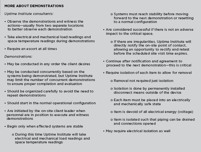
Fundamentally, the Tier Certification process is a binary exercise. The data center facility is compliant with its stated Tier objective, or it is not. So, why then, do Uptime Institute consultants sometimes experience a sinking feeling upon arriving at a site and meeting the team?
Frequently, within the first moments at the facility, it is obvious to the Uptime Institute consultant that nothing is as it should be and the next several days are going to be difficult ones.
Uptime Institute consultants can often tell at first glance whether the client has met the guidance to prepare for the Tier Certification. In fact, the consultants will often know a great deal from the number and tone of questions regarding the demonstrations list.
“You can usually tell if the client has gone through the demonstration list,” said Uptime Institute Consultant Eric Maddison. “I prepare the demonstration list from schematics, so they are not listed in order. It is the client’s obligation to sequence them logically. So it is a good sign if the client has sequenced the demonstrations logically and prepared a program with timing and other information on how they are to perform the demonstration.”
Similarly, Uptime Institute consultants can see whether technicians and appropriate load banks are available. “You can walk into a data hall and see how the load banks are positioned and get a pretty good sense for whether there will be a problem or not,” Brown said, “If the facility has a 1,200-kilowatt load and they only have two large load banks, that’s a dead giveaway that the load banks are too large and not in the right place.”
Similarly, a few quick conversations will tell whether a client has arranged appropriate staffing for the demonstrations. The facility tour provides plenty of opportunity to observe whether the staff on site is knowledgeable about the facility and has practiced the demonstrations. The appropriate level of staff varies from site to site with the complexity of the data center. But, the client needs to have people on site who understand the overall design and can operate each individual piece of equipment as well as respond to unexpected failures or performance issues.
“We start with an in-brief meeting the morning of the first day for every Tier Certification and that usually takes about an hour, and then we do a tour of the facility, which can take anywhere from 2-4 hours, depending on the size of the facility. By the time those are finished, we have a pretty good idea of whether they are in the A, B, C, or D range of preparation. You start to worry if no one can answer the questions you pose, or if they don’t really have a plan or schedule for demonstrations. You can also get a good comfortable feeling if everybody has the answers, and they know where the equipment is and how it works.”
During this first day, the consultants will also determine who the client liaison is, meet the whole client team, and go over the goals of the program and site visit. During the site tour, the consultants will familiarize themselves with the facility, verify it looks as expected, check that valves and breakers are in place, and confirm equipment nameplates.
Having the proper team on site requires a certain amount of planning. Brown said that owners often inadvertently cause a big challenge by letting contractors and vendors go before the site visit. “They’ve done the construction, they’ve done the operations, and they’ve done the commissioning,” he said, “But then the Operations team comes in cold on Monday after everyone else has left. The whole brain trust that knows how the facility systems work and operate just left the site. And there’s a stack of books and binders 2-feet long for the Operations guys to read, good luck.”
Brown described a much better scenario in which the Uptime Institute consultants arrive on site and find, “The Operations team ready to go and the processes and procedures are already written. They are ready to take over on Day 1 and remain in place for 20 years. They can roll through the demonstrations. And they have multiple team members checking each other, just like they were doing maintenance for 5 years together.
“During the demonstrations, they are double checking process and procedures. ‘Oh wait,’ they’ll say, ‘we need to do this.’ They will update the procedure and do the demonstration again. In this case, the site is going to be ready to handover and start working the Monday after we leave. And everybody’s there still trying to finish up that last little bit of understanding the data center, and see that the process and procedures have all the information they need to effectively operate for years to come.”
In these instances, the owner would have positioned the Operations staff in place early in the project, whether that role is filled by a vendor or in-house staff.
In one case, a large insurer staffed a new facility by transferring half the staff from an existing data center and hiring the rest. That way, it had a mix of people who knew the company’s systems and knew how things worked. They were also part of the commissioning process. The experienced people could then train the new hires.
During the demonstration, the team will interrupt the incoming utility power supply and see that the UPS carries the critical load until the engine generators come on line and provide power to the data center and that the cooling system maintains the critical load during the transition.
WHAT CAUSES POOR PERFORMANCE DURING TIER CERTIFICATION?
So with all these opportunities to prepare, why do some Tier Certifications become difficult experiences?
Obviously, lack of preparation tops the list. Brown said, “Often, there’s hubris. ‘I am a savvy owner, and therefore, the construction team knows what they are doing, and they’ll get it right the first time.’” Similarly, clients do not always understand that the Tier Certification is not a rubber stamp. Maddison recalled more than one instance when he arrived on site only to find the site unprepared to actually perform any of the demonstrations.
Failure to understand the isolation requirements, incomplete drawings, design changes made after the Design Certification, and incomplete or abbreviated commissioning can cause headaches too. Achieving complete isolation of equipment, in particular, has proven to be challenging for some owners.
Sometimes clients aren’t familiar with all the features of a product, but more often the client will open the breakers and think it is isolated. Similar situations can arise when closing valves to confirm that a chilled water system is Concurrently Maintainable or Fault Tolerant.
Incomplete or changed drawings are a key source of frustration. Brown recalled one instance when the Tier Certified Design Documents did not show a generator control. And, since each and every system must meet the Tier requirement, the “new” equipment posed a dilemma, as no demonstration had been devised.
More common, though, are changes to design drawings. Brown said, “During every construction there are going to be changes from what’s designed to what’s built; sometimes there are Tier implications. And, these are not always communicated to us, so we discover them on the site visit.”
Poor commissioning will also cause site visit problems. Brown said, “A common view is that commissioning is turning everything on to see if it works. They’ll say, ‘Well we killed the utility power and the generator started. We have some load in there.’ They just don’t understand that load banking only the generator isn’t commissioning.”
He cites an instance in which the chillers weren’t provided the expected cooling. It turned out that cooling tubes were getting clogged by dirt and silt. “There’s no way they did commissioning—proper commissioning—or they would have noticed that.”
Construction delays can compromise commissioning. As Brown said, “Clients expect to have a building handed over on a certain date. Of course there are delays in construction, delays in commissioning, and delays because equipment didn’t work properly when it was first brought in. For any number of reasons the schedule can be pushed. And the commissioning just gets reduced in scope to meet that same schedule.”
Very often, then, the result is that owner finds that the Tier Certification cannot be completed because not everything has been tested thoroughly and things are not working as anticipated.
If the commissioning is compromised or the staff is not prepared, can the facility pass the Tier Certification anyway?
The short answer is yes.
But often these problems are indications of deeper issues that indicate a facility may not meet the performance requirements of the owner, require expensive mechanical and electrical changes, or cause move-in dates to be postponed–or some combination of all three. In these instances, failing the Tier Certification at the specified and expected time may be the least of the owner’s worries.
In these instances and many others, Uptime Institute consultants can—and do—offer useful advice and solutions. Communication is the key because each circumstance is different. In some cases, the solutions, including multiple site visits, can be expensive. In other cases, however, something like a delayed client move-in date can be worked out by rescheduling a site visit.
In addition, Maddison points out the well-prepared clients can manage the expected setbacks that might occur during the site visit. “Often more compartmentalization is needed or more control strategy. Some clients work miracles. They move control panels or put in new breakers overnight.”
But, successful outcomes like that must be planned. Asking questions, preparing Operations teams, scheduling and budgeting for Commissioning, and understanding the value of the Tier Certification can lead to a smooth process and a facility that meets or exceeds client requirements.
The aftermath of a smooth site visit should almost be anticlimactic. Uptime Institute consultants will prepare a Tier Certification Memorandum documenting any remaining issues, listing any documents to be updated, and describing the need for possible follow-on site visits.
And then finally, upon successful completion of the process, the owner receives the Tier Certification of Constructed Facility letter, an electronic foil, and plaque attesting to the performance of the facility.
Uptime Institute’s Chris Brown, Eric Maddison, and Ryan Orr contributed to this article.
Moscow State University Meets HPC Demands
/in Design/by Kevin HeslinHPC supercomputing and traditional enterprise IT facilities operate very differently
By Andrey Brechalov
In recent years, the need to solve complex problems in science, education, and industry, including the fields of meteorology, ecology, mining, engineering, and others, has added to the demand for high-performance computing (HPC). The result is the rapid development of HPC systems, or supercomputers, as they are sometimes called. The trend shows no signs of slowing, as the application of supercomputers is constantly expanding. Research today requires ever more detailed modeling of complex physical and chemical processes, global atmospheric phenomena, and distributed systems behavior in dynamic environments. Supercomputer modeling provides fine results in these areas and others, with relatively low costs.
Supercomputer performance can be described in petaflops (pflops), with modern systems operating at tens of pflops. However, performance improvements cannot be achieved solely by increasing the number of existing computing nodes in a system, due to weight, size, power, and cost considerations. As a result, designers of supercomputers attempt to improve their performance by optimizing their architecture and components, including interconnection technologies (networks) and by developing and incorporating new types of computing nodes having greater computational density per unit of area. These higher-density nodes require the use of new (or well-forgotten old) and highly efficient methods of removing heat. All this has a direct impact on the requirements for site engineering infrastructure.
HPC DATA CENTERS
Supercomputers can be described as a collection of interlinked components and assemblies—specialized servers, network switches, storage devices, and links between the system and the outside world. All this equipment can be placed in standard or custom racks, which require conditions of power, climate, security, etc., to function properly—just like the server-based IT equipment found in more conventional facilities.
Low- or medium-performance supercomputers can usually be placed in general purpose data centers and even in server rooms, as they have infrastructure requirements similar to other IT equipment, except for a bit higher power density. There are even supercomputers for workgroups that can be placed directly in an office or lab. In most cases, however, any data center designed to accommodate high power density zones should be able to host one of these supercomputers.
On the other hand, powerful supercomputers usually get placed in dedicated rooms or even buildings that include unique infrastructure optimized for a specific project. These facilities are pretty similar to general-purpose data centers. However, dedicated facilities for powerful supercomputers host a great deal of high power density equipment, packed closely together. As a result, these facilities must make use of techniques suitable for removing the higher heat loads. In addition, the composition and characteristics of IT equipment for an HPC data center are already known before the site design begins and its configuration does not change or changes only subtly during its lifetime, except for planned expansions. Thus it is possible to define the term HPC data center as a data center intended specifically for placement of a supercomputer.
Figure 1. Types of HPC data center IT equipment
The IT equipment in a HPC data center built using the currently popular cluster-based architecture can be generally divided into two types, each having its own requirements for engineering infrastructure Fault Tolerance and component redundancy (see Figure 1 and Table 1).
Table 1. Types of IT equipment located in HPC data centers
The difference in the requirements for redundancy for the two types of IT equipment is because applications running on a supercomputer usually have a reduced sensitivity to failures of computational nodes, interconnection leaf switches, and other computing equipment (see Figure 2). These differences enable HPC facilities to incorporate segmented infrastructures that meet the different needs of the two kinds of IT equipment.
Figure 2. Generic HPC data center IT equipment and engineering infrastructure.
ENGINEERING INFRASTRUCTURE FOR COMPUTATIONAL EQUIPMENT
Supercomputing computational equipment usually incorporates cutting-edge technologies and has extremely high power density. These features affect the specific requirements for engineering infrastructure. In 2009, the number of processors that were placed in one standard 42U (19-inch rack unit) cabinet at Moscow State University’s (MSU) Lomonosov Data Center was more than 380, each having a thermal design power (TDP) of 95 watts for a total of 36 kilowatts (kW/rack). Adding 29 kW/rack for auxiliary components, such as (e.g. motherboards, fans, and switches brings the total power requirement to 65 kW/rack. Since then the power density for such air-cooled equipment has reached 65 kW/rack.
On the other hand, failures of computing IT equipment do not cause the system as a whole to fail because of the cluster technology architecture of supercomputers and software features. For example, job checkpointing and automated job restart software features enable applications to isolate computing hardware failures and the computing tasks management software ensures that applications use only operational nodes even when some faulty or disabled nodes are present. Therefore, although failures in engineering infrastructure segments that serve computational IT equipment increase the time required to perform computing tasks, these failures do not lead to a catastrophic loss of data.
Supercomputing computational equipment usually operates on single or N+1 redundant power supplies, with the same level of redundancy throughout the electric circuit to the power input. In the case of a single hardware failure, segmentation of the IT loads and supporting equipment limits the effects of the failure to only a part of IT equipment.
Customers often refuse to install standby-rated engine-generator sets, completely relying on utility power. In these cases, the electrical system design is defined by the time required for normal IT equipment shutdown and the UPS system mainly rides through brief power interruptions (a few minutes) in utility power.
Cooling systems are designed to meet similar requirements. In some cases, owners will lower redundancy and increase segmentation without significant loss of operational qualities to optimize capital expense (CapEx) and operations expense (OpEx). However, the more powerful supercomputers expected in the next few years will require the use of technologies, including partial or full liquid cooling, with greater heat removal capacity.
OTHER IT EQUIPMENT
Auxiliary IT equipment in a HPC data center includes air-cooled servers (sometimes as part of blade systems), storage systems, and switches in standard 19-inch racks that only rarely reach the power density level of 20 kW/rack. Uptime Institute’s annual Data Center Survey reports that typical densities are less than 5 kW/rack.
This equipment is critical to cluster functionality; and therefore, usually has redundant power supplies (most commonly N+2) that draw power from independent sources. Whenever hardware with redundant power is applied, the rack’s automatic transfer switches (ATS) are used to ensure the power failover capabilities. The electrical infrastructure for this equipment is usually designed to be Concurrently Maintainable, except that standby-rated engine-generator sets are not always specified. The UPS system is designed to provide sufficient time and energy for normal IT equipment shutdown.
The auxiliary IT equipment must be operated in an environment cooled to 18–27°C, (64–81°F) according to ASHRAE recommendations, which means that solutions used in general data centers will be adequate to meet the heat load generated by this equipment. These solutions often meet or exceed Concurrent Maintainability or Fault Tolerant performance requirements.
ENERGY EFFICIENCY
In recent years, data center operators have put a greater priority on energy efficiency. This focus on energy saving also applies to specialized HPC data centers. Because of the numerous similarities between the types of data centers, the same methods of improving energy efficiency are used. These include the use of various combinations of free cooling modes, higher coolant and set point temperatures, economizers, evaporative systems, and variable frequency drives and pumps as well as numerous other technologies and techniques.
Reusing the energy used by servers and computing equipment is one of the most promising of these efficiency improvements. Until recent years, all that energy had been dissipated. Moreover, based on average power usage efficiency (PUE), even efficient data centers must use significant energy to dissipate the heat they generate.
Facilities that include chillers and first-generation liquid cooling systems generate “low potential heat” [coolant temperatures of 10–15°C (50–59°F), 12–17°C (54–63°F), and even 20–25°C (68–77°F)] that can be used rather than dissipated, but doing so requires significant CapEx and OpEx (e.g., use of heat pumps) that lead to long investment return times that are usually considered unacceptable.
Increasing the heat potential of the liquid coolants improves the effectiveness of this approach, absent direct expansion technologies. And even while reusing the heat load is not very feasible in server-based spaces, there have been positive applications in supercomputing computational spaces. Increasing the heat potential can create additional opportunities to use free cooling in any climate. That allows year-round free cooling in the HPC data center is a critical requirement.
A SEGMENTED HPC DATA CENTER
Earlier this year the Russian company T-Platforms deployed the Lomonosov-2 supercomputer at MSU, using the segmented infrastructure approach. T-Platforms has experience in supercomputer design and complex HPC data center construction in Russia and abroad. When T-Platforms built the first Lomonosov supercomputer, it scored 12th in the global TOP500 HPC ratings. Lomonosov-1 has been used at 100% of its capacity with about 200 tasks waiting in job queue on average. The new supercomputer will significantly expand MSU’s Supercomputing Center capabilities.
The engineering systems for the new facility were designed to support the highest supercomputer performance, combining new and proven technologies to create an energy-efficient scalable system. The engineering infrastructure for this supercomputer was completed in June 2014, and the computing equipment is being gradually added to the system, as requested by MSU. The implemented infrastructure allows system expansion with currently available A-Class computing hardware and perspective generations of IT equipment without further investments in the engineering systems.
THE COMPUTATIONAL SEGMENT
The supercomputer is based on T-Platforms’s A-class high-density computing system and makes use of a liquid cooling system (see Figure 3). A-class supercomputers support designs of virtually any scale. The peak performance of one A-class enclosure is 535 teraflops (tflops) and a system based on it can easily be extended up to more than 100 pflops. For example, the combined performance of the five A-class systems already deployed at MSU reached 2,576 tflops in 2014 (22nd in the November 2014 TOP500) and was about 2,675 tflops in July 2015. This is approximately 50% greater than the peak performance of the entire first Lomonosov supercomputer (1,700 tflops, 58th in the same TOP500 edition). A supercomputer made of about 100 A-class enclosures would perform on par with the Tianhe-2 (Milky Way-2) system at National Supercomputer Center in Guangzhou (China) that leads the current TOP500 list at about 55 pflops.
Figure 3. The supercomputer is based on T-Platforms’s A-class high-density computing system and makes use of a liquid cooling system
All A-class subsystems, including computing and service nodes, switches, and cooling and power supply equipment, are tightly integrated in a single enclosure as modules with hot swap support (including those with hydraulic connections). The direct liquid cooling system is the key feature of the HPC data center infrastructure. It almost completely eliminates air as the medium of heat exchange. This solution improves the energy efficiency of the entire complex by making these features possible:
• IT equipment installed in the enclosure has no fans
• Heat from the high-efficiency air-cooled power supply units (PSU) is removed using water/air heat exchangers embedded in the enclosure
• Electronic components in the cabinet do not require computer room air for cooling
• Heat dissipated to the computer room is minimized because the cabinet is sealed and insulated
• Coolant is supplied to the cabinet at cabinet at 44°C (111°F) with up to 50°C (122°F) outbound under full load, which enables year-round free cooling at ambient summer temperatures of up to 35°C (95°F) and the use of dry coolers without adiabatic systems (see Figure 4)
Figure 4. Coolant is supplied to the auxiliary IT cabinets at 44°C (50°C outbound under full load), which enables year-round free cooling at ambient summer temperatures of up to 35°C and the use of dry coolers without adiabatic systems
In addition noise levels are also low because liquid cooling eliminates powerful node fans that generate noise in air-cooled systems. The only remaining fans in A-Class systems are embedded in the PSUs inside the cabinets, and these fans are rather quiet. Cabinet design contains most of the noise from this source.
INFRASTRUCTURE SUPPORT
The power and cooling systems for Lomonosov-2 follow the general segmentation guidelines. In addition, they must meet the demands of the facility’s IT equipment and engineering systems at full load, which includes up to 64 A-class systems (peak performance over 34 pflops) and up to 80 auxiliary equipment U racks in 42U, 48U, and custom cabinets. At full capacity these systems require 12,000-kW peak electric power capacity.
Utility power is provided by eight 20/0.4-kV substations, each having two redundant power transformers making a total of 16 low-voltage power lines with a power limit of 875 kW/line in normal operation.
Although no backup engine-generator sets have been provisioned, at least 28% of the computing equipment and 100% of auxiliary IT equipment is protected by UPS providing at least 10 minutes of battery life for all connected equipment.
The engineering infrastructure also includes two independent cooling systems: a warm-water, dry-cooler type for the computational equipment and a cold-water, chiller system for auxiliary equipment. These systems are designed for normal operation in temperatures ranging from -35 to+35°C (-31 to +95°F) with year-round free cooling for the computing hardware. The facility also contains an emergency cooling system for auxiliary IT equipment.
The facility’s first floor includes four 480-square-meters (m2) rooms for computing equipment (17.3 kW/m2) and four 280-m2 rooms for auxiliary equipment (3 kW/m2) with 2,700 m2 for site engineering rooms on an underground level.
POWER DISTRIBUTION
The power distribution system is built on standard switchboard equipment and is based on the typical topology for general data centers. In this facility, however, the main function of the UPS is to ride through brief blackouts of the utility power supply for select computing equipment (2,340 kW), all auxiliary IT equipment (510 kW), and engineering equipment systems (1,410 kW). In the case of a longer blackout, the system supplies power for proper shutdown of connected IT equipment.
The UPS system is divided into three independent subsystems. The first is for computing equipment, the second is for auxiliary equipment, and the third is for engineering systems. In fact, the UPS system is deeply segmented because of the large number of input power lines. This minimizes the impact of failures of engineering equipment on supercomputer performance in general.
The segmentation principle is also applied to the physical location of the power supply equipment. Batteries are placed in three separate rooms. In addition, there are three UPS rooms and one switchboard room for the computing equipment that is unprotected by UPS. Figure 5 shows one UPS-battery room pair.
Figure 5. A typical pair of UPS-battery rooms
Three, independent, parallel UPS, each featuring N+1 redundancy (see Figure 6), feed the protected computing equipment. This redundancy, along with bypass availability and segmentation, simplifies UPS maintenance and the task of localizing a failure. Considering that each UPS can receive power from two mutually redundant transformers, the overall reliability of the system meets the owner’s requirements.
Figure 6. Power supply plan for computing equipment
Three independent parallel UPS systems are also used for the auxiliary IT equipment because it requires greater failover capabilities. The topology incorporates a distributed redundancy scheme that was developed in the late 1990s. The topology is based on use of three or more UPS modules with independent input and output feeders (see Figure 7).
Figure 7. Power supply for auxiliary equipment
This system is more economical than a 2N-redundant configuration while providing the same reliability and availability levels. Cable lines connect each parallel UPS to the auxiliary equipment computer rooms. Thus, the computer room has three UPS-protected switchboards. The IT equipment in these rooms, being mostly dual fed, is divided into three groups, each of which is powered by two switchboards. Single-feed and N+1 devices are connected through a local rack-level ATS (see Figure 8).
Figure 8. Single-feed and N+1-redundant devices are connected through a local rack-level ATS
ENGINEERING EQUIPMENT
Some of the engineering infrastructure also requires uninterrupted power in order to provide the required Fault Tolerance. The third UPS system meets this requirement. It consists of five completely independent single UPSs. Technological redundancy is fundamental. Redundancy is applied not to the power lines and switchboard equipment but directly to the engineering infrastructure devices.
The number of UPSs in the group (Figure 9 shows three of five) determines the maximum redundancy to be 4+1. This system can also provide 3+2 and 2N configurations). Most of the protected equipment is at N+1 (see Figure 9).
Figure 9. Power supply for engineering equipment
In general, this architecture allows decommissioning of any power supply or cooling unit, power line, switchboard, UPS, etc., without affecting the serviced IT equipment. Simultaneous duplication of power supply and cooling system components is not necessary.
OVERALL COOLING SYSTEM
Lomonosov-2 makes use of a cooling system that consists of two independent segments, each of which is designed for its own type of IT equipment (see Table 2). Both segments make use of a two-loop scheme with plate heat exchangers between loops. The outer loops have a 40% ethylene-glycol mixture that is used for coolant. Water is used in the inner loops. Both segments have N+1 components (N+2 for dry coolers in the supercomputing segment).
Table 2. Lomonosov makes use of a cooling system that consists of two independent segments, each of which is designed to meet the different requirements of the supercomputing and auxiliary IT equipment.
This system, designed to serve the 64 A-class enclosures, has been designated the hot-water segment. Its almost completely eliminates the heat from extremely energy-intensive equipment without chillers (see Figure 10). Dry coolers dissipate all the heat that is generated by the supercomputing equipment up to ambient temperatures of 35°C (95°F). Power is required only for the circulation pumps of both loops, dry cooler fans, and automation systems.
Figure 10. The diagram shows the cooling system’s hot water segment.
Under full load and in the most adverse conditions, the instant PUE would be expected to be about 1.16 for the fully deployed system of 64 A-class racks (see Figure 11).
Figure 11. Under full load and under the most adverse conditions, the instant PUE (power utilization efficiency would be expected to be about 1.16 for the fully deployed system of 64 A-class racks)
The water in the inner loop has been purified and contains corrosion inhibitors. It is supplied to computer rooms that will contain only liquid-cooled computer enclosures. Since the enclosures do not use computer room air for cooling, the temperature in these rooms is set at 30°C (86°F) and can be raised to 40°C (104°F) without any influence on the equipment performance. The inner loop piping is made of PVC/CPVC (polyvinyl chloride/chlorinated polyvinyl chloride) thus avoiding electrochemical corrosion.
COOLING AUXILIARY IT EQUIPMENT
It is difficult to avoid using air-cooled IT equipment, even in a HPC project, so MSU deployed a separate cold-water [12–17°C (54–63°F)] cooling system. The cooling topology in these four spaces is almost identical to the hot-water segment deployed in the A-class rooms, except that chillers are used to dissipate the excess heat from the auxiliary IT spaces to the atmosphere. In the white spaces, temperatures are maintained using isolated Hot Aisles and in-row cooling units. Instant PUE for this isolated system is about 1.80, which is not a particularly efficient system (see Figure 12).
Figure 12. In white spaces, temperatures are maintained using isolated hot aisles and in-row cooling units.
If necessary, some of the capacity of this segment can be used to cool the air in the A-class computing rooms. The capacity of the cooling system in these spaces can meet up to 10% of the total heat inflow in each of the A-class enclosures. Although sealed, they still heat the computer room air through convection. But in fact, passive heat radiation from A-class enclosures is less than 5% of the total power consumed by them.
EMERGENCY COOLING
An emergency-cooling mode exists to deal with utility power input blackouts, when both cooling segments are operating on power from the UPS. In emergency mode, each cooling segment has its own requirements. As all units in the first segment (both pump groups, dry coolers, and automation) are connected to the UPS, the system continues to function until the batteries discharge completely.
In the second segment, the UPS services only the inner cooling loop pumps, air conditioners in computer rooms, and automation equipment. The chillers and outer loop pumps are switched off during the blackout.
Since the spaces allocated for cooling equipment are limited, it was impossible to use a more traditional method of stocking cold water at the outlet of the heat exchangers (see Figure 13). Instead, the second segment of the emergency system features accumulator tanks with water stored at a lower temperature than in the loop [about 5°C (41°F) with 12°C (54°F) in the loop] to keep system parameters within a predetermined range. Thus, the required tank volume was reduced to 24 cubic meters (m3) instead of 75 m3, which allowed the equipment to fit in the allocated area. A special three-way valve allows mixing of chilled water from the tanks into the loop if necessary. Separate small low-capacity chillers (two 55-kW chillers) are responsible for charging the tanks with cold water. The system charges the cold-water tanks in about the time it takes to charge the UPS batteries.
Figure 13. Cold accumulators are used to keep system parameters within a predetermined range.
MSU estimates that segmented cooling with a high-temperature direct water cooling segment reduces its total cost of ownership by 30% compared to data center cooling architectures based on direct expansion (DX) technologies. MSU believes that this project shows that combining the most advanced and classical technologies and system optimization allows significant savings on CapEx and OpEx while keeping the prerequisite performance, failover, reliability and availability levels.
Andrey Brechalov
Andrey Brechalov is Chief Infrastructure Solutions Engineer of T-Platforms, a provider of high performance computing (HPC) systems, services, and solutions headquartered in Moscow, Russia. Mr. Brechalov has responsibility for building engineering infrastructures for supercomputers SKIF K-1000, SKIF Cyberia, and MSU Lomonosov-2 as well as smaller supercomputers by T-Platforms. He has worked for more than 20 years in computer industry including over 12 years in HPC and specializes in designing, building, and running supercomputer centers.
Achieving Uptime Institute Tier III Gold Certification of Operational Sustainability
/in Operations/by Kevin HeslinVantage Data Centers certifies design, facility, and operational sustainability at its Quincy, WA site
By Mark Johnson
In February 2015, Vantage Data Centers earned Tier III Gold Certification of Operational Sustainability (TCOS) from Uptime Institute for its first build at its 68-acre Quincy, WA campus. This project is a bespoke design for a customer that expects a fully redundant, mission critical, and environmentally sensitive data center environment for its company business and mission critical applications.
Vantage believes that TCOS is a validation that its practices, procedures, and facilities management are among the best in the world. Uptime Institute professionals verified not only that all the essential components for success are in place but also that each team member demonstrates tangible evidence of adhering strictly to procedure. It also provides verification to potential tenants that everything from maintenance practices to procedures, training, and documentation is done properly.
Recognition at this level is a career highlight for data center operators and engineers—the equivalent of receiving a 4.0-grade-point average from Vantage’s most elite peers. This recognition of hard work is a morale booster for everyone involved—including the tenant, vendors, and contractors, who all worked together and demonstrated a real commitment to process in order to obtain Tier Certification at this level. This commitment from all parties is essential to ensuring that human error does not undermine the capital investment required to build a 2N+1 facility capable of supporting up to 9 megawatts of critical load.
BUILDING THE RIGHT TEAM
The right team is the foundation of an effectively run data center. Assembling the team was Vantage’s highest priority and required a careful examination of the organization’s strengths and weaknesses, culture, and appeal to prospective employees.
Having a team of skilled heating, ventilation and air conditioning (HVAC) mechanics, electricians, and other highly trained experts in the field is crucial to running a data center effectively. Vantage seeks technical expertise but also demonstrable discipline, accountability, responsibility, and drive in its team members.
Beyond these must-have features is a subset of nice-to-have characteristics, and at the top of that list is diversity. A team that includes diverse skill sets, backgrounds, and expertise not only ensures a more versatile organization but also enables more work to be done in-house. This is a cost saving and quality control measure, and yet another way to foster pride and ownership in the team.
Time invested upfront in selecting the best team members helps reduce headaches down the road and gives managers a clear reference for what an effective hire looks like. A poorly chosen hire costs more in the long run, even if it seems like an urgent decision in the moment, so a rigorous, competency-based interview process is a must. If the existing team does not unanimously agree on a potential hire, organizations must move on and keep searching until the right person is found.
Recruiting is a continuous process. The best time to look for top talent is before it’s desperately needed. Universities, recruiters, and contractors can be sources of local talent. The opportunity to join an elite team can be a powerful inducement to promising young talent.
TRAINING
The first component of a successful training program is fostering on-the-job learning in every situation. Structuring on the job learning requires that senior staff work closely with junior staff and employees with different types and levels of expertise match up with each other to learn from one another. Having a diverse hiring strategy can lead to the creation of small educational partnerships.
It’s impossible to ensure the most proficient team members will be available for every problem and shift, so it’s essential that all employees have the ability to maintain and operate the data center. Data center management should encourage and challenge employees to try new tasks and require peer reviews to demonstrate competency. Improving overall competency reduces over-dependence on key employees and helps encourage a healthier work-life balance.
Formalized, continuous training programs should be designed to evaluate and certify employees using a multi-level process through which varying degrees of knowledge, skill, and experience are attained. The objectives are ensuring overall knowledge, keeping engineers apprised of any changes to systems and equipment, and identifying and correcting any knowledge shortfalls.
PROCEDURES
Ultimately, discipline and adherence to fine-tuned procedures are essential to operational excellence within a data center. The world’s best-run data centers even have procedures on how to write procedures. Any element that requires human interaction or consideration—from protective equipment to approvals—should have its own section in the operating procedures, including step-by-step instructions and potential risks. Cutting corners, while always tempting, should be avoided; data centers live and die by procedure.
Managing and updating procedure is equally important. For example, major fires broke out just a few miles away from Vantage’s Quincy facility not long ago,. The team carefully monitored and tracked the fires, noting that the fires were still several miles away and seemingly headed away from our site. That information, however, was not communicated directly to the largest customer at the site, which called in the middle of the night to ask about possible evacuation and the recovery plan. Vantage collaborated with the customer to develop a standardized system for emergency notifications, which it incorporated in its procedures, to mitigate the possibility of future miscommunications.
Once procedures are created, they should go through a careful vetting process involving a peer review, to verify the technical accuracy of each written step, including lockout/tagout and risk identification. Vetting procedures means physically walking on site and carrying out each step to validate the procedure for accuracy and precision.
Effective work order management is part of a well-organized procedure. Vantage’s work order management process:
• Predefines scope of service documents to stay ahead of work
• Manages key work order types, such as corrective work orders, preventive maintenance work orders, and project work orders
• Measures and reports on performance at every step
Maintaining regular, detailed reporting practices adds yet another layer of procedural security. A work order system can maintain and manage all action items. Reporting should be reviewed with the parties involved in each step, with everyone held accountable for the results and mistakes analyzed and rectified on an ongoing basis.
Peer review is also essential to maintaining quality methods of procedure (MOPs) and standard operating procedures (SOPs). As with training, pairing up employees for peer review processes helps ensure excellence at all stages.
IMPLEMENTATION AND DISCIPLINE
Disciplined enforcement of processes that are proven to work is the most important component of effective standards and procedures. Procedures are not there to be followed when time allows or when it is convenient. For instance, if a contractor shows upon site without a proper work order or without having followed proper procedure, that’s not an invitation to make an exception. Work must be placed on hold until procedures can be adhered to, with those who did not follow protocol bearing accountability for the delay.
For example, Vantage developed emergency operating procedures (EOPs) for any piece of equipment that could possibly fail. And, sure enough, an uninterruptible power supply failed (UPS) during routine maintenance. Because proper procedures had been developed and employees properly trained, they followed the EOP to the letter, solving the problem quickly and entirely eliminating human error from the process. The loads were diverted, the crisis averted, and everything was properly stabilized to work on the UPS system without fear of interrupting critical loads.
Similarly, proper preparation for maintenance procedures eliminates risk of losing uptime during construction. Vantage develops and maintains scope of service documents for each piece of equipment in the data center, and what is required to maintain them. The same procedures for diverting critical loads for maintenance were used during construction to ensure the build didn’t interfere with critical infrastructure despite the load being moved more than 20 times.
Transparency and open communication between data center operators and customers while executing preventative maintenance is key. Vantage notifies the customer team at the Quincy facility prior to executing any preventative maintenance that may pose a risk to their data haul. The customer then puts in a snap record, which notifies their internal teams about the work. Following these procedures and getting the proper permissions ensures that the customer won’t be subjected to any uncontrolled risk and covers all bases should any unexpected issues arise.
When procedure breaks down and fails due to lack of employee discipline, it puts both the company and managerial staff in a difficult position. First, the lack of discipline undermines the effectiveness of the procedures. Second, management must make a difficult choice—retrain or replace the offending employee. For those given a second chance, managers put their own jobs on the line—a tough prospect in a business that requires to-the-letter precision at every stage.
To ensure that discipline is instilled deeply in every employee, it’s important that the team take ownership of every component. Vantage keeps all its work in-house and consistently trains its employees in multiple disciplines rather than outsourcing. This makes the core team better and more robust and avoids reliance on outside sources. Additionally, Vantage does not allow contractors to turn breakers on and off, because the company ultimately bears the responsibility of an interrupted load. Keeping everything under one roof and knowing every aspect of the data center inside and out is a competitive advantage.
Vantage’s accomplishment of Tier III Gold Certification of Operational Sustainability validates everything the company does to develop and support its operational excellence.
Mark Johnson
Mark Johnson is Site Operations Manger at Vantage Data Centers. Prior to joining Vantage, Mr. Johnson was data center facilities manager at Yahoo. He was responsible for the critical facilities infrastructure for the Wenatchee and Quincy, WA, data centers. He was also a CITS Facilities Engineer at Level 3 Communications, where he was responsible for the critical facilities infrastructure for two Sunnyvale, CA, data centers. Before that, Mr. John was an Engineer III responsible for critical facilities at VeriSign, where he was responsible for two data centers, and a chief facilities engineer at Abovenet.
Economizers in Tier Certified Data Centers
/in Design/by Kevin HeslinAchieving the efficiency and cost savings benefits of economizers without compromising Tier level objectives
By Keith Klesner
In their efforts to achieve lower energy use and greater mechanical efficiency, data center owners and operators are increasingly willing to consider and try economizers. At the same time, many new vendor solutions are coming to market. In Tier Certified data center environments, however, economizers, just as any other significant infrastructure system, must operate consistently with performance objectives.
Observation by Uptime Institute consultants indicates that roughly one-third of new data center construction designs include an economizer function. Existing data centers are also looking at retrofitting economizer technologies to improve efficiency and lower costs. Economizers use external ambient air to help cool IT equipment. In some climates, the electricity savings from implementing economizers can be so significant that the method has been called “free cooling.” But, all cooling solutions require fans, pumps, and/or other systems that draw power; thus, the technology is not really free and the term economizers is more accurate.
When The Green Grid surveyed large 2,500-square foot data centers in 2011, 49% of the respondents (primarily U.S. and European facilities) reported using economizers and another 24% were considering them. In the last 4 years, these numbers have continued to grow. In virtually all climatic regions, adoption of these technologies appears to be on the rise. Uptime Institute has seen an increase in the use of economizers in both enterprise and commercial data centers, as facilities attempt to lower their power usage effectiveness (PUE) and increase efficiency. This increased adoption is due in large part to fears about rising energy costs (predicted to grow significantly in the next 10 years). In addition, outside organizations, such as ASHRAE, are advocating for greater efficiencies, and internal corporate and client sustainability initiatives at many organizations drive the push to be more efficient and reduce costs.
The marketplace includes a broad array of economizer solutions:
• Direct air cooling: Fans blow cooler outside air into a data center, typically through filters
• Indirect evaporative cooling: A wetted medium or water spray promotes evaporation to supply cool air into a data center
• Pumped refrigerant dry coolers: A closed-loop fluid, similar to an automotive radiator, rejects heat to external air and provides cooling to the data center
• Water-side economizing: Traditional cooling tower systems incorporating heat exchangers bypass chillers to cool the data center
IMPLICATIONS FOR TIER
Organizations that plan to utilize an economizer system and desire to attain Tier Certification must consider how best to incorporate these technologies into a data center in a way that meets Tier requirements. For example, Tier III Certified Constructed Facilities have Concurrently Maintainable critical systems. Tier IV Certified Facilities must be Fault Tolerant.
Some economizer technologies and/or their implementation methods can affect critical systems that are integral to meeting Tier Objectives. For instance, many technologies were not originally designed for data center use, and manufacturers may not have thought through all the implications.
For example, true Fault Tolerance is difficult to achieve and requires sophisticated controls. Detailed planning and testing is essential for a successful implementation. Uptime Institute does not endorse or recommend any specific technology solution or vendor; each organization must make its own determination of what solution will meet the business, operating, and environmental needs of its facility.
ECONOMIZER TECHNOLOGIES
Economizer technologies include commercial direct air rooftop units, direct air plus evaporative systems, indirect evaporative cooling systems, water-side economizers, and direct air plus dry cooler systems.
DIRECT AIR
Direct air units used as rooftop economizers are often the same units used for commercial heating, ventilation, and air-conditioning (HVAC) systems. Designed for office and retail environments, this equipment has been adapted for 24 x 7 applications. Select direct air systems also use evaporative cooling, but all of them combine of them combine direct air and multi-stage direct expansion (DX) or chilled water. These units require low capital investment because they are generally available commercially, service technicians are readily available, and the systems typically consume very little water. Direct air units also yield good reported PUE (1.30–1.60).
On the other hand, commercial direct air rooftop units may require outside air filtration, as many units do not have adequate filtration to prevent the introduction of outside air directly into critical spaces, which increases the risk of particulate contamination.
Outside air units suitable for mission critical spaces require the capability of 100% air recirculation during certain air quality events (e.g., high pollution events and forest or brush fires) that will temporarily negate the efficiency gains of the units.
Figure 1. A direct expansion unit with an air-side economizer unit provides four operating modes including direct air, 100% recirculation, and two mixed modes. It is a well-established technology, designed to go from full stop (no power) to full cooling in 120 seconds or less, and allowing for PUE as low as 1.30-1.40.
Because commercial HVAC systems do not always meet the needs of mission critical facilities, owners and operators must identify the design limitations of any particular solution. Systems may integrate critical cooling and the air handling unit or provide a mechanical solution that incorporates air handling and chilled water. These units will turn off the other cooling mechanism when outside air cooling permits. Units that offer dual modes are typically not significantly more expensive. These commercial units require reliable controls that ensure that functional settings align with the mission critical environment. It is essential that the controls sequence be dialed in before performing thorough testing and commissioning of all control possibilities (see Figure 1). Commercial direct air rooftop units have been used successfully in Tier III and Tier IV applications (see Figure 2).
Figure 2. Chilled water with air economizer and wetting media provides nine operating modes including direct air plus evaporative cooling. With multiple operating modes, the testing regimen is extensive (required for all modes).
A key step in adapting commercial units to mission critical applications is considering the data center’s worst-case scenario. Most commercial applications are rated at 95°F (35°C), and HVAC units will typically allow some fluctuation in temperature and discomfort for workers in commercial settings. The temperature requirements for data centers, however, are more stringent. Direct air or chilled water coils must be designed for peak day—the location’s ASHRAE dry bulb temperature and/or extreme maximum wet bulb temperature. Systems must be commissioned and tested in Tier demonstrations for any event that would require 100% recirculation. If the unit includes evaporative cooling, makeup (process) water must meet all Tier requirements or the evaporative capacity must be excluded from the Tier assessment.
In Tier IV facilities, Continuous Cooling is required, including during any transition from utility power to engine generators. Select facilities have achieved Continuous Cooling using chilled water storage. In the case of one Tier IV site, the rooftop chilled water unit included very large thermal storage tanks to provide Continuous Cooling via the chilled water coil.
Controller capabilities and building pressure are also considerations. As these are commercial units, their controls are usually not optimized for the transition of power from the utility to the engine-generator sets and back. Typically, over- or under-pressure imbalance in a data center increases following a utility loss or mode change due to outside air damper changes and supply and exhaust fans starting and ramping up. This pressure can be significant. Uptime Institute consultants have even seen an entire wall blow out from over-pressure in a data hall. Facility engineers have to adjust controls for the initial building pressure and fine-tune them to adjust to the pressure in the space.
To achieve Tier III objectives, each site must determine if a single or shared controller will meet its Concurrent Maintainability requirements. In a Tier IV environment, Fault Tolerance is required in each operating mode to prevent a fault from impacting the critical cooling of other units. It is acceptable to have multiple rooftop units, but they must not be on a single control or single weather sensor/control system component. It is important to have some form of distributed or lead-lag (master/slave) system to control these components and enabling them to be operate in a coordinated fashion with no points of commonality. If any one component fails, the master control system will switch to the other unit, so that a fault will not impact critical cooling. For one Tier IV project demonstration, Uptime Institute consultants found additional operating modes while on site. Each required additional testing and controls changes to ensure Fault Tolerance.
DIRECT AIR PLUS EVAPORATIVE SYSTEMS
One economizer solution on the market, along with many other similar designs, involves a modular data center with direct air cooling and wetted media fed from a fan wall. The fan wall provides air to a flooded Cold Aisle in a layout that includes a contained Hot Aisle. This proprietary solution is modular and scalable, with direct air cooling via an air optimizer. This system is factory built with well-established performance across multiple global deployments. The systems have low reported PUEs and excellent partial load efficiency. Designed as a prefabricated modular cooling system and computer room, the system comes with a control algorithm that is designed for mission critical performance.
These units are described as being somewhat like a “data center in a box” but without the electrical infrastructure, which must be site designed to go with the mechanical equipment. Cost may be another disadvantage, as there have been no deployments to date in North America. In operation, the system determines whether direct air or evaporative cooling is appropriate, depending upon external temperature and conditions. Air handling units are integrated into the building envelope rather than placed on a rooftop.
Figure 3. Bladeroom’s prefabricated modular data center uses direct air with DX and evaporative cooling.
One company has used a prefabricated modular data center solution with integrated cooling optimization between indirect, evaporative, and DX cooling in Tier III facilities. In these facilities, a DX cooling system provides redundancy to the evaporative cooler. If there is a critical failure of the water supply to the evaporative cooler (or the water pump, which is measured by a flow switch), the building management system starts DX cooling and puts the air optimizer into full recirculation mode. In this set up, from a Tier objective perspective, the evaporative system and water system supporting it are not critical systems. Fans are installed in an N+20% configuration to provide resilience. The design plans for DX cooling at less than 6% of the year at the installations in Japan and Australia and acts as redundant mechanical cooling for the remainder of the year, able to meet 100% of the IT capacity. The redundant mechanical cooling system itself is an N+1 design (See Figures 3 and 4).
Figure 4. Supply air from the Bladeroom “air optimizer” brings direct air with DX and evaporative cooling into flooded cold aisles in the data center.
This data center solution has seen multiple Tier I and Tier II deployments, as well as several Tier III installations, providing good efficiency results. Achieving Tier IV may be difficult with this type of DX plus evaporative system because of Compartmentalization and Fault Tolerant capacity requirements. For example; Compartmentalization of the two different air optimizers is a challenge that must be solved; the louvers and louver controls in the Cold Aisles are not Fault Tolerant and would require modification, and Compartmentalization of electrical controls has not been incorporated into the concept (for example, one in the Hot Aisle and one in the Cold Aisle).
INDIRECT EVAPORATIVE COOLING SYSTEMS
Another type of economizer employs evaporative cooling to indirectly cool the data center using a heat exchanger. There are multiple suppliers of these types of systems. New technologies incorporate cooling media of hybrid plastic polymers or other materials. This approach excludes outside air from the facility. The result is a very clean solution; pollutants, over-pressure/under-pressure, and changes in humidity from outside events like thunderstorms are not concerns. Additionally, a more traditional, large chilled water plant is not necessary (although makeup water storage will be needed) because chilled water is not required.
As with many economizing technologies, greater efficiency can enable facilities to avoid upsizing the electrical plant to accommodate the cooling. A reduced mechanical footprint may mean lower engine-generator capacity, fewer transformers and switchgear, and an overall reduction in the often sizable electrical generation systems traditionally seen in a mission critical facility. For example, one data center eliminated an engine generator set and switchgear, saving approximately US$1M (although the cooling units themselves were more expensive than some other solutions on the market).
The performance of these types of systems is climate dependent. No external cooling systems are generally required in more northern locations. For most temperate and warmer climates some supplemental critical cooling will be needed for hotter days during the year. The systems have to be sized appropriately; however, a small supplemental DX top-up system can meet all critical cooling requirements even in warmer climates. These cooling systems have produced low observed PUEs (1.20 or less) with good partial load PUEs. Facilities employing these systems in conjunction with air management systems and Hot Aisle containment to supply air inlet temperatures up to the ASHRAE recommendation of 27°C (81°F) have achieved Tier III certification with no refrigeration or DX systems needed.
Indirect air/evaporative solutions have two drawbacks, a relative lack of skilled service technicians to service the units and high water requirements. For example, one fairly typical unit on the market can use approximately 1,500 cubic meters (≈400,000 gallons) of water per megawatt annually. Facilities need to budget for water treatment and prepare for a peak water scenario to avoid an impactful water shortage for critical cooling.
Makeup water storage must meet Tier criteria. Water treatment, distribution, pumps, and other parts of the water system must meet the same requirements as the critical infrastructure. Water treatment is an essential, long-term operation performed using methods such as filtration, reverse osmosis, or chemical dosing. Untreated or insufficiently treated water can potentially foul or scale equipment, and thus, water-based systems require vigilance.
It is important to accurately determine how much makeup water is needed on site. For example, a Tier III facility requires 12 hours of Concurrently Maintainable makeup water, which means multiple makeup water tanks. Designing capacity to account for a worst-case scenario can mean handling and treating a lot of water. Over the 20-30 year life of a data center, thousands of gallons (tens of cubic meters) of stored water may be required, which becomes a site planning issue. Many owners have chosen to exceed 12 hours for additional risk avoidance. For more information, refer to Accredited Tier Designer Technical Paper Series: Makeup Water).
WATER-SIDE ECONOMIZERS
Water-side economizer solutions combine a traditional water-cooled chilled water plant with heat exchangers to bypass chiller units. These systems are well known, which means that skilled service technicians are readily available. Data centers have reduced mechanical plant power consumption from 10-25% using water-side economizers. Systems of this type provide perhaps the most traditional form of economizer/mechanical systems power reduction. The technology uses much of the infrastructure that is already in place in older data centers, so it can be the easiest option to adopt. These systems introduce heat exchangers, so cooling comes directly from cooling towers and bypasses chiller units. For example, in a climate like that in the northern U.S., a facility can run water through a cooling tower during the winter to reject heat and supply the data center with cool water without operating a chiller unit.
Controls and automation for transitions between chilled water and heat exchanger modes are operationally critical but can be difficult to achieve smoothly. Some operators may bypass the water-side economizers if they don’t have full confidence in the automation controls. In some instances, operators may choose not to make the switch when a facility is not going to utilize more than four or six hours of economization. Thus energy savings may actually turn out to be much less than expected.
Relatively high capital expense (CapEx) investment is another drawback. Significant infrastructure must be in place on Day 1 to account for water consumption and treatment, heat exchangers, water pumping, and cooling towers. Additionally, the annualized PUE reduction that results from water-side systems is often not significant, most often in the 0.1–0.2 range. Data center owners will want a realistic cost/ROI analysis to determine if this cooling approach will meet business objectives.
Figure 5. Traditional heat exchanger typical of a water-side economizer system.
Water-side economizers are proven in Tier settings and are found in multiple Tier III facilities. Tier demonstrations are focused on the critical cooling system, not necessarily the economizer function. Because the water-side economizer itself is not considered critical capacity, Tier III demonstrations are performed under chiller operations, as with typical rooftop units. Demonstrations also include isolation of the heat exchanger systems and valves, and economizer control of functions is critical (see Figures 5 and 6). However, for Tier IV settings where Fault Tolerance is required, the system must be able to respond autonomously. For example, one data center in Spain had an air-side heat recovery system with a connected office building. If an economizer fault occurred, the facility would need to ensure it would not impact the data center. The solution was to have a leak detection system that would shut off the economizer to maintain critical cooling of the data hall in isolation.
Figure 6. The cooling tower takes in hot air from the sides and blows hot, wet air out of the top, cooling the condenser water as it falls down the cooling tower. In operation it can appear that steam is coming off the unit, but this is a traditional cooling tower.
CRACs WITH PUMPED REFRIGERANT ECONOMIZER
Another system adds an economizer function to a computer room air conditioner (CRAC) unit using a pumped liquid refrigerant. In some ways, this technology operates similarly to standard refrigeration units, which use a compressor to convert a liquid refrigerant to a gas. However, instead of using a compressor, newer technology blows air across a radiator unit to reject the heat externally without converting the liquid refrigerant to a gas. This technology has been implemented and tested in several data centers with good results in two Tier III facilities.
The advantages of this system include low capital cost compared to many other mechanical cooling solutions. These systems can also be fairly inexpensive to operate and require no water. Because they use existing technology that has been modified just slightly, it is easy to find service technicians. It is a proven cooling method with low estimated PUE (1.25–1.35), not quite as much as some modern CRACs that yield 1.60–1.80 PUE, but still substantial. These systems offer distributed control of mode changes. In traditional facilities, switching from chillers to coolers typically happens using one master control. A typical DX CRAC installation will have 10-12 units (or even up to 30) that will self-determine the cooling situation and individually select the appropriate operating mode. Distributed control is less likely to cause a critical cooling problem even if one or several units fail. Additionally these units do not use any outside air. They recirculate inside air, thus avoiding any outside air issues like pollution and humidity.
The purchase of DX CRAC units with dry coolers does require more CapEx investment, a 50–100% premium over traditional CRACs.Other cooling technologies may offer higher energy efficiency. Additional space is required for the liquid pumping units, typically on the roof or beside the data center.
Multiple data centers that use this technology have achieved Tier III Certification. From a Tier standpoint, these CRACs are the same as the typical CRAC. In particular, the distributed control supports Tier III requirements, including Concurrent Maintainability. The use of DX CRAC systems needs to be considered early in the building design process. For example, the need to pump refrigerant limits the number of building stories. With a CRAC in the computer room and condenser units on the roof, two stories seem to be the building height limit at this time. The suitability of this solution for Tier IV facilities is still undetermined. The local control mechanism is an important step to Fault Tolerance, and Compartmentalization of refrigerant and power must be considered.
OPERATIONS CONSIDERATIONS WITH ECONOMIZERS
Economizer solutions present a number of operational ramifications, including short- and long-term impacts, risk, CapEx, commissioning, and ongoing operating costs. An efficiency gain is one obvious impact; although, an economizer can increase some operational maintenance expenses:
• Several types require water filtration and/or water treatment
• Select systems require additional outside air filtration
• Water-side economizing can require additional cooling tower maintenance
Unfortunately in certain applications, economization may not be a sustainable practice overall, from either a cost or “green” perspective, even though it reduces energy use. For example, high water use is not an ideal solution in dry or water-limited climates. Additionally, extreme use of materials such as filters and chemicals for water treatment can increase costs and also reduce the sustainability of some economizer solutions.
CONCLUSION
Uptime Institute experience has amply shown that, with careful evaluation, planning, and implementation, economizers can be effective at reducing energy use and costs and lowering energy consumption without sacrificing performance, availability, or Tier objectives. Even so, modern data centers have begun to see diminishing PUE returns overall, with many data centers experiencing a leveling off after initial gains. These and all facilities can find it valuable to consider whether investing in mechanical efficiency or broader IT efficiency measures such as server utilization and decommissioning will yield the most significant gains and greater holistic efficiencies.
Economizer solutions can introduce additional risks into the data center, where changes in operating modes increase the risk of equipment failure or operator error. These multi-modal systems are inherently more complex and have more components than traditional cooling solutions. In the event of a failure, operators must know how to manually isolate the equipment or transition modes to ensure critical cooling is maintained.
Any economizer solution must fit both the uptime requirement and business objective, especially if it uses newer technologies or was not originally designed for mission critical facilities. Equally important is ensuring that system selection and installation takes Tier requirements into consideration.
Many data centers with economizers have attained Tier Certification; however, in the majority of facilities, Uptime Institute consultants discovered flaws in the operational sequences or system installation during site inspections that were defeating Tier objectives. In all cases so far, the issues were correctible, but extra diligence is required.
Many economizer solutions are newer technologies, or new applications of existing technology outside of their original intended environment; therefore, careful attention should be paid to elements such as control systems to ensure compatibility with mission critical data center operation. Single shared control systems or mechanical system control components are a problem. A single controller, workstation, or weather sensor may fault or require removal from service for maintenance/upgrade over the lifespan of a data center. Neither the occurrence of a component fault nor taking a component offline for maintenance should impact critical cooling. These factors are particularly important when evaluating the impact of economizers on a facility’s Tier objective.
Despite the drawbacks and challenges of properly implementing and managing economizers, their increased use represents a trend for data center operational and ecological sustainability. For successful economizer implementation, designers and owners need to consider the overarching design objectives and data center objectives to ensure those are not compromised in pursuit of efficiency.
ECONOMIZER SUCCESS STORY
Digital Realty’s Profile Park facility in Ireland implemented compressor-less cooling by employing an indirect evaporative economizer, using technology adapted from commercial applications. The system is a success, but it took some careful consideration, adaptation, and fine-tuning to optimize the technology for a Tier III mission critical data center.
Figure 7. The unit operates as a scavenger air system (red area at left) taking the external air and running it across a media. That scavenger air is part of the evaporative process, with the air used to cool the media directly or cool the return air. This image shows summer operation where warm outside air is cooled by the addition of moisture. In winter, outside air cools the return air.
Achieving the desired energy savings first required attention to water (storage, treatment, and consumption). The water storage needs were significant—approximately 60,000 liters for 3.8-megawatts (MW), equivalent to about 50,000 gallons. Water treatment and filtration are critical in this type of system and was a significant challenge. The facility implemented very fine filtration at a particulate size of 1 micron (which is 10 times stricter than would typically be required for potable water). This type of indirect air system eliminates the need for chiller units but does require significant water pressure.
To achieve Tier III Certification, the system also had to be Concurrently Maintainable. Valves between the units and a loop format with many valves separating units, similar to what would be used with a chilled water system, helped the system meet the Concurrent Maintainability requirement. Two values in series are located between each unit on a bi-directional water loop (see Figure 7 and 8).
As with any installation that makes use of new technology, the facility required additional testing and operations sequence modification for a mission critical Tier III setting. For example, initially the units were overconsuming power, not responding to a loss of power as expected, and were draining all of the water when power was lost. After adjustments, the system performance was corrected.
Figure 8 (a and b). The system requires roughly twice the fan energy needed for a lot of typical rooftop units or CRACs but does not use a compressor refrigeration unit, which does reduce some of the energy use. Additionally, the fans themselves are high efficiency with optimized motors. Thus, while the facility has approximately twice the number of fans and twice the airflow, it can run many more of the small units more efficiently.
Ultimately, this facility with its indirect cooling system was Tier III Certified, proving that it is possible to sustain mechanical cooling year-round without compressors. Digital Realty experienced a significant reduction in PUE with this solution, improving from 1.60 with chilled water to 1.15. With this anticipated annualized PUE reduction, the solution is expected to result in approximately €643,000 (US$711,000) in savings per year. Digital Realty was recognized with an Uptime Institute Brill Award for Efficient IT in 2014.
CHOOSING THE RIGHT ECONOMIZER SOLUTION FOR YOUR FACILITY
Organizations that are considering implementing economizers—whether retrofitting an existing facility or building a new one—have to look at a range of criteria. The specifications of any one facility need to be explored with mechanical, electrical, plumbing (MEP), and other vendors, but key factors to consider are:
Geographical area/climate: This is perhaps the most important factor in determining which economizer technologies are viable options for a facility. For example, direct outside air can be a very effective solution in northern locations that have an extended cold winter, and select industrial environments can preclude the use of outside air because of high pollutant content, other solutions will work better in tropical climates versus arid regions where water-side solutions are less appropriate.
New build or retrofit: Retrofitting an existing facility can eliminate available economizer options, usually due to space considerations but also because systems such as direct air plus evaporative and DX CRAC need to be incorporated at the design stage as part of the building envelope.
Supplier history: Beware of suppliers from other industries entering the data center space. Limited experience with mission critical functionality including utility loss restarts, control architecture, power consumption, and water consumption can mean systems need to be substantially modified to conform to 24 x 7 data center operating objectives. New suppliers are entering into the data center market, but consider which of them will be around for the long term before entering into any agreements to ensure parts supplies and skilled service capabilities will be available to maintain the system throughout its life cycle.
Financial considerations: Economizers have both CapEx and operating expense (OpEx) impact. Whether an organization wants to invest capital up front or focus on long-term operating budgets depends on the business objectives.
Some general CapEx/OpEx factors to keep in mind include:
• Select newer cooling technology systems are high cost, and thus require more up front CapEx.
• A low initial capital outlay with higher OpEx may be justified in some settings.
• Enterprise owners/operators should consider insertion of economizers into the capital project budget with long-term savings justifications.
ROI objectives: As an organization, what payback horizon is needed for significant PUE reduction? Is it one-two years, five years, or ten? The assumptions for the performance of economizer systems should utilize real-world savings, as expectations for annual hours of use and performance should be reduced from the best-case scenarios provided by suppliers. A simple payback model should be less than three to five years from the energy savings.
Depending on an organization’s status and location, it may be possible to utilize sustainability or alternate funding. When it comes to economizers, geography/climate, and ROI are typically the most significant decision factors. Uptime Institute’s FORCSS model can aid in evaluating the various economizer technology and deployment options, balancing Financial, Opportunity, Risk, Compliance, Sustainability, and Service Quality considerations (see more about FORCSS at https://journal.uptimeinstitute.com/introducing-uptime-institutes-forcss-system/).
Keith Klesner is Uptime Institute’s Vice President of Strategic Accounts. Mr. Klesner’s career in critical facilities spans 16 years and includes responsibilities ranging from planning, engineering, design, and construction to start-up and ongoing operation of data centers and mission critical facilities. He has a B.S. in Civil Engineering from the University of Colorado-Boulder and a MBA from the University of LaVerne. He maintains status as a professional engineer (PE) in Colorado and is a LEED Accredited Professional.
Tier Certification for Modular and Phased Construction
/in Executive/by Kevin HeslinSpecial care must be taken on modular and phased construction projects to avoid compromising reliability goals. Shared system coordination could defeat your Tier Certification objective
By Chris Brown
Today, we often see data center owners taking a modular or phased construction approach to reduce the costs of design, construction, and operation and build time. Taking a modular or phased construction approach allows companies to make a smaller initial investment and to delay some capital expenditures by scaling capacity with business growth.
The modular and phased construction approaches bring some challenges, including the need for multiple design drawings for each phase, potential interruption of regular operations and systems during expansion, and the logistics of installation and commissioning alongside a live production environment. Meticulous planning can minimize the risks of downtime or disruption to operations and enable a facility to achieve the same high level of performance and resilience as conventionally built data centers. In fact, with appropriate planning in the design stage and by aligning Tier Certification with the commissioning process for each construction phase, data center owners can simultaneously reap the business and operating benefits of phased construction along with the risk management and reliability validation benefits of Tier Certification Constructed Facility (TCCF).
DEFINING MODULAR AND PHASED CONSTRUCTION
The terms modular construction and phased construction, though sometimes used interchangeably, are distinct. Both terms refer to the emerging practice of building production capacity in increments over time based on expanded need.
Figure 1. Phased construction allows for the addition of IT capacity over but time but relies on infrastructure design to support each additional IT increment.
However, though all modular construction is by its nature phased, not all phased construction projects are modular. Uptime Institute classifies phased construction as any project in which critical capacity components are installed over time (see Figure 1). Such projects often include common distribution systems. Modular construction describes projects that add capacity in blocks over time, typically in repeated, sequential units, each with self-contained infrastructure sufficient to support the capacity of the expansion unit rather than accessing shared infrastructure (see Figure 2).
Figure 2. Modular design supports the IT capacity growth over time by allowing for separate and independent expansions of infrastructure.
For example, a phased construction facility might be built with adequate electrical distribution systems and wiring to support the ultimate intended design capacity, with additional power supply added as needed to support growing IT load. Similarly, cooling piping systems might be constructed for the entire facility at the outset of a project, with additional pumps or chiller units added later, all using a shared distribution system.
Figure 3. Simplified modular electrical system with each phase utilizing independent equipment and distribution systems
For modular facilities, the design may specify an entire electrical system module that encompasses all the engine-generator sets, uninterruptible power supply (UPS) capacities, and associated distribution systems needed to support a given IT load. Then, for each incremental increase in capacity, the design may call for adding another separate and independent electrical system module to support the IT load growth. These two modules would operate independently, without sharing distribution systems (see Figure 3). Taking this same approach, a design may specify a smaller chiller, pump, piping, and an air handler to support a given heat load. Then, as load increases, the design would include the addition of another small chiller, pump, piping, and air handler to support the incremental heat load growth instead of adding onto the existing chilled water or piping system. In both examples, the expansion increments do not share distribution systems and therefore are distinct modules (see Figure 4).
Figure 4. Simplified modular mechanical system with each phase utilizing independent equipment and distribution systems expansions of infrastructure.
CERTIFICATION IN A PHASED MODEL: DESIGN THROUGH CONSTRUCTION
Organizations desiring a Tier Certified data center must first obtain Tier Certification of Design Documents (TCDD). For phased construction projects, the Tier Certification process culminates with TCCF after construction. (For conventional data center projects the Tier Certification process culminates in Tier Certification of Operational Sustainability.) TCCF validates the facility Tier level as it has been built and commissioned. It is not uncommon for multiple infrastructure and/or system elements to be altered during construction, which is why Tier Certification does not end with TCDD; a facility must undergo TCCF to ensure that the facility was built and performs as designed, without any alterations that would compromise its reliability. This applies whether a conventional, phased, or modular construction approach is used.
In a phased construction project, planning for Tier Certification begins in the design stage. To receive TCDD, Uptime Institute will review each phase and all design documents from the initial build through the final construction phase to ensure compliance with Tier Standards. All phases should meet the requirements for the Tier objective.
Certification of each incremental phase of the design depends on meaningful changes to data center capacity, meaningful being the key concept. For example, upgrading a mechanical system may increase cooling capacity, but if it does not increase processing capacity, it is not a meaningful increment. An upgrade to mechanical and/or electrical systems that expands a facility’s overall processing capacity would be considered a meaningful change and necessitate that a facility have its Certification updated.
In some cases, organizations may not yet have fully defined long-term construction phases that would enable Certification of the ultimate facility. In these situations, Uptime Institute will review design documents for only those phases that are fully defined for Tier Certification specific to those phases. Tier Certification (Tier I-IV) is limited to that specific phase alone. Knowing the desired endpoint is important: if Phase 1 and 2 of a facility do not meet Tier criteria, but subsequently Phase 3 does; then, completion of a TCCF review must wait until Phase 3 is finished.
TCCF includes a site visit with live functional demonstrations of all critical systems, which is typically completed immediately following commissioning. For a phased construction project, Tier Certification of the Phase 1 facility can be the same as Tier Certification for conventional (non-phased) projects in virtually all respects. In both cases, there is no live load at the time, allowing infrastructure demonstrations to be performed easily without risking interruption to the production environment.
Figure 5. Simplified phased electrical system with each additional phase adding equipment while sharing distribution components
The process for Tier Certification of later phases can be as easy as it is for Phase 1 or more difficult, depending on the construction approach. Truly modular expansion designs minimize risk during later phases of commissioning and TCCF because they do not rely on shared distribution systems. Because modules consist of independent, discrete systems, installing additional capacity segments over time does not put facility-wide systems at risk. However, when there is shared infrastructure, as in phased (not modular) projects, commissioning and TCCF can be more complex. Installing new capacity components on top of shared distribution paths, e.g., adding or upgrading an engine generator or UPS module, requires that all testing and demonstrations be repeated across the whole system. It’s important to ensure that all of the system settings work together, for example, verifying that all circuit breaker settings remain appropriate for the new capacity load, so that the new production load will not trip the breakers.
Pre-planning for later phases can help ensure a smooth commissioning and Tier Certification process even with shared infrastructure. As long as the design phases support a Tier Certification objective, there is no reason why phased construction projects cannot be Tier Certified.
COMMISSIONING AND TIER CERTIFICATION
TCCF demonstrations align with commissioning; both must be completed at the same stage (following installation, prior to live load). If a data center design allows full commissioning to be completed at each phase of construction, Tier Certification is achievable for both modular and non-modular phased projects. TCCF demonstrations would be done at the same expansion stages designated for the TCDD at the outset of the project.
For a modular installation, commissioning and Tier Certification demonstrations can be conducted as normal using load banks inside a common data hall, with relatively low risk. If not managed properly, load banks can direct hot air at server intakes, which would be the only significant risk. Obviously this risk can be prevented.
For phased installations that share infrastructure, later phases of commissioning and Tier Certification carry increased risk, because load banks are running in common data halls with shared distribution paths and capacity systems that are supporting a concurrent live load. The best way to reduce the risks of later phase commissioning and Tier Certification is to conduct demonstrations as early in the Certification as possible.
Figure 6. Simplified phased mechanical system with each additional phase adding equipment while sharing distribution components
Shared critical infrastructure distribution systems included in the initial phase of construction can be commissioned and Tier Certified at full (planned) capacity during the initial TCCF review, so these demonstrations can be front loaded and will not need to be repeated at future expansion phases.
The case studies offer examples of how two data centers approached the process of incorporating phased construction practices without sacrificing Tier Certification vital to supporting their business and operating objectives.
CONCLUSION
Modular and phased construction approaches can be less expensive at each phase and require less up-front capital than traditional construction, but installing equipment that is outside of that specified for the TCDD or beyond the capacity of the TCCF demonstrations puts not only the Tier Certification at risk, but the entire operation. Tier Certification remains valid only until there has been a change to the infrastructure. Beyond that, regardless of an organization’s Tier objective, if construction phases are designed and built in a manner that prevents effective commissioning, then there are greater problems than the status of Tier Certification.
A data center that cannot be commissioned at the completion of a phase incurs increased risk of downtime or system error for that phase of operation and all later phases. Successful commissioning and Tier Certification of phased or modular projects requires thinking through the business and operational impacts of the design philosophy and the decisions made regarding facility expansion strategies. Design decisions must be made with an understanding of which factors are and are not consistent with achieving the Tier Certificationthese are essentially the same factors that allow commissioning. In cases where a facility expansion or system upgrade cannot be Tier Certified, Uptime Institute often sees that is usually the result of limitations inherent in the design of the facility or due to business choices that were made long before.
It is incumbent upon organizations to think through not only the business rationale but also the potential operational impacts of various design and construction choices. Organizations can simultaneously protect their data center investment and achieve the Tier Certification level that supports the business and operating missionincluding modular and phased construction plans by properly anticipating the need for commissioning in Phase 2 and beyond.
Planning design and construction activities to allow for commissioning greatly reduces the organization¹s overall risk. TCCF is the formal validation of the reliability of the built facility.
Case Study: Tier III Certification of Constructed Facility: Phased Construction
An organization planned a South African Tier III facility capital infrastructure project in two build phases, with a shared infrastructure (i.e., non-modular, phased construction). The original design drawings specified two chilled-water plants: an air-cooled chiller plant and an absorption chiller plant, although, the absorption chiller plant was not installed initially due to a limited natural gas supply. The chilled-water system piping was installed up front, and connected to the air-cooled chiller plant. Two air-cooled chillers capable of supporting the facility load were then installed.
The organization installed all the data hall air-handling units (AHUs), including two Kyoto Cooling AHUs, on day one. Because the Kyoto AHUs would be very difficult to install once the facility was built, the facility was essentially designed around them. In other words, it was more cost effective to install both AHUs during the initial construction phase, even if their full capacity would not be reached until after Phase 2.
The facility design utilizes a common infrastructure with a single data hall. Phase 1 called for installing 154 kilowatts (kW) of IT capacity; an additional 306 kW of capacity would be added in Phase 2 for a total planned capacity of 460 kW. Phase 1 TCCF demonstrations were conducted first for the 154 kW of IT load that the facility would be supporting initially. In order to minimize the risk to IT assets when Phase 2 TCCF demonstrations are performed, the commissioning team next demonstrated both AHUs at full capacity. They increased the loading on the data hall to a full 460 kW, successfully demonstrating that the AHUs could support that load in accordance with Tier III requirements.
For Tier Certification of Phase 2, the facility will have to demonstrate that the overall chilled water piping system and additional electrical systems would support the full 460-kW capacity, but they will not have to demonstrate the AHUs again. During Phase 1 demonstrations, the chillers and engine generators ran at N capacity (both units operating) to provide ample power and cooling to show that the AHUs could support 460 kW in a Concurrently Maintainable manner. The Phase 2 demonstrations will not require placing extra load on the UPS, but they did test the effects of putting more load into the data hall and possibly raising the temperature for the systems under live load.
Case Study: Tier III Expanded to Tier IV
The design for a U.S.-based cloud data center validated as a Tier III Certified Constructed Facility after the first construction phase calls for a second construction phase and relies on a common infrastructure (i.e., non-modular, phased construction). The ultimate business objective for the facility is Tier IV, and the facility design supports those objectives. The organization was reluctant to make expenditures on the mechanical UPS required to provide Continuous Cooling for the full capacity of the center until it had secured a client that required Tier IV performance, which would then justify the capital investment in increasing cooling capacity.
The organization was only able to achieve this staged Tier expansion because it worked with Uptime Institute consultants to plan both phases and the Tier demonstrations. For Phase 1, the organization installed all systems and infrastructure needed to support a Tier IV operation, except for the mechanical UPS, thus the Tier Certification objective for Phase 1 was to attain Tier III. Phase 1 Tier Certification included all of the required demonstrations normally conducted to validate Tier III, with load banks located in the data hall. Additionally, because all systems except for the mechanical UPS were already installed, Uptime Institute was able to observe all of the demonstrations that would normally be required for Tier IV TCCF, with the exception of Continuous Cooling.
As a result when the facility is ready to proceed with the Phase 2 expansion, the only demonstrations required to qualify for Tier IV TCCF will be Continuous Cooling. The organization will have to locate load banks within the data hall but will not be required to power those load banks from the IT UPS nor simulate faults on the IT UPS system because that capability has already been satisfactorily observed. Thus, the organization can avoid any risk of interruption to the live customer load the facility will have in place during Phase 2.
The Tier III Certification of Constructed Facility demonstrations require Concurrent Maintainability. The data center must be able to provide baseline power and cooling capacity in each and every maintenance configuration required to operate and maintain the site for an indefinite period. The topology and procedures to isolate each and every component for maintenance, repair, or replacement without affecting the baseline power and cooling capacity in the computer rooms should be in place, with a summary load of 750 kW of critical IT load spread across the data hall. All other house and infrastructure loads required to sustain the baseline load must also be supported in parallel with, and without affecting, the baseline computer room load.
Tier Certification requirements are cumulative; Tier IV encompasses Concurrent Maintainability, with the additional requirements of Fault Tolerance and Continuous Cooling. To demonstrate Fault Tolerance, a facility must have the systems and redundancy in place so that a single failure of a capacity system, capacity component, or distribution element will not impact the IT equipment. The organization must demonstrate that the system automatically responds to a failure to prevent further impact to the site operations. Assessing Continuous Cooling capabilities require demonstrations of computer room air conditioning (CRAC) units under various conditions and simulated fault situations.
Chris Brown
Christopher Brown joined Uptime Institute in 2010 and currently serves as Vice President, Global Standards and is the Global Tier Authority. He manages the technical standards for which Uptime Institute delivers services and ensures the technical delivery staff is properly trained and prepared to deliver the services. Mr. Brown continues to actively participate in the technical services delivery including Tier Certifications, site infrastructure audits, and custom strategic-level consulting engagements.