Better information leads to better decisions
By Jose Ruiz
New tools have dramatically enhanced the ability of data center operators to base decisions regarding capacity planning and operational performance like move, adds, and changes on actual data. The combined use of modeling technologies to effectively calibrate the data center during the commissioning process and the use of these benchmarks in modeling prospective configuration scenarios enable end users to optimize the efficiency of their facilities prior to the movement or addition of a single rack.
Data center construction is expected to continue growing in coming years to house the compute and storage capacity needed to support the geometric increases in data volume that will characterize our technological environment for the foreseeable future. As a result, data center operators will find themselves under ever-increasing pressure to fulfill dynamic requirements in the most optimized environment possible. Every kilowatt (kW) of cooling capacity will become increasingly precious, and operators will need to understand the best way to deliver it proactively.
As Uptime Institute’s Lee Kirby explains in Start With the End in Mind, a data center’s ongoing operations should be the driving force behind its design, construction, and commissioning processes.
This paper examines performance calibration and its impact on ongoing operations. To maximize data center resources, Compass performs a variety of analyses using Future Facilities’ 6SigmaDC and Romonet’s Software Suite. In the sections that follow, I will discuss how predictive modeling during data center design, the commissioning process, and finally, the calibration processes validate the predictive models. Armed with the calibrated model, a customer can study the impact of proposed modifications on data center performance before any IT equipment is physically installed in the data center. This practice helps data center operators account for the three key elements during facility operations: availability, capacity, and efficiency. Compass calls this continuous modeling.
Figure 1. CFD software creates a virtual facility model and studies the physics of the cooling and power elements of the data center
What is a Predictive Model?
A predictive model, in a general sense, combines the physical attributed and operating data of a system and uses that to calculate an outcome in the future. The 6Sigma model provides complete 3D representation of a data center at any given point in its life cycle. Combining the physical elements of IT equipment, racks, cables, air handling units (AHUs), power distribution units (PDUs), etc., with computational fluid dynamics (CFD) and power modeling, enables designers and operators to predict the impact of their configuration on future data center performance. Compass uses commercially available performance modeling and CFD tools to model data center performance in the following ways:
• CFD software creates a virtual facility model and studies the physics of the cooling and power elements of the data center (see Figure 1).
• The modeling tool interrogates the individual components that make up the data center and compare their actual performance with the initial modeling prediction.
This proactive modeling process allows operators to fine tune performance and identify potential operational issues at the component level. A service provider, for example, could use this process to maximize the sellable capacity of the facility and/or its ability to meet the service level agreements (SLA) requirements for new as well as existing customers.
Case Study Essentials
For the purpose of this case study all of the calibrations and modeling are based upon Compass Data Center’s Shakopee, MN, facility with the following specifications (see Figure 2):
• 13,000 square feet (ft2) of raised floor space
• No columns on the data center floor
• 12-foot (ft) false ceiling used as a return air
plenum
• 36-inch (in.) raised floor
• 1.2 megwatt (MW) of critical IT load
• four rooftop air handlers in an N+1 configuration
• 336 perforated tiles (25% open) with dampers installed
• Customer type: service provider
Figure 2. Data center room with rooftop AHUs
Cooling Baseline
The cooling system of this data center comprises 4 120-ton rooftop air handler units in an N+1 configuration (see Figure 3). The system provides a net cooling capacity that a) supports the data center’s 1.2-MW power requirement and b) delivers 156,000 cubic feet per minute (CFM) of airflow to the white space. The cooling units are controlled based on the total IT load present in the space. This method turns on AHUs as the load increases. Table 1 describes the scheme.
Table 2. Tests performed during calibration
These units have outside air economizers to leverage free cooling and increase efficiency. For the purpose of the calibration, the system was set to full recirculation mode with the outside air economization feature turned off. This allows the cooling system to operate at 100% mechanical cooling, which is representative of a standard operating day under the Design Day conditions.
Figure 3. Rooftop AHUs
Figure 4. Cabinet and perforated tile layout. Note: Upon turnover, the customer is responsible for racking and stacking the IT equipment.
Cabinet Layout
The default cabinet layout is based on a standard Cold Aisle/Hot Aisle configuration (see Figure 4). Airflow Delivery and Extraction
Because the cooling units are effectively outside the building, a long opening on one side of the room serves as a supply air plenum. The air travels down the 36-in.-wide plenum to a patent-pending air dam before entering the raised floor. The placement of the air dam ensures even pressurization of the raised floor during both normal and maintenance failure modes. Once past the air dam, the air enters a 36-in. raised floor and is released into the above floor by 336 perforated tiles (25% open) (see Figure 5).
Figure 5. Airflow
Hot air from the servers then passes through ventilation grilles placed in the 12-ft false ceiling.
Commissioning and Calibration
Commissioning is a critical step in the calibration process because it eliminates extraneous variables that may affect subsequent reporting values. Upon the completion of the Integrated Systems Testing (IST), the calibration process begins. This calibration exercise is designed to enable the data center operator to compare actual data center performance against the modeled values.
Figure 6. Inconsistencies between model values and actual performance can be explored and examined prior to placing the facility into actual operation. These results provide a unique insight into whether the facility will operate as per the design intent in the local climate.
The actual process consists of conducting partial load tests in 25% increments and monitoring actual readings from specific building management system points, sensors, and devices that account for all the data center’s individual components.
Figure 7. Load bank and PDUs during the test
As a result of this testing, inconsistencies between model values and actual performance can be explored and examined prior to placing the facility into actual operation. These results provide a unique insight into whether the facility will operate as per the design intent in the local climate or whether there are issues that will affect future operation that must be addressed. Figure 6 shows the process. Figure 7 shows load banks and PDUs as arranged for testing.
Table 2. Tests performed during calibration
All testing at Shakopee was performed by a third-party entity to eliminate the potential for any reporting bias in the testing. The end result of this calibration exercise is that the operator now has a clear understanding of the benchmark performance standards unique to their data center. This provides specific points of reference for all future analysis and modeling to determine the prospective performance impact of site moves, adds, or changes. Table 2 lists the tests performed during the calibration.
Table 3. Perforated tile configuration during testing
During the calibration, dampers on appropriate number of tiles were closed proportionally to coincide with the load step. Table 3 shows the perforated tile damper configuration used during the test.
Table 4. CPM goals, test results, and potential adjustments
Analysis & Results
To properly interpret the results of the initial calibration testing, it’s important to understand the concept of cooling path management (CPM), which is the process of stepping through the full route taken by the cooling air and systematically minimizing or eliminating potential breakdowns. The ultimate goal of this exercise is meeting the air intake requirement for each unit of IT equipment. The objectives and associated changes are shown in Table 4.
Cooling paths are influenced by a number of variables, including the room configuration, IT equipment and its arrangement, and any changes that will fundamentally change the cooling paths. In order to proactively avoid cooling problems or inefficiencies that may creep in over time, CPM is, therefore, essential to the initial design of the room and to configuration management of the data center throughout its life span.
AHU Fans to Perforated Tiles (Cooling Path #1). CPM begins by tracing the airflow from the source (AHU fans) to the returns (AHU returns). The initial step consists of investigating the underfloor pressure. Figure 8 shows the pressure distribution in the raised floor. In this example, the underfloor pressure is uniform from the very onset; thereby, ensuring an even flow rate distribution.
Figure 8 shows the pressure distribution in the raised floor. In this example, the underfloor pressure is uniform from the very onset; thereby, ensuring an even flow rate distribution.
From a calibration perspective, Figure 9 demonstrates that the results obtained from the simulation are aligned with the data collected during commissioning/calibration testing. The average underfloor pressure captured by software during the commissioning process was 0.05 in. of H20 as compared to 0.047 in. H20 predicted by 6SigmaDC.
The airflow variation across the 336 perforated tiles was determined to be 51 CFM. These data guaranteed an average target cooling capacity of 4 kW/cabinet compared to the installed 3.57 kW/cabinet (assuming that the data center operator uses the same type of perforated tiles as those initially installed). In this instance, the calibration efforts provided the benchmark for ongoing operations, and verified that the customer target requirements could be fulfilled prior to their taking ownership of the facility.
The important takeaway in this example is the ability of calibration testing to not only validate that the facility is capable of supporting its initial requirements but also to offer the end user a cost-saving mechanism to determine the impact of proposed modifications on the site’s performance, prior to their implementation. In short, hard experience no longer needs to be the primary mode of determining the performance impact of prospective moves, adds, and changes.
Table 5. Airflow simulations and measured results
During the commissioning process, all 336 perforated tiles were measured.
Table 5 is a results comparison of the measured and simulated flow from the perforated tiles.
Table 6. Airflow distribution at the perforated tiles
The results show a 1% error between measured and simulated values. Let’s take a look at the flow distribution at the perforated tiles (see Table 6).
The flows appear to match up quite well. It is worth noting that the locations of the minimum and maximum flows are different between measured and simulated values. However, this is not of concern as the flows are within an acceptable margin of error. Any large discrepancy (> 10%) between simulated and measured would warrant further investigation (see Table 7). The next step in the calibration process examined the AHU supply temperatures.
Perforated Tiles to Cabinets (Cooling Path #2). Perforated tile to cabinet airflow (see Figure 10) is another key point of reference that should be included in calibration testing and determination. Airflow leaving the perforated tiles enters the inlets of the IT equipment with minimal bypass.
Figure 9. Simulated flow through the perforated tiles
Figure 10. The blue particles cool the IT equipment, but the gray particles bypass the equipment.
Figure 10 shows how effective the perforated tiles are in terms of delivering the cold air to the IT equipment. The blue particles cool the IT equipment while the gray particles bypassing the equipment.
A key point of this testing is the ability to proactively identify solutions that can increase efficiency. For example, during this phase, testing helped determine that reducing fan speed would improve the site’s efficiency. As a result, the AHU fans were fitted with variable frequency drives (VFDs), which enables Compass to more effectively regulate this grille to cabinet airflow.
Figure 11. Inlet temperatures
It was also determined that inlet temperatures to the cabinets were on the lower scale of the ASHRAE allowable range (see Figure 11), this creating the potential to raise the air temperature within the room for operations. If the operator takes action and raises the supply air temperature, they will have immediate efficiency gains and see significant cost savings.
Table 8. Savings estimates based on IT loads
The analytical model can estimate these savings quickly. Table 8 shows the estimated annual cost savings based on IT load, supply air temperature setting for the facility and a power cost of seven cents per kilowatt-hour (U.S. national average). It is important to note the location of the data center because the model uses specific EnergyPlus TMY3 weather files published by the U.S. Department of Energy for its calculation.
Figure 12. Cooling path three tracks airflow from the equipment exhaust to the returns of the AHU units
Cabinet Exhaust to AHU Returns (Cooling Path #3). Cooling path three tracks airflow from the equipment exhaust to the returns of the AHU units (see Figure 12). In this case, calibration testing identified that the inlet temperatures suggest that there was very little external or internal cabinet recirculation. The return temperatures and the capacities of the AHU units are fairly uniform. The table shows the comparison between measured and simulated AHU return temperatures:
Looking at the percentage cooling load utilized for each AHU unit, the measured load was around 75% and the simulated values show an average value of 80% for each AHU. This slight discrepancy was acceptable due to the differences between the measured and simulated supply and return temperatures; thereby, establishing the acceptable parameters for ongoing operation within the site.
Introducing Continuous Modeling
Up to this point, I have illustrated how calibration efforts can be used to both verify the suitability of the data center to successfully perform as originally designed and to prescribe the specific benchmarks for the site. This knowledge can be used to evaluate the impact of future operational modifications, which is the basis of continuous modeling.
The essential value of continuous modeling is its ability to facilitate more effective capacity planning. By modeling prospective changes before moving IT equipment in, a lot of important what-if’s can be answered (and costs avoided) while meeting all the SLA requirements.
Examples of continuous modeling applications include, but are not limited to:
• Creating custom cabinet layouts to predict the impact of various configurations
• Increasing cabinet power density or modeling custom cabinets
• Modeling Cold Aisle/Hot Aisle containment
• Changing the control systems that regulate VFDs to move capacity where needed
• Increasing the air temperature safely without breaking the temperature SLA
• Investigating upcoming AHU maintenance or AHU failures that can’t be achieved in a production environment
In each of these applications, the appropriate modeling tools are used in concert with initial calibration data to determine the best method of implementing a desired change. The ability to proactively identify the level of deviation from the site’s initial system benchmarks can aid in the identification of more effective alternatives that not only improve operational performance but also reduce the time and cost associated with their implementation.
Case History: Continuous Modeling
Total airflow in the facility described in this case study is based on the percentage of IT load in the data hall with a design criteria of 25°F (-4°C) ∆T. Careful tile management must be practiced in order to maintain proper static pressure under the raised floor and avoid potential hot spots. Using the calibrated model, Compass created two scenarios to understand the airflow behavior. This resulted in installing fewer perforated tiles than originally planned and better SLA compliance. Having the calibrated model gave a higher level of confidence for the results. The two scenarios are summarized following.
Figure 13. Case history equipment layout
Scenario 1: Less Than Ideal Management
There are 72 4-kW racks in one area of the raised floor and six 6 20-kW racks in the opposite corner (see Figure 13). The total IT load is 408 kW, which is equal to 34% of the total IT load available. The total design airflow at 1,200 kW is 156,000 CFM, meaning the total airflow delivered in this example is 53,040 CFM. A leakage rate of 12% is assumed, which means that 88% of the 53,040 CFM is distributed using the perforated tiles. Perforated tiles were provided in front of each rack. The 25% open tiles were used in front of the 4-kW racks and Tate GrateAire tiles were used in front of the 20-kW racks.
Figure 14. Scenario 1 data hall temperatures
The results of Scenario 1 demonstrate the temperature differences between the hot and cold aisles. For the area with 4-kW racks there is an average temperature difference of around 10°F (5.5 °C) between the Hot and Cold aisles, and the 20-kW racks have a temperature difference of around 30°F (16°C) (see Figure 14).
Scenario 2: Ideal Management
In this scenario, the racks were left in the same location, but the perforated tiles were adjusted to better distribute air based on the IT load. The 20-kW racks account for 120 kW of the total IT load while the 4-kW racks account for 288 kW of the total IT load. In an ideal floor layout, 29.4% of the airflow will be delivered to the 20-kW racks and 70.6% of the airflow will be delivered to the 4-kW racks. This will allow for an ideal average temperature difference across all racks.
Figure 15. Scenario 2 data hall temperatures
Scenario 2 shows a much better airflow distribution than Scenario 1. The 20-kW racks now have around 25°F (14°C) difference between the hot and cold aisles (see Figure 15).
In general, it may stand to reason that if there are a total of 336 perforated tiles in the space and the space is running at 34% IT load, 114 perforated tiles should be open. The model validated that if 114 perforated tiles were opened, the underfloor static pressure would drop off and potentially cause hot spots due to lack of airflow.
Furthermore, continuous modeling will allow operators a better opportunity to match growth with actual demand. Using this process, operators can validate capacity and avoid wasted capital expense due to poor capacity planning.
Conclusion
To a large extent, a lack of evaluative tools has historically forced data center operators to accept on faith their new data center’s ability to meet its design requirements. Recent developments in modeling applications not only address this long-standing short coming, but also provide operators with an unprecedented level of control. The availability of these tools provide end users with proactive analytical capabilities that manifest themselves in more effective capacity planning and efficient data center operation.
Table 9. Summary of the techniques used to develop in each step of model development and verification
Through the combination of rigorous calibration testing, measurement, and continuous modeling, operators can evaluate the impact of prospective operational modifications prior to their implementation and ensure that they are cost-effectively implemented without negatively affecting site performance. This enhanced level of control is essential for effectively managing data centers in an environment that will continue to be characterized by its dynamic nature and increasing application complexity. Finally, Table 9 summarizes the reasons why these techniques are valuable and provide a positive impact in data center operations.
Most importantly, all of these help the data center owner and operator make a more informed decision.
Jose Ruiz
Jose Ruiz is an accomplished data center professional with a proven track record of success. Mr. Ruiz serves as Compass Datacenters’ director of Engineering where he is responsible for all of the company’s sales engineering and development support activities. Prior to joining Compass, he spent four years serving in various sales engineering positions and was responsible for a global range of projects at Digital Realty Trust. Mr. Ruiz is an expert on CFD modeling.
Prior to Digital Realty Trust, Mr. Ruiz was a pilot in the United States Navy where he was awarded two Navy Achievement Medals for leadership and outstanding performance. He continues to serve in the Navy’s Individual Ready Reserve. Mr. Ruiz is a graduate of the University of Massachusetts with a degree in Bio-Mechanical Engineering.
https://journal.uptimeinstitute.com/wp-content/uploads/2015/05/ruiz-copy.jpg4751201Kevin Heslinhttps://journal.uptimeinstitute.com/wp-content/uploads/2022/12/uptime-institute-logo-r_240x88_v2023-with-space.pngKevin Heslin2015-06-03 08:16:352015-06-03 08:21:13The Calibrated Data Center: Using Predictive Modeling
These small devices prevent accidental disconnection of mission critical gear
By Scott Good
Today IEC plugs are used at the rack-level PDU and the IT device. IEC plugs backing out of sockets create a significant concern, since these plugs feed UPS power to the device. In the past, twist-lock cord caps were used, but these did not address the connection of the IEC plug at the IT device. Retainers are a way the industry has addressed this problem.
In one case, Uptime Institute evaluated a facility in the Caribbean (a Tier Certified Constructed Facility) which was not using the retainers. While operators had checked all the connections two weeks earlier, when they isolated one UPS during the TCCF process, a single cord on a single device belonging to the largest customer was found to be loose and the device suffered an interruption of power.
The International Electrotechnical Commission (IEC) plug is the most common device used to connect rack-mounted IT hardware to power. In recent years, the use of IEC 60320 cords with IEC plugs has become more common, replacing twist-lock and field-constructed hard-wired type IEC plug connections. During several recent site evaluations, Uptime Institute has observed that the IEC 60320 plug-in electrical cords may fit loosely and accidentally disconnect during routine site network maintenance. Some incidents have involved plugs that were not fully inserted at the connections to the power distribution units (PDUs) in the IT rack or became loose due to temperature changes fluctuations. This technical paper will provide information related to cable and connector installation methods that can be used in ensuring a secure connection at the PDU.
IT Hardware Power Cables
The IEC publishes consensus-based international standards and manages conformity assessment systems for electric and electronic products, systems and services, collectively known as electrotechnology. The IEC 60320 standard describes the devices used to couple IT hardware to power systems. The plugs and cords described by this standard come in various configurations to meet the current and voltages found in each region. This standard is intended to ensure that proper voltage and current are provided to IT appliances wherever they are deployed (see http://www.iec.ch/worldplugs/?ref=extfooter).
The most common cables used to power standard PCs, monitors, and servers are designated C13 and C19. Cable connectors have male and female versions, with the female always carrying an odd number label. The male version carries the next higher even number as its designation. C19 and C20 connectors are becoming more common for use with servers and power distribution PDUs in high-power applications.
Most standard PCs accept a C13 female cable end, which connects a standard 5-15 plug cord set that plugs into a 120-volt (V) outlet to a C13 male inlet on the device end. In U.S. data centers, a C14/C13 coupler includes a C14 (male) end that plugs into a PDU and a C13 (female) end that power plugs into the server. Couplers in EU data centers also include C13s at the IT appliance end but have different male connectors to the PDU. These male ends are identified as C or CEE types. For example, the CEE /7 has two rounded prongs and provides power at a 220-V power.
IEC Plug Installation Methods
In data centers, PDUs are typically configured to support dual-corded IT hardware. Power cords are plugged into PDU receptacles that are powered from A and B power sources. During installation, installers typically plug a cable coupler in a server outlet first and then into a PDU.
Figure 1. Coiled cable
Sometimes the cord is longer than the distance between the server outlet and the PDU, so the installer will coil the cable and secure the coil with cable ties or Velcro (see Figures 1 and 2). This practice adds weight on the cable and stress to the closest connection, which is at the PDU. If the connection at the PDU is not properly supported, the connector can easily pull or fall out during network maintenance activity. Standard methods for securing PDU connections include cable retention clips, plug locks, and IEC Plug Lock and IEC Lock Plus.
Figure 2. Velcro ties
Cable retention clips are the original solution developed for IT hardware cable installations. These clips are manufactured to install at the connection point and clip to retention receptacles on the side of the PDU. Supports on the PDU receive the clip and hold the connector in the receptacle slot (see Figure 3).
Figure 3. A retention clip to PDU in use
Plug lock inserts prevent power cords from accidentally disconnecting from C13 output receptacles (see Figure 4). A Plug lock insert place over any C14 input cord strengthens the connection of the plug to the C13 outlet, keeping critical equipment plugged-in and running during routine rack access and maintenance.
Figure 4. Plug lock
C13 and C19 IEC Lock connectors include lockable female cable ends suitable for use with standard C14 or C20 outlets. They cannot be accidentally dislodged or vibrated out of the outlets (see Figure 5).
The IEC Plug Lock and IEC Lock Plus are also alternatives. Both products have an integral locking mechanism that secures C13 and C19 plugs to the power pins of the all C13 and C19 outlets.
Summary
Manufacturers of IEC plugs over the recent years have developed technologies in new and existing plug and cable products to help mitigate the issue of plugs working their way out of the sockets on both IT hardware and PDU power feeds.
Figure 5. IEC plug lock
As these connections are audited in the data center, it is good practice to see where these conditions exist or could be created. Having a plan to change out older style and suspect cables will help mitigate or avoid incidents during maintenance and change processes in data centers.
Scott Good
Scott Good is a senior consultant of Uptime Institute Professional Services, facilitating prospective engagements and delivering Tier Topology and Facilities Certifications to contracted clients. Mr. Good has been in the data center industry for more 25 years and has developed data center programs for enterprise clients globally. He has been involved in the execution of Tier programs in alignment with the Uptime Institute and was one of the first to be involved in the creation of the original Tier IV facilities. Mr. Good developed and executed a systematic approach to commissioning these facilities, and the processes he created are used by the industry to this day.
https://journal.uptimeinstitute.com/wp-content/uploads/2015/05/goodtop.jpg4751201Kevin Heslinhttps://journal.uptimeinstitute.com/wp-content/uploads/2022/12/uptime-institute-logo-r_240x88_v2023-with-space.pngKevin Heslin2015-05-29 07:39:182017-08-29 08:01:13Retainers Improve the Effectiveness of IEC Plugs
Experience, teamwork, and third-party verification are keys to avoiding data center construction problems
By Keith Klesner
In 2014, Uptime Institute spoke to the common conflicts between data center owners and designers. In our paper, “Resolving Conflicts Between Data Center Owners and Designers” [The Uptime Institute Journal, Volume 3, p 111], we noted that both the owner and designer bear a certain degree of fault for data center projects that fail to meet the needs of the enterprise or require expensive and time-consuming remediation when problems are uncovered during commissioning or Tier Certification.
Further analysis reveals that not all the communications failures can be attributed to owners or designers. In a number of cases, data center failures, delays, or cost overruns occur during the construction phase because of misaligned construction incentives or poor contractor performance. In reality, the seeds of both these issues are sown in the earliest phases of the capital project, when design objectives, budgets, and schedules are developed, RFPs and RFIs issued, and the construction team assembled. The global scale of planning shortfalls and project communication issues became clear due to insight gained through the rapid expansion of the Tier Certification program.
Many construction problems related to data center functionality are avoidable. This article will provide real-life examples and ways to avoid these problems.
In Uptime Institute’s experience from more than 550 Tier Certifications in over 65 countries, problems in construction resulting in poor data center performance can be attributed to:
• Poor integration of complex systems
• Lack of thorough commissioning or compressed commissioning schedules
• Design changes
• Substitution of materials or products
These issues arise during construction, commissioning, or even after operations have commenced and may impact cost, schedule, or IT operations. These construction problems often occur because of poor change management processes, inexperienced project teams, misaligned objectives of project participants, or lack of third-party verification.
Lapses in construction oversight, planning, and budget can mean that a new facility will fail to meet the owner’s expectations for resilience or require additional time or budget to cure problems that become obvious during commissioning—or even afterwards.
APPOINTING AN OWNER’S REPRESENTATIVE
At the project outset, all parties should recognize that owner objectives differ greatly from builder objectives. The owner wants a data center that best meets cost, schedule, and overall business needs, including data center availability. The builder wants to meet project budget and schedule requirements while preserving project margin. Data center uptime (availability) and operations considerations are usually outside the builder’s scope and expertise.
Thus, it is imperative that the project owner—or owner’s representatives—devise contract language, processes, and controls that limit the contractors’ ability to change or undermine design decisions while making use of the contractors’ experience in materials and labor costs, equipment availability, and local codes and practices, which can save money and help construction follow the planned timeline without compromising availability and reliability.
Data center owners should appoint an experienced owner’s representative to properly vet contractors. This representative should review contractor qualifications, experience, staffing, leadership, and communications. Less experienced and cheaper contractors can often lead to quality control problems and design compromises.
The owner or owner’s representative must work through all the project requirements and establish an agreed upon sequence of operations and an appropriate and incentivized construction schedule that includes sufficient time for rigorous and complete commissioning. In addition, the owner’s representative should regularly review the project schedule and apprise team members of the project status to ensure that the time allotted for testing and commissioning is not reduced.
Project managers, or contractors, looking to keep on schedule may perform tasks out of sequence. Tasks performed out of sequence often have to be reworked to allow access to space allocated to another system or to correct misplaced electrical service, conduits, ducts, etc., which only exacerbates scheduling problems.
Construction delays should not be allowed to compromise commissioning. Incorporating penalties for delays into the construction contract is one solution that should be considered.
VALUE ENGINEERING
Value Engineering (VE) is a regularly accepted construction practice employed by owners to reduce the expected cost of building a completed design. The VE process has its benefits, but it tends to focus just on the first costs of the build. Often conducted by a building contractor, the practice has a poor reputation among designers because it often leads to changes that compromise the design intent. Yet other designers believe that in qualified hands, VE, even in data centers, can yield savings for the project owner, without affecting reliability, availability, or operations.
If VE is performed without input from Operations and appropriate design review, any initial savings realized from VE changes may be far less than charges for remedial work needed to restore features necessary to achieve Concurrent Maintainability or Fault Tolerance and increased operating costs over the life of the data center (See Start with the End in Mind, The Uptime Institute Journal, Volume 3, p.104).
Uptime Institute believes that data center owners should be wary of changes suggested by VE that deviate from either the owner’s project requirements (OPR) or design intent. Cost savings may be elusive if changes resulting from VE substantially alter the design. As a result, each and every change must be scrutinized for its effect on the design. Retaining the original design engineer or a project engineer with experience in data centers may reduce the number of inappropriate changes generated during the process. Even so, data center owners should be aware that Uptime Institute personnel have observed that improperly conducted VE has led to equipment substitutions or systems consolidations that compromised owner expectations of Fault Tolerance or Concurrent Maintainability. Contractors may substitute lower-priced equipment that has different capacity, control methodology, tolerances, or specifications without realizing the effect on reliability.
Examples of VE changes include:
• Eliminating valves needed for Concurrent Maintainability (see Figure 1)
• Reducing the number of automatic transfer switches (ATS) by consolidating equipment onto a single ATS
• Deploying one distinct panel rather than two, confounding Fault Tolerance
• Integrating economizer and energy-efficiency systems in a way that does not allow for Concurrent Maintainability or Fault Tolerant operation
Figure 1. Above, an example of a design that meets Tier III Certification requirements. Below, an example of a built system that underwent value engineering. Note that there is only one valve between components instead of the two shown in the design.
ADEQUATE TIME FOR COMMISSIONING
Problems attributed to construction delays sometimes result when the initial construction timeline does not include adequate time for Level 4 and Level 5 testing. Construction teams that are insufficiently experienced in the rigors of data center commissioning (Cx) are most susceptible to this mistake. This is not to say that builders do not contribute to the problem by working to a deadline and regarding the commissioning period as a kind of buffer that can be accessed when work runs late. For both these reasons, it is important that the owner or owner’s representative take care to schedule adequate time for commissioning and ensure that contractors meet or exceed construction deadlines. A recommendation would be to engage the Commissioning Agent (CxA) and General Contractor early in the process as a partner in the development of the project schedule.
In addition, data center capital projects include requirements that might be unfamiliar to teams lacking experience in mission critical environments; these requirements often have budgetary impacts.
For example, owners and owner’s representatives must scrutinize construction bids to ensure that they include funding and time for:
• Factory witness tests of critical equipment
• Extended Level 4 and Level 5 commissioning with vendor support
• Load banks to simulate full IT load within the critical environment
• Diesel fuel to test and verify engine-generator systems
EXAMPLES OF DATA CENTER CONSTRUCTION MISTAKES
Serious mistakes can take place at almost any time during the construction process, including during the bidding process. In one such instance, an owner’s procurement department tried to maximize a vendor discount for a UPS but failed to order bus and other components to connect the UPS.
In another example, consider the contractor who won a bid based on the cost of transporting completely assembled generators on skids for more than 800 miles. When the vendor threatened to void warranty support for this creative use of product, the contractor was forced to absorb the substantial costs of transporting equipment in a more conventional way. In such instances, owners might be wise to watch closely whether the contractor tries to recoup his costs by changing the design or making other equipment substitution.
During the Tier Certification of a Constructed Facility (TCCF) for a large financial firm, Uptime Institute uncovered a problematic installation of electrical bus duct. Experienced designers and contractors, or those willing to involve Operations in the construction process, know that these bus ducts should be regularly scanned under load at all joints. Doing so ensures that the connections do not loosen and overheat, which can lead to an arc-based failure. Locating the bus over production equipment or in hard to reach locations may prevent thorough infrared scanning and eventual maintenance.
Labeling the critical feeders is just as important so Operations knows how to respond to an incident and which systems to shut down (see Figure 2).
Figure 2. A contractor that understands data centers and a construction management team that focuses on a high reliability data center can help owners achieve their desired goals. In this case, design specifications and build team closely followed the intent of a major data center developer for a clear labeling system of equipment with amber (primary) side and blue (alternate) equipment and all individual feeders. The TCCF process found no issues with Concurrent Maintainability of power systems.
In this case, the TCCF team found that the builder implemented a design as it saw fit, without considering maintenance access or labeling of this critical infrastructure. The builder had instead rerouted the bus ducts into a shared compartment and neglected to label any of the conductors.
In another such case, a contractor in Latin America simply did not want to meet the terms of the contract. After bidding on a scope of work, the contractor made an unapproved change that was approved by the local engineer. Only later did the experienced project engineer hired by the owner note the discrepancy, which began a months-long struggle to get the contractor to perform. During this time, when he was reminded of his obligation, he simply deflected responsibility and eventually admitted that he didn’t want to do the work as specified. The project engineer still does not know the source of the contractor’s intransigence but speculates that inexperience led him to submit an unrealistically low bid.
Uptime Institute has witnessed all the following cooling system problems in facilities with Tier III objectives:
• When the rooftop unit (RTU) control sequence was not well understood and coordinated, RTU supply air fan and outside air dampers did not react at the same speed, creating over/under pressure conditions in the data hall. In one case, over-pressurization blew a wall out. In another case over/under pressure created door opening and closing hazards.
• A fire detection and suppression system was specifically reviewed for Concurrent Maintainability to ensure no impact to power or cooling during any maintenance or repair activities. At the TCCF, Uptime Institute recognized that a dual-fed UPS power supply to a CRAC shutdown relay that fed a standing voltage system was still an active power supply to the switchboard, even though the mechanical board had been completely isolated. Removing that relay caused the loss of all voltage, the breakers for all the CRACs to open, and critical cooling to the data halls and UPS rooms to be lost. The problem was traced to a minor construction change to the Concurrently Maintainable design of a US$22-million data center.
• In yet another instance, Uptime Institute discovered during a TCCF that a builder had fed power to a motorized building air supply and return using a single ATS, which would have defeated all critical cooling. The solution involved the application of multiple distributed damper control power ATS devices.
Fuel supply systems are also susceptible to construction errors. Generally diesel fuel for engine generators is pumped from bulk storage tanks through a control and filtration room to day tanks near the engine generators.
But in one instance, the fuel subcontractor built the system incorrectly and failed to do adequate quality control. The commissioning team also did not rigorously confirm that the system was built as designed, which is a major oversight. In fact, the commissioning agent was only manually testing the valves as the TCCF team arrived on site (see Figure 3). In this example, an experienced data center developer created an overly complex design for which the architect provisioned too little space. Operating the valves required personnel to climb on and over the piping. Much of the system was removed and rebuilt at the contractor’s expense. The owner also suffered adding project time and additional commissioning and TCCF testing after the fact.
Figure 3. A commissioning team operating valves manually to properly test a fuel supply system. Prior to Uptime Institute’s arrival for the TCCF, this task had not been performed.
AVOIDING CONSTRUCTION PROBLEMS
Once a design has been finalized and meets the OPR, change control processes are essential to managing and reducing risk during the construction phase. For various reasons, many builders, and even some owners, may be unfamiliar with the criticality of change control as it relates to data center projects. No project will be completely error free; however, good processes and documentation will reduce the number and severity of errors and sometimes make the errors that do occur easier to fix. Uptime Institute recommends that anyone contemplating a data center project take the following steps to protect against errors and other problems that can occur during construction.
Gather a design, construction, and project management team with extensive data center experience. If necessary bring in outside experts to focus on the OPR. Keep in mind that an IT group may not understand schedule risk or the complexity of a project. Experienced teams pushback on unrealistic schedules or VE suggestions that do not meet OPR, which prevents commissioning schedule compression and leads to good Operational Sustainability. In addition, experienced teams have data center operations and commissioning experience, which means that project changes will more likely benefit the owner. The initial costs may be higher, but experienced teams bring better ROI.
Because experienced teams understand the importance of data center specific Cx, the CxA will be able to work more effectively early in the process, setting the stage for the transition to operations. The Cx requirements and focus on functionality will be clear from the start.
In addition, Operations should be part of the design and construction team from the start. Including Operations in change management gives it the opportunity to share and learn key information about how that data center will run, including set points, equipment rotation, change management, training, and spare inventory, that will be essential in every day operations and dealing with incidents.
Finally vendors should be a resource to the construction team, but almost by definition, their interests and those of the owner are not aligned.
Assembling an experienced team only provides benefits if they work as a team. The owner and owner’s representatives can encourage collaboration among team members who have divergent interests and strong opinions by structuring contracts with designers, project engineering, and builders to prioritize meeting the OPR. Many data center professionals find that Design-Build or Design–Bid–Build using guaranteed maximum price (GMP) and sharing of cost savings contract types conducive to developing a team approach.
Third-party verifications can assure the owner that the project delivered meets the OPR. Uptime Institute has witnessed third-party verification improve contractor performance. The verifications motivate the contractors to work better, perhaps because verification increases the likelihood that shortcuts or corner cutting will be found and repaired at the contractor’s expense. Uptime Institute does not believe that contractors, as a whole, engage in such activities, but it is logical that the threat of verification may make contractors more cautious about “interpreting contract language” and making changes that inexperienced project engineers and owner’s representatives may not detect.
Certifications and verifications are only effective when conducted by an unbiased, vendor-neutral third-party. Many certifications in the market fail to meet this threshold. Some certifications and verification processes are little more than a vendor stamp of approval on pieces of equipment. Others take a checklist approach, without examining causes of test failures. Worthwhile verification and certification approaches insist on identifying the causes of anomalous results, so they do not repeat in a live environment.
Similarly, the CxA should also be independent and not the designer or project engineer. In addition the Cx team should have extensive data center experience.
The CxA should focus on proving the design and installation meet OPR. The CxA should be just as inquisitive as the verification and certification agencies, and for the same reasons: if the root cause of abnormal performance during commissioning is not identified and addressed, it will likely recur during operations.
Third-party verifications and certifications provide peer review of design changes and VE. The truth is that construction is messy: On-site teams can get caught up in the demands of meeting budget and schedule and may lose site of the objective. A third-party resource that reviews major RFIs, VE, or design changes can keep a project on track, because an independent third-party can remain uninfluenced by project pressure.
TIER CERTIFICATION IS THE WRONG TIME TO FIND THESE PROBLEMS
Uptime Institute believes that the Tier Certification process is not the appropriate time to identify design and construction errors or to find that a facility is not Concurrently Maintainable or Fault Tolerant, as the owner may require. In fact, we note with alarm that a great number of the examples in this article were first identified during the Tier Certification process, at a time when correcting problems is most costly.
In this regard, then, the number of errors discovered during commissioning and Tier Certifications point out one value of third-party review of the design and built facility. By identifying problems that would have gone unnoticed until a facility failed, the third-party reviewer saves the enterprise a potentially existential incident.
More often, though, Uptime Institute believes that a well-organized construction process, including independent Level 4 and Level 5 Commissioning and Tier Certification, includes enough checks and balances to catch errors as early as possible and to eliminate any contractor incentive to “paper over” or minimize the need for corrective action when deviations from design are identified.
SIDEBAR: FUEL SUPPLY SYSTEM ISSUE OVERLOOKED DURING COMMISSIONING
Uptime Institute recently examined a facility that used DRUPS to meet the IT loads in a data center. The facility also had separate engine generators for mechanical loads. The DRUPS were located on the lower of two basement levels, with bulk fuel storage tanks buried outside the building. As a result, the DRUPS and daily tanks were lower than the actual bulk storage tanks.
The Tier Certification Constructed Facility (TCCF) demonstrations required that the building operate on engine-generator sets for the majority of the testing. During the day, the low fuel alarm tripped on multiple DRUPS.
UNDETECTED ISSUE
The ensuing investigation faulted the sequence of operations for the fuel transfer from the bulk storage tanks to the day tanks. When the day tanks called for fuel, the system would open the electrical solenoid valve at the day tank and delay the start of the fuel transfer pump to flow fuel. This sequence was intended to ensure the solenoid valve had opened so the pump would not deadhead against a closed valve.
Unfortunately, when the valve opened, gravity caused the fuel in the pipe to flow into the day tank before the pump started, which caused an automatic fuel leak detection valve to close. The fuel pump was pumping against a closed valve.
The fuel supply problem had not manifested previously, although the facility had undergone a number of commissioning exercises, because the engine-generator sets had not run long enough to deplete the fuel from the day tanks. In these exercises, the engine generators would run for a period of time and not start again until the next day. By then, the pumps running against the closed valve pushed enough fuel by the closed valves to refill the day tanks. The TCCF demonstrations caused the engine generators to run non-stop for an entire day, which emptied the day tanks and required the system to refill the day tanks in real time.
CORRECTIVE STEPS
The solution to this problem did not require drastic remediation, as sometimes occurs. Instead, engineers removed the time delay after the opening of the valve from the sequence of operation so that fuel could flow as desired.
MORAL OF THE STORY
Commissioning is an important exercise. It ensures that data center infrastructure is ready day one to support a facility’s mission and business objectives. Commissioning activities must be planned so that every system is required to operate under real-world conditions. In this instance, the engine-generator set runs were too brief to test the fuel system in a real-world condition.
TCCF brings another perspective, which made all the difference in this case. In the effort to test everything during commissioning, the big picture can be lost. The TCCF focuses on demonstrating each system works as a whole to support the overall objective of supporting the critical load.
Keith Klesner
Keith Klesner’s career in critical facilities spans 15 years. In the role of Uptime Institute Vice President of Strategic Accounts, Mr. Klesner has provided leadership and results-driven consulting for leading organizations around the world. Prior to joining Uptime Institute, Mr. Klesner was responsible for the planning, design, construction, operation, and maintenance of critical facilities for the U.S. government worldwide. His early career includes six years as a U.S. Air Force Officer. He has a Bachelor of Science degree in Civil Engineering from the University of Colorado- Boulder and a Masters in Business Administration from the University of LaVerne. He maintains status as a Professional Engineer (PE) in Colorado and is a LEED Accredited Professional.
https://journal.uptimeinstitute.com/wp-content/uploads/2015/05/KlesnerTop.jpg4751201Kevin Heslinhttps://journal.uptimeinstitute.com/wp-content/uploads/2022/12/uptime-institute-logo-r_240x88_v2023-with-space.pngKevin Heslin2015-05-13 13:42:102015-05-13 14:29:11Avoiding Data Center Construction Problems
Rigorous testing of data center components should be a continuous process
By Ryan Orr, with Chris Brown and Ed Rafter
Many data center owners and others commonly believe that commissioning takes place only in the last few days before the facility enters into operation. In reality, data center commissioning is a continuous process that, when executed properly, helps ensure that the systems will meet mission critical objectives, design intent, and contract documents. The commissioning process should begin at project inception and continue through the life of the data center.
Uptime Institute’s extensive global field experience reveals that many of the problems, and subsequent consequences, observed in operational facilities could have been identified and remediated during a thorough commissioning process. Rigorous, comprehensive commissioning reduces initial failure rates, ensures that the data center functions as designed, and verifies facility operations capabilities—setting up Operations for success. At the outset of the commissioning program development, the owner and commissioning agent (CxA) should identify the important elements and benchmarks for each phase of the data center life cycle. Each element and benchmark must be executed successfully during commissioning to ensure the data center is rigorously examined prior to operations.
Uptime Institute wants to highlight the importance and benefits of commissioning for data center owners and operators and clarify the goals, objectives, and process of commissioning a data center.
This publication:
• Defines and reinforces the basic concepts of the five levels of commissioning
• Relates the levels of commissioning to the data center life cycle
• Presents technical considerations for commissioning activities associated witheach phase
• Details the overall management of a commissioning program
• Identifies minimal roles and responsibilities for each stakeholder throughout the commissioning process
Commissioning tests some of the most important operations a data center will perform over its life and helps ease the transition between site development and daily operations. Commissioning:
• Verifies that the equipment and systems operate as designed by the Engineer-of-Record
• Provides a baseline for how the facility should perform throughout the rest of its life
• Affords the best opportunity for Operations to become familiar with how systems operate and test and verify operational procedures without risking critical IT loads
• Determines the performance limits of a data center—the most overlooked benefit of commissioning
In other words, commissioning highlights what a system can do and how it will respond beyond the original requirements and design features if the process is executed to a high degree of quality. Commissioning, like data center operations, must be considered throughout the full life cycle of the data center (see Start with the End in Mind, The Uptime Institute Journal Vol. 3 p. 104). Commissioning should first be considered, and planned for, at a project’s inception and continue throughout the design, construction, transition-to-operations, and ongoing operations where re-commissioning is appropriate.
COMMISSIONING LEVELS
Over time, various organizations have defined the levels of commissioning. As a result, a data center owner may encounter a number of variations when attempting to understand and implement a commissioning program. With this publication, Uptime Institute clarifies the purpose of each level. However, each and every data center project is unique, which could mean that one or more of these activities might fit better within a different level of commissioning for some projects. Table 1 is organized to outline the process and sequence for commissioning, but the most important thing is that all the activities are completed. The high reliability essential to mission critical facilities requires that a rigorous and complete commissioning program includes all five levels to ensure that capital investments are not wasted.
Table 1. Commissioning Levels 1-5
COMMISSIONING AND UPTIME INSTITUTE TIERS
Unlike Uptime Institute’s Operational Sustainability Standard, the rigor associated with commissioning a data center has little relationship to its Tier level. The scope for commissioning and testing a Tier I data center may be less than that of a Tier IV data center—based on differences in the actual design complexity, topology, size, components, and sequence of operations. However, the roles and responsibilities and technical requirements for the commissioning team should not differ largely between Tiers and should be just as rigorous and comprehensive for a Tier I as it would be for a Tier IV.
COMMISSIONING STAKEHOLDERS
The most critical stakeholders involved on any project are listed below. They should fulfill their major roles sequentially. Stakeholders with additional expertise or valuable contributions should also participate. The CxA should ensure that the roles and responsibilities of the commissioning stakeholders are balanced and well documented.
Owner: The owner should initiate the commissioning process at the project outset, including identifying key stakeholders to take part in the program and communicating expectations for the commissioning program. Owner’s personnel are typically responsible for internal engineering, project management, and administration; however, the IT end user may also be part of the owner’s team. When the owner’s personnel lack the necessary experience for these activities, those responsibilities should be delegated to an authorized third-party representative, typically referred to as an owner’s representative. If the owner does not participate (or appoint a representative), no one on the commissioning team will have the knowledge or perspective to represent the owner’s interests. The end result could be a sub-standard facility, unnecessarily vulnerable to outages and unable to support the business needs.
Contractor: The commissioning team always includes the general contractor and specialty trade contractors, including mechanical, electrical, and controls, as well as OEM vendors who will be bringing equipment on site and assisting with testing. Without contractors, commissioning activities will be nearly impossible to complete properly. Contractors often coordinate vendors and physically operate equipment during commissioning procedures. Uptime Institute experience indicates that although contractors are rarely excluded entirely from commissioning their input is sometimes undervalued.
Architect and engineers: The Engineers-of-Record are legally responsible for the design of the data center, including those responsible for mechanical and electrical systems. Design intent may be compromised if designers do not participate in commissioning. The design engineer specifies the sequence of operations and is the only party who can confirm that the intent of the design was met.
Operations: The maintenance and operations managers, supervisors, and technicians are ultimately responsible for the day-to-day operations of the data center and its maintenance activities. This group may include owner’s personnelor a third party contracted for ongoing operations. Excluding Operations is a huge missed opportunity for training and compromises the team’s ability to verify maintenance and operations procedures (SOPs, EOPs, MOPs, etc.). Without live training during commissioning to verify effective procedures, the operations team will not be fully ready for maintenance or failures when the facility is in operation.
CxA: Ideally a third party is the responsible authority for the planning and execution of the entire commissioning process. The CxA may be an owner’s representative or a qualified mechanical or electrical contractor. Trying to commission without a CxA could result in poorly planned, undocumented, and unscripted commissioning activities. Additionally, it makes it more difficult to close out construction and properly transition to operations, which includes proper punch-list item closeout and execution of training for operations staff.
PRE-DESIGN PHASE ELEMENTS AND BENCHMARKS
Pre-design phase commissioning immediately follows the approval of a data center project and begins with selection of the CxA through a request for proposal (RFP) process (see Table 2). During the pre-design phase the owner, Engineers-of-Record, operations staff, and the CxA identify the owner’s project requirements (OPR) for the data center. Table 2 lists each participant in data center design, construction, and commissioning and denotes responsibility for particular tasks. In some projects, the owner may elect to utilize an owner’s representative to manage the day-to-day activities of the project on their behalf.
Table 2. Pre-Design Phase tasks
At this time, the owner should hire the data center facility manager and one data center facility supervisor to support the commissioning activities as representation for the operations team. It is not necessary to build the entire operations team to support the commissioning and construction activities.
PRE-DESIGN PHASE COMMISSIONING TECHNICAL REQUIREMENTS
Tasks to complete during the pre-design phase include developing a project schedule that includes commissioning, creating a budget, outlining a commissioning plan, and documenting the OPR and basis of design (BOD).
Technical requirements during this phase include:
CxA Selection
Selecting the CxA in the Pre-Design phase allows it to help develop the OPR and BOD, the commissioning program, the budget, and schedule.
The CxA should have and provide:
• Appropriate staff to support the technical requirements of the project
• Experience with mission critical/data center facility commissioning
• Experience with the project’s known topologies and technologies
• Sample commissioning documents (e.g., Commissioning Plan, Method Statements, Commissioning Scripts, System Manual)
• Commissioning certifications
• Client referrals
The CxA should be:
• Contracted directly to the owner to ensure the owner’s interests are held primary
• Optimally aligned to both the owner’s operations team and the owner’s design and construction team to further align interests and gain efficiencies in coordinating activities throughout commissioning
• An independent third party
Ideally, the CxA should not be an employee of the construction contractors or architect/engineering firms. When a third-party CxA is not a viable choice, the best alternative would be a representative from the owner’s team when the technical expertise is available within the company. When the owner’s team does not have the technical expertise required, a third-party mechanical or electrical contractor with commissioning experience could be utilized. Of course, cost is a factor in selecting a CxA, but it should not be allowed to compromise quality and rigor.
Project Schedule
• Must include all commissioning activity time on the schedule to avoid project delays.
• Should allot sufficient time for correcting installation and performance deficiencies revealed during commissioning.
• Should assess the requirement and/or capability for post-occupancy commissioning activities. This can include provisions for seasonal commissioning to assess the performance of critical components in a variety of ambient conditions.
At this point, the schedule should have significant flexibility and can be better defined at each phase. Depending on the size, complexity, and sequence of operations associated with a facility, a rigorous Level 5 commissioning schedule could take up to 20 working days or longer. Even for small and relatively basic data centers, commissioning teams will find it challenging to complete Level 5 commissioning with a high level of detail and rigor in less than a few days.
Commissioning Budget
• Should include a large contingency reserve for Level 4 and Level 5 commissioning budgets
• Should include all items and personnel required to support complete commissioning
At this point in the process there are a considerable number of unknowns in the design, construction, and commissioning requirements. Budgets for Level 4 and Level 5 commissioning should include a large contingency reserve to accommodate the unknown parameters of the project. This contingency reserve can be reduced as appropriate as the project moves along and more and more items are defined. However, the final budget should still have a contingency reserve to account for unforeseeable issues, such as additional load bank rental time in the event commissioning takes longer than scheduled. Budgets need to include all items and personnel required to support commissioning. This includes, but is not limited to, load banks, calibrated measurement devices, data loggers, technician support, engineering support, and consumables such as fuel for engine-generator sets.
OPR and BOD
American Society of Heating, Refrigerating and Air-Conditioning Engineers, Inc. (ASHRAE) Standard 202 defines an OPR as “a written document that details the requirements of a project and the expectations of how it will be used and operated. This includes project goals, measurable performance criteria, cost considerations, benchmarks, success criteria, and supporting information. (The term Project Intent or Design Intent is used by some owners for their Commissioning Process Owner’s Project Requirements.)”
ASHRAE Standard 202 defines a BOD as “a document that records the concepts, calculations, decisions, and product selections used to meet the OPR and to satisfy applicable regulatory requirements, standards, and guidelines. This includes both narrative descriptions and lists of individual items that support the design process.”
The OPR and BOD are generated by the project owner and communicate important expectations for the data center project. These documents should be revised and updated at the end of each phase in the construction process. Specific to data center commissioning, the OPR and BOD should:
• Comply with ASHRAE Standard 202, or similar
• Specify that the CxA is responsible for all commissioning, testing, and formal reporting
• Identify whether the intent of the data center design is to be scalable with IT requirements and whether the use of shared infrastructure is allowed and note any subsequent design features necessary to commissioning
The decision as to whether or not the design intent is to be scalable or use shared infrastructure will have a large effect on subsequent implementation and commissioning phases. Shared infrastructure systems in an incremental buildout can potentially increase the risk associated with future commissioning phases. Careful planning can mitigate this risk. Where shared infrastructure is to be used in a phased implementation, the OPR or BOD should highlight the importance of including design features that will allow a full and rigorous commissioning process at each phase of project implementation.
DESIGN AND PRE-CONSTRUCTION PHASE ELEMENTS AND BENCHMARKS
The design and pre-construction phases are commonly blended into a design/build format in which some activities are completed concurrently (see Table 3). The design typically goes through multiple iterations between the Engineer-of-Record and owner; each iteration identifies additional data center design details. Since the Engineer-of-Record is responsible for creating the designs and ensuring their concurrence with applicable commissioning documents, it becomes the responsibility of the other stakeholders to verify compliance. The CxA and contractor should review the design throughout this process, provide feedback based on their experience, and ensure compliance with the OPR document.
Table 3. Design and Pre-Construction Phase tasks
DESIGN AND PRE-CONSTRUCTION PHASE COMMISSIONING TECHNICALREQUIREMENTS
Commissioning Plan
The commissioning plan is the heart of the commissioning program for a data center. While the CxA will take the lead in its development, all other stakeholders should review and participate in the approval of the final commissioning plan. Utilizing each unique skillset in developing and reviewing the commissioning program will help ensure a rigorous commissioning program.
Once appointed, the CxA must develop the overall commissioning plan, which generally includes:
• Scope of commissioning activities, including identification of any re-commissioning requirements
• General schedule of commissioning
• Documentation requirements
• Risk identification and mitigation plans
• Required resources (e.g., tools, personnel, equipment)
• Identification of the means and methods for testing
Design Review
• For concurrence with the OPR and planned operations
• For commissioning readiness
At this phase, appropriate stakeholders should develop plans, checklists, and reports for Level 1, Level 2, and Level 3. All stakeholders must review these documents. Additional technical requirements during this phase include:
• Review project schedule and budget to ensure the schedule continues to maintain adequate resources and time to complete commissioning
• Verify adherence to OPR and BOD
• Amend documents as necessary in order to keep them up to date
• Add design elements as required to allow for the commissioning program to meet the minimum OPR and meet commissioning readiness requirements
• If the design is scalable and to be implemented in future phases with shared systems, ensure that the design allows for future commissioning by including enhancements to reduce the risk to the active IT equipment.
• Ensure that equipment specifications identify that the specified capacity is net of any deductions or tolerances allowed by national or international manufacturing standards (verified during Level 1 and Level 3)
Typically, long-lead items are procured using an RFP process in parallel with the design process. The commissioning requirements for this equipment should be included in the RFP documents and adherence to these should be assessed throughout the equipment delivery and installation. As part of these requirements, RFPs should identify the requirement for on-site OEM technician support throughout Level 4 and Level 5.
Commissioning Plans and Scripts for Level 1, Level 2, and Level 3
• OEMs should provide the written test procedure to the commissioning team for approval prior to the Level 1 activities.
• Contractors, in conjunction with the CxA, should provide Level 2 Post-Installation checklists from the record drawings to verify installation of all equipment.
• The entire commissioning team should review all Level 2 checklists.
• OEMs, in conjunction with the CxA, should provide start-up and functional checklists for Level 3.
• Where component-level functional testing is necessary beyond the OEM’s typical scope of work, the
CxA shall create testing procedures that should be reviewed by the commissioning team and executed by
the contractors.
CONSTRUCTION PHASE ELEMENTS AND BENCHMARKS
Throughout the data center construction, the CxA will monitor progress to ensure that the installations conform to the OPR document. Additionally, the first three levels of commissioning will take place and be overseen by the CxA (see Table 4).
Table 4. Construction Phase tasks
CONSTRUCTION PHASE COMMISSIONING TECHNICAL REQUIREMENTS
During the construction phase, the focus moves from developing plans to execution, with team members executing Level 1, Level 2, and Level 3 activities. At the same time, the operations team and the CxA develop scripts for Level 4 and Level 5, which are to be reviewed by all stakeholders.
Technical requirements during this phase include:
• Review project schedule and budget to ensure the schedule continues to have adequate time and budget to
complete commissioning
• Protect equipment stored on site awaiting installation from hazards (e.g., dirt and construction debris,
impact, fire hazards) and maintain according to manufacturer’s recommendations
• Verify that circuit breakers are set in accordance with the short circuit and breaker coordination and arc
flash study
• Repeat Level 1 procedures in the actual data center environment since factory witness testing is
performed in ideal conditions rarely seen in practice in the data center, ensuring that no equipment
damage occurred during transit and that the equipment performs at the same level as when it was tested
at the factory
• Ensure that the building management system (BMS) functions at a basic level so that it is ready to
support critical Level 4 and Level 5 commissioning activities
• Log critical asset information (e.g., make, model, serial number) into the maintenance management
system (MMS) (or other suitable recordkeeping) as equipment is received on site to be available for the
operations team
• Continue to submit formal reports to the owner detailing all items tested, steps taken to test, and the
results as soon as reasonably possible
• Repeat entire testing procedures when programming or control wiring is altered to correct a testing step
that does not complete successfully as it is possible to have an unexpected impact
In addition, Engineers-of-Record should provide a finalized sequence of operations document to the CxA, so it can create the Level 4 and Level 5 commissioning scripts.
Commissioning Plans and Scripts for Level 4 and Level 5
Script development is the responsibility of the CxA, with support from all other team members.
Plans and scripts should:
• Identify every test and step to be taken to complete commissioning
• Identify and describe the anticipated results for each step of the test
• Identify responsible parties for each step of each test to ensure that everyone is available and
prepared, and to assist with schedule and budget reviews
• Identify safety precautions and personal protection equipment (PPE) requirements for all team members
Testing should be conducted:
• Under expected normal operations in the same manner that the operations team will operate the
data center
• Under expected maintenance conditions in the same manner that the operations team will maintain
the data center
• In manual operation as necessary to support future upgrades and replacements
In addition, commissioning should simulate system and component failures to test fault tolerant features, even when fault tolerance may not be a specific design assumption because it will inform the operations team on how the infrastructure responds when failures inevitably occur. Uptime Institute recommends testing in as many additional scenarios as possible that make sense for the design—even scenarios that may be outside the scope of design—to provide key information to operations about how to respond when the facility does not function and/or respond as designed.
LEVEL 4 AND 5 COMMISSIONING PHASE ELEMENTS AND BENCHMARKS
Once construction of the data center has been substantially completed, the CxA will lead the team through Levels 4 and 5 commissioning. The purpose of these activities is to ensure that individual systems and the full data center ecosystem function as they were intended in the design and OPR documents. This includes verifying requiredcapacities and ensuring that equipment can be isolated as intended and that the data center responds as expected to faults (see Table 5).
Table 5. Commissioning Phase tasks
While weather cannot be anticipated, it can and will have an impact on the final commissioning results. Results from Level 4 and 5 commissioning activities should be extrapolated to predict how the equipment would perform at the actual design extreme temperatures and conditions. However, commissioning activities should be scheduled seasonally to verify system operation for the actual extreme and varying ambient conditions for which it was designed—especially in the event economizers are utilized in the data center.
LEVEL 4 and 5 COMMISSIONING PHASE TECHNICAL REQUIREMENTS
Level 4 and 5 commissioning presents a unique opportunity to any data center, which is to be able to fully test and practice equipment operation in any building condition without any risk to critical IT load. Improvements in future operations can result when stakeholders take advantage of this opportunity.
All critical components and systems must be fully tested—representative testing should not be acceptable for mission critical data centers.
Level 4
• Level 4 must include load bank tests of the engine-generator sets, UPS, and UPS battery systems at design
and rated capacities.
• Minimum continuous runtime durations of not less than eight hours are recommended for all load bank
tests; however, continuous runtimes of up to 24 hours are considered a best practice.
• Ensure that load banks are distributed within critical areas to best simulate the actual IT environment
distribution, ideally physically located within racks and with forced cooling on a horizontal path, which
allows for more accurate and realistic mechanical system testing.
• Prior to commencing Level 5, building management and control system (BMCS) graphics should be
completed to support the commissioning activities and to help commission the BMCS because operations
staff will eventually rely on the BMCS including alarming and data trending features.
Level 5
• Ensure that commissioning team members and contractors are positioned strategically throughout the
data center to monitor all systems throughout Level 5
• Size load banks as small as reasonably possible for Level 5 activities to best simulate the
actual IT environment for more accurate and realistic mechanical system testing
• Perform Level 5 tests with the fire detection and suppression systems active, rather than in bypass to
ensure there is no adverse impact to the critical infrastructure
• Isolate equipment at the upstream circuit breaker when performing equipment isolations to simulate
maintenance activities rather than at the local disconnect physically located on the unit
• Complete evaluations when changes are made throughout Level 5 to fix deficiencies and determine
which, if any, tests must be repeated/redone
• Consider the need to retest more than once in order to ensure the successful test was not an anomaly
when an initial test is not successfully completed
• Complete testing on both utility power and on engine-generator power (or other alternative to utility
power source)
• When simulating faults, simulate multiple fault types across separate tests on each piece of equipment
• Ensure that sensor failures are included in the testing scope when simulating faults on highly automated
data centers that rely heavily upon field sensors
• Document, identify, and validate normal operating set points, alarms, and component settings
• Monitor alarms that are generated in the BMCS and electrical power monitoring system (EPMS) to
ensure that they are accurate and useful
• At a minimum, take electrical load and critical area temperature readings between each discrete test;
where data loggers are used, measurements should be logged every 30-60 seconds
• Test a variety of load conditions—25%, 50%, 75%, and 100% step loads—in order to simulate the actual
load conditions as a data center gradually increases its critical IT load
• Test (as possible without causing damage) emergency conditions—such as N-1 and no cooling with
design load—to provide the information necessary for the operations team to structure future
emergency operating practices and plan for staff appropriately
• Install aisle containment strategies that are to be utilized as part of the design to ensure the aisle
containment strategies support the infrastructure as required
Site Cleanup
• Replace the air filters for the electrical systems and heating, ventilation, and air conditioning (HVAC)
systems following the conclusion of Level 5 commissioning
• Flush and clean piping and ductwork to ensure construction debris does not impact future mechanical
plant performance
TURNOVER-TO-OPERATIONS PHASE ELEMENTS AND BENCHMARKS
The turnover-to-operations includes all activities associated with formally turning the facility over to the owner and Operations. Primarily, this includes completing the final documentation associated from the commissioning activities Levels 1-5 and utilizing the commissioning results to finalize SOPs, MOPs, and EOPs.
Needless to say, this is a critical juncture for the data center. Soon after Level 4 and 5, the facility will become live and support critical IT infrastructure, which begins the need to maintain the facility. At this time, Operations must take all of the lessons learned and knowledge gained from the construction and commissioning phases to finalize the maintenance and operations program. Operations must complete this work in a relatively short amount of time in order to minimize risk to the data center. The longer it takes to finalize all of the documentation and processes, the longer the facility will be at risk. Operations needs full support during this transition to ensure the overall uptime and success of the data center.
During the Turnover-to-Operations phase, the CxA duties can include:
• Ensuring that all post-Level 5 punchlist items are successfully completed and closed out
• Facilitating and/or coordinating infrastructure or OEM training to the operations staff
• Assisting as necessary the development of critical operating procedures.
The CxA is also responsible for gathering all testing reports and checklists from all five levels of commissioning to create the final commissioning report. The final report to the owner should include:
• Electrical and mechanical load and system condition readings taken at timely intervals before major
actions are implemented in each test
• All steps, results, and system readings at every stage of the commissioning
The CxA should return to the site approximately one year following completion of commissioning to review the building operations and to ensure there are no outstanding items related to re-commissioning or seasonal commissioning efforts.
RE-COMMISSIONING AND FUTURE INSTALLATION PHASE ELEMENTS AND BENCHMARKS
Commissioning should be performed any time new infrastructure is installed or any time there is a significant change to the configuration of existing infrastructure. This could include planned expansion of the data center or major replacements (see Table 6).
Table 6. Re-Commissioning Phase tasks
In data centers that are built to be scalable, it is imperative that commissioning be just as rigorous for the follow-on infrastructure deployments to minimize risk to the facility. Commissioning activities undoubtedly add risk to the data center, especially where infrastructure systems are shared. However, this risk must be weighed against the risk of performing the associated commissioning tests. If a component or system is not going to perform as expected, the owner must decide if it is better to have this occur during a planned commissioning activity or during an unplanned failure. While performing a rigorous commissioning program during the initial buildout may prove the concept of the design, the facility could potentially be at risk if all of the new infrastructure components and systems are not tested rigorously.
These types of commissioning activities, by their very nature, occur while the systems are supporting critical IT load. In these instances, the operations team best knows how these activities may impact that mission critical load. During re-commissioning or incremental commissioning, the operations team should be working in very close collaboration with the commissioning team to ensure the integrity of the data center. Additionally, if re-commissioning involves changes to the configuration of the data center, Operations needs full awareness so that operating procedures that impact maintenance and emergency activities can be updated and tested completely.
The best way to mitigate the risk of re-commissioning efforts or for follow-on phases is to ensure that the facility is properly and extensively commissioned when it is originally built. And, as part of a rigorous re-commissioning program, all of the points discussed in this paper for standard commissioning apply to the re-commissioning efforts. However, due to the higher level of risk with these activities, there are some additional requirements.
RE-COMMISSIONING AND FUTURE INSTALLATION PHASE TECHNICAL REQUIREMENTS
All of the technical requirements previously provided apply to re-commissioning and future installation phases. However, follow-up commissioning activities also require the following special considerations by the CxA:
• Adequate notice must be provided to service owners about the schedule, duration, risk, and
countermeasures in place for the re-commissioning activities in order to gain concurrence from IT
end users.
• For facilities that are based on a dual-corded IT equipment topology, the owner and Operations
should verify that the existing critical load is appropriately dual corded where systems that support
installed IT loads are to be commissioned.
• As load banks can introduce contaminates, load bank placement should be considered carefully so as not
to impact the existing critical IT equipment.
• Detailed commissioning scripts must be prepared and followed during commissioning to ensure minimal
risk to existing IT equipment. Priority should be given to the live production IT environment, and back-out
procedures should be in place to ensure an optimal mean time to recovery (MTTR) in case of a power
down event.
• Seasonal testing of the systems should be performed to verify performance in a variety of climatic
conditions, including extreme ambient conditions. This also ensures that economizers, where used, will
be tested properly.
CONCLUSION
Commissioning activities represent a unique opportunity for data center owners. The ability to rigorously test the capabilities of the critical infrastructure that support the data center without any risk to mission critical IT loads is an opportunity that should be capitalized on to the maximum possible extent. Uptime Institute observes that this critical opportunity is being wasted far too often in data center facilities, with not nearly enough emphasis on the rigor and depth of the commissioning program required for a mission critical facility until critical IT hardware is already connected.
A well-planned and executed commissioning program will help validate the capital investment in the facility to date. It will also put the operations team in a far better position to manage and operate the critical infrastructure for the rest of the data center’s useful life, and ultimately ensure that the facility realizes its full potential.
Ryan Orr
Ryan Orr joined Uptime Institute in 2012 and currently serves as a senior consultant. He performs Design and Constructed Facility Certifications, Operational Sustainability Certifications, and customized Design and Operations Consulting and Workshops. Mr. Orr’s work in critical facilities includes responsibilities ranging from project engineer on major upgrades for legacy enterprise data centers, space planning for the design and construction of multiple new data center builds, and data center Maintenance and Operations support.
Chris Brown
Christopher Brown joined Uptime Institute in 2010 and currently serves as Vice President, Global Standards and is the Global Tier Authority. He manages the technical standards for which Uptime Institute delivers services and ensures the technical delivery staff is properly trained and prepared to deliver the services. Mr. Brown continues to actively participate in the technical services delivery including Tier Certifications, site infrastructure audits, and custom strategic-level consulting engagements.
Ed Rafter
Edward P. Rafter has been a consultant to Uptime Institute Professional Services (ComputerSite Engineering) since 1999 and assumed a full-time position with Uptime Institute in 2013 as principal of Education and Training. He currently serves as vice president-Technology. Mr. Rafter is responsible for the daily management and direction of the professional education staff to deliver all Uptime Institute training services. This includes managing the activities of the faculty/staff delivering the Accredited Tier Designer (ATD) and Accredited Tier Specialist (ATS) programs, and any other courses to be developed and delivered by Uptime Institute.
System efficiency proves more important than equipment efficiency
By Paolo Barberis, Leonardo Sergardi, and Ferdinando Ciardullo
FastWeb is an Italian telecommunications operator, 100% owned by Swisscom, providing ultrabroadband services to the Italian consumer and corporate markets, in which it holds a 35% market share. Since its founding 15 years ago, FastWeb has invested in infrastructure. For instance FastWeb has an optical fiber network of about 38,000 kilometers. This strategy was reconfirmed for 2014/2015 when FastWeb announced its Fiber to the Street project (FTTS), a two-year plan to provide ultrabroadband services to 30% of the Italian population, an increase from 20%. Similarly, FastWeb has invested in data centers. At present, the company owns two data centers, with a total area of 6,000 square meters (m2) of white space. Today FastWeb has chosen to focus on providing network services and services such as housing, hosting, Cloud, managed services, and managed security.
In order to support these services, FastWeb decided to build a new data center offering the highest level of security possible to its clients. This goal led to the decision to achieve Italy’s first Tier IV Certification of Constructed Facilities (TCCF) with quality construction and energy efficiency also in mind. After examining the various options, FastWeb decided to site the data center within an owned, existing facility built in 1937.
FastWeb’s choice to build its new data center within its headquarters alongside the existing data rooms and offices was the main constraint in developing the project. As a result the design approach was reversed. Every effort was made to build the best infrastructure possible to meet FastWeb’s performance requirements, without disrupting the existing functions and the surrounding environment. In practice, it was necessary to identify the parts of FastWeb’s entire business plan that could be carried out on site optimally and conform to the plan itself.
During the preliminary design phases, a major effort was made to locate the optimal solution, which made it possible to develop the project details in a very short time, with- out requiring any changes to the drawings. The challenge was integrating and holistically adapting the spaces available to the space requirements of the white space and sup- porting equipment, the volumetric plan of the facility, the requirements of Tier IV, and the efficiency goals. As a result of the detailed preliminary planning, time was recovered during the detailed design and execution phases, which had practically no surprises.
Finally, the acoustic pollution needed to be managed in line with the local standards because of the downtown location of the site. FastWeb carried out an acoustic audit to identify any mitigation measures that would be needed. On the basis of the results the mitigation interventions were decided. Acoustics were tested twice afterwards: once during commissioning and then again after the data center went live. The issue of acoustic pollution was fully addressed by specifying super-silenced chillers and engine-generator sets and positioning them in the courtyard and installing appropriate gear to make them super silent. These steps did not affect the loads in any way.
Because the site was already part of FastWeb’s network, the new data center ben- efits from all the robustness and redundancy of connectivity of the network at low cost. In addition, the company’s Technological Department is located on the site, which gives the facility access to the highest technical skills available. Moreover, from a market viewpoint, key clients like being hosted in central Milano, which is a capital of finance and industry and near many of their headquarters.
Figure 1. Data room layout
Figure 2. Mechanical plant infrastructure in the internal courtyard
The facility comprises a 600-m2 data room with 80 m2 of ancillary space, 930 m2 of machine rooms, and 650 m2 of external technological areas, all located in the same building on multiple adjacent floors (see Figures 1 and 2). The facility’s white space houses (162) 42U racks using Hot Aisle containment technology (see Figure 3), with 1,250 kilowatts (kW) available for IT loads (an average of 7.5 kW/rack and power density of 2.1 kW/m2). The facility can also accommodate a few high-density (20 kW/rack) islands. The data center is the first one built in Italy to achieve TCCF from Uptime Institute.
Figure 3. Data room Cold Aisle
FastWeb’s data center includes a double-path, always-on scheme, both for electric
as well as mechanical systems, including two feeds from the external utility. Utility service to the facility is 5 megavolt-amperes (MVA), with two 2.4 megawatt (MW) engine-generator sets (N+N) (continuous-rated power as per ISO 8528) and four very high yield, scalable modular static 800 kVA UPSs (N+N),capable of operating in voltage double conversion, line interactive, or off-line modes to limit losses, producing annual efficiencies of 98% (see Figure 4). Total cooling capacity is 3.340 kW.
Figure 4. UPS room
PUE as measured during commissioning was 1.25. The FastWeb facility includes both a building management system (BMS) (see Figure 5) and Schneider Electric’s StruxureWare Data Center Infrastructure Management (DCIM) that help it manage energy use and achieve its energy goals. Together these monitor or control about 10,000 points and variables.
Figure 5. BMS control panel
In order to ensure the most rapid and easiest flexibility of change, power distribution and data cabling have been made on site above the racks. Power is distributed through double-path busbars. Power to the racks can be completely changed without affecting the others, because feeds from the busbar are through extractable boxes equipped with switches. This system has eliminated the need for electric distribution panels bringing a noticeable reduction of losses related to electrical distribution.
The data center required about 50,000 m of power cables and about 50,000 m of auxiliary and control cables plus 900 manual and automatic valves on the cooling circuits. Two distinct 40 Gbit fiberoptic backbones link the facility to the external mains network.
COOLING
In order to reach FastWeb’s high energy efficiency goals, the cooling system
has been designed to reduce the energy required for pumps as allowed by the existing building. The mechanical systems are sized to ensure the data room has a C1 class microclimate, as defined by ASHRAE’s Thermal Guidelines. Design temperatures at the server input are 77°F (25°C), which can be raised to 86°F (30°C) in case of future installation of new-generation servers.
The choice of cooling equipment was made with overall facility efficiency in mind, considering the real operational parameters of the system (temperatures, loads,
etc.) and the specific designed setting logic. In other words, simply picking the most efficient equipment does not guarantee the most efficient system. This thinking led to solutions where the highest efficiency equipment was not chosen for the project.
It was gratifying then when operating experience confirmed that most efficient system was achieved by matching the main equipment to the specific operating conditions expected in the facility. This outcome was particularly noticeable in the performance of chiller units and in-row units.
Four high-efficiency chillers provide N+N cooling to the facility. The chillers are leading edge in terms of energy efficiency, internal redundancy, reliability, occupancy and noise; they are equipped with oil-free magnetic levitation compressors and are specified to be super silenced. Both primary cooling loops are equipped with inertial refrigerated water storage tanks to ensure operation of the data room for 15 minutes in case of blackout. Secondary distribution of cooling fluids is achieved using double-ring distributions, each powered by one of the two chiller plants. The energy efficiency ratio (EER) coefficient of 9.0 (50% of rated load for each chiller) demonstrates the energy efficiency of the system.
A dedicated control system ensured that the chillers operate as efficiently as possible, balancing their output ac- cording to the load present. The same system also identifies maintenance actions—in addition to routine maintenance operations—that could improve efficiency.
In the white space, in-row cooling units ensure an N+N redundancy factor for each aisle. During normal operation, each aisle is cooled separately thanks to modulating two-way valves and fans activated by inverters.
The in-row technology was chosen since it has the following advantages respect to the traditional perimeter computer room air handlers CRAH units:
High efficiency
No mixing of cold and hot air
No by pass phenomena
Proximity to cold and hot air flows allows for minimal loss and good airflow management
Minimizes the need for humidification or dehumidification
Supports modular design
Ease of installation
The high temperature of the chilled water (15–20°C) used in the facility means that air can’t be dehumidified in the summer. As a result, the facility includes two direct expansion generator sets operating with heat pumps to treat the fresh air. Two cascaded heat recovery systems give the units particularly high overall efficiency.
FastWeb utilizes a DCIM system (see Figure 6) and a double-path BMS to control the facility , which accounts for energy use to the PDUs and to the in-row cooling units.
Figure 6. Data room BMS – DCIM control panel
The BMS and DCIM integrate control of the facility and the IT infrastructure, correctly managing in real time the operating variations of the servers due to the use of cloud tools as well as those due to changes and hardware and software physical integrations. The DCIM system has been equipped with specific modules dedicated to the management of colocation facilities with various users and companies present in the same room.
FIRE PREVENTION
Fire prevention in the facility is particularly advanced. The entire system combines a traditional smoke detection system, combined with a high-sensitivity smoke detection system (HSSD) for early detection. An inert gas IG01 (argon) system can be deployed for active fire protection. The system is centralized with a double set of cylinders (main and reserve), to protect the data room, the tape library, UPS rooms, batteries, electric transformers, and the engine generators.
FINAL RESULT
Design work proceeded through the following phases:
• Site assessment
• First preliminary stage
• Second preliminary stage in which FastWeb’s needs were matched to the features of the site
• Detailed design, with a high level of definition (see Figure 7)
All the phases included cost estimates, timing, and impact on the existing facilities.
Figure 7. Deployment phases and process model
The whole design and construction process (from kick off to commissioning) required a high level of communication between all the people involved in project implementation, with continuous sharing of choices, decisions, and changes in order to achieve the owner’s desired goals. In addition, each phase of design was developed to the greatest degree compatible with that given phase. Creating detailed drawings and documents reduced miscommunication and confusion on the project.
A team comprising FastWeb stakeholders, including the project leader, IT, networking, business unit, operation, facility, maintenance, purchasing managers, as well as design engineers and the director of works managed the design, procurement, and construction processes. The team, through meetings held at least weekly, constantly checked and managed the whole construction process, sharing and reporting results and decisions at
the end of each phase to the board of directors. Additional communication took place at all critical moments of the process. This team approach ensured that the construction would meet budgets (with a 5% tolerance) and deadlines, while providing a facility that meets FastWeb’s needs.
Paolo Barberis
Paolo Barberis is the manager of the Department of Technology at FastWeb S.p.a., a telecommunications company operating landline and mobile networks in Italy. He graduated in electronic engineering in 1989 at the Politecnico of Milano and is a member of the Charter of Engineers of the Province of Sondrio. Mr. Barberis has over 25 years of experience in designing and managing Telecommunication and Information Technology services with landline and mobile operators having mission critical services. He has been entrusted with the design, construction, and management of six data centers.
Leonardo Sergardi
Leonardo Sergardi is a partner and the cofounder of the engineering and design company AS ingg. He has a degree in Electrotechnical Engineering from the Politecnico di Milano in 1978. Mr. Sergardi is an Accredited Tier Designer, Certified Data Centre Professional, Certified Data Centre Energy Professional, and a member of the Charter of Engineers of the Province of Milano. He has completed more than 100 projects and 20 data centers, with more than 35 years experience designing systems and project management for advanced tertiary buildings, data centers, and mission critical facilities.
Ferdinando Ciardullo
Ferdinando Ciardullo works at the engineering and design company AS ingg. He has a degree in Mechnical Engineering at the Politecnico di Milano. Mr. Ciardullo is a CDCDP and a member of the Charter of Engineers of the Province of Milano. He has completed more than 100 projects and 15 data centers, with more than 35 years experience designing systems and project management for advanced tertiary buildings, data centers, and mission critical facilities.
https://journal.uptimeinstitute.com/wp-content/uploads/2015/04/fastwebtop.jpg4751201Kevin Heslinhttps://journal.uptimeinstitute.com/wp-content/uploads/2022/12/uptime-institute-logo-r_240x88_v2023-with-space.pngKevin Heslin2015-04-24 10:22:512015-04-24 12:15:34Case Study: Italy’s First Tier IV TCCF
ViaWest, the Shaw Communications-owned data center service provider, is being accused of misleading customers about reliability of its Las Vegas data center. Nevada Attorney General Adam Laxalt’s office has asked the company to address the accusations in a letter, a copy of which Data Center Knowledge has obtained. The letter is in response to a complaint filed with the attorney general by a man whose last name is Castor, but whose first name is not included. The accusation is that ViaWest has been advertising its Las Vegas data center as a Tier IV facility, when in fact it was not constructed to Tier IV standards. The attorney general’s letter says that in doing so the company may be in violation of the state’s Deceptive Trade Act.
Uptime Institute does not comment on specific projects, as a matter of commitment to our clients and governing policies.
But following the publication of the Data Center Knowledge article, we have received numerous variations on the following questions, which warrant clarification:
How many Tier Certifications of Design Documents, Constructed Facility, and Operational Sustainability has Uptime Institute awarded?
Since 2009, Uptime Institute has awarded 545 Certifications in 68 countries.
How many conflicts have been experienced in applying the Tier or Operational Sustainability criteria in any countries?
Uptime Institute criteria remain widely applicable and have not experienced conflict with local codes or jurisdictions.
How common is it for a data center to have one Tier Certification level for Design Documents and another Tier Certification level for Constructed Facility?
It is highly irregular for the Tier Certification of Design Documents (TCDD) and Tier Certification of Constructed Facility (TCCF) of the same data center to be misaligned in terms of Certification level. This is also an incongruent use of the Certification process, which was developed to provide assurances throughout the project to deliver on a single objective.
Instances of misaligned Tier Certification of Design Documents and installed infrastructure (i.e., stranded, altered or false Design Certifications) have been recklessly misleading to the industry and compelled us to amend the terms and conditions of Tier Certification so that Design Certifications expire after two years.
If discrepancies between Design and Facility Certifications happen, what is the purpose of the Tier Certification of Design Documents?
Tier Certification of Design Documents was never intended to be standalone designation as the end-point. It is provisional in nature and intended as a checkpoint on the Tier Certification of Constructed Facility and Operational Sustainability path to message upper management that the project is progressing to the Tier performance objective defined for the specific site.
There are multiple reasons that an enterprise data center project may achieve Tier Certification of Design Documents and not achieve Tier Certification of Constructed Facility. Some of these reasons include projects delays, cancellations, re-scoping. However, these same reasons for an enterprise project do not apply to a commercial data center services market, in which Tier Certifications drive competitive differentiation and pricing advantages for those who have demonstrated the capability of their facility.
What is Uptime Institute doing to prevent misrepresentation in the market?
In response to the gaming of the Tier Certification process for marketing reasons and to differentiate the achievement of Facility Certification, Uptime Institute implemented on 1 January 2014 a 2-year expiry for Tier Certification of Design Documents, as well as revocation rights for cases of clear, willful, and unscrupulous misrepresentations.
Julian Kudritzki, Chief Operating Officer, Uptime Institute
https://journal.uptimeinstitute.com/wp-content/uploads/2015/03/1.jpg4751201Matt Stansberryhttps://journal.uptimeinstitute.com/wp-content/uploads/2022/12/uptime-institute-logo-r_240x88_v2023-with-space.pngMatt Stansberry2015-03-17 11:56:222015-03-17 12:43:12Data center design goals and certification of proven achievement are not the same
The Calibrated Data Center: Using Predictive Modeling
/in Executive, Operations/by Kevin HeslinBetter information leads to better decisions
By Jose Ruiz
New tools have dramatically enhanced the ability of data center operators to base decisions regarding capacity planning and operational performance like move, adds, and changes on actual data. The combined use of modeling technologies to effectively calibrate the data center during the commissioning process and the use of these benchmarks in modeling prospective configuration scenarios enable end users to optimize the efficiency of their facilities prior to the movement or addition of a single rack.
Data center construction is expected to continue growing in coming years to house the compute and storage capacity needed to support the geometric increases in data volume that will characterize our technological environment for the foreseeable future. As a result, data center operators will find themselves under ever-increasing pressure to fulfill dynamic requirements in the most optimized environment possible. Every kilowatt (kW) of cooling capacity will become increasingly precious, and operators will need to understand the best way to deliver it proactively.
As Uptime Institute’s Lee Kirby explains in Start With the End in Mind, a data center’s ongoing operations should be the driving force behind its design, construction, and commissioning processes.
This paper examines performance calibration and its impact on ongoing operations. To maximize data center resources, Compass performs a variety of analyses using Future Facilities’ 6SigmaDC and Romonet’s Software Suite. In the sections that follow, I will discuss how predictive modeling during data center design, the commissioning process, and finally, the calibration processes validate the predictive models. Armed with the calibrated model, a customer can study the impact of proposed modifications on data center performance before any IT equipment is physically installed in the data center. This practice helps data center operators account for the three key elements during facility operations: availability, capacity, and efficiency. Compass calls this continuous modeling.
Figure 1. CFD software creates a virtual facility model and studies the physics of the cooling and power elements of the data center
What is a Predictive Model?
A predictive model, in a general sense, combines the physical attributed and operating data of a system and uses that to calculate an outcome in the future. The 6Sigma model provides complete 3D representation of a data center at any given point in its life cycle. Combining the physical elements of IT equipment, racks, cables, air handling units (AHUs), power distribution units (PDUs), etc., with computational fluid dynamics (CFD) and power modeling, enables designers and operators to predict the impact of their configuration on future data center performance. Compass uses commercially available performance modeling and CFD tools to model data center performance in the following ways:
• CFD software creates a virtual facility model and studies the physics of the cooling and power elements of the data center (see Figure 1).
• The modeling tool interrogates the individual components that make up the data center and compare their actual performance with the initial modeling prediction.
This proactive modeling process allows operators to fine tune performance and identify potential operational issues at the component level. A service provider, for example, could use this process to maximize the sellable capacity of the facility and/or its ability to meet the service level agreements (SLA) requirements for new as well as existing customers.
Case Study Essentials
For the purpose of this case study all of the calibrations and modeling are based upon Compass Data Center’s Shakopee, MN, facility with the following specifications (see Figure 2):
• 13,000 square feet (ft2) of raised floor space
• No columns on the data center floor
• 12-foot (ft) false ceiling used as a return air
plenum
• 36-inch (in.) raised floor
• 1.2 megwatt (MW) of critical IT load
• four rooftop air handlers in an N+1 configuration
• 336 perforated tiles (25% open) with dampers installed
• Customer type: service provider
Figure 2. Data center room with rooftop AHUs
Cooling Baseline
The cooling system of this data center comprises 4 120-ton rooftop air handler units in an N+1 configuration (see Figure 3). The system provides a net cooling capacity that a) supports the data center’s 1.2-MW power requirement and b) delivers 156,000 cubic feet per minute (CFM) of airflow to the white space. The cooling units are controlled based on the total IT load present in the space. This method turns on AHUs as the load increases. Table 1 describes the scheme.
Table 2. Tests performed during calibration
These units have outside air economizers to leverage free cooling and increase efficiency. For the purpose of the calibration, the system was set to full recirculation mode with the outside air economization feature turned off. This allows the cooling system to operate at 100% mechanical cooling, which is representative of a standard operating day under the Design Day conditions.
Figure 3. Rooftop AHUs
Figure 4. Cabinet and perforated tile layout. Note: Upon turnover, the customer is responsible for racking and stacking the IT equipment.
Cabinet Layout
The default cabinet layout is based on a standard Cold Aisle/Hot Aisle configuration (see Figure 4).
Airflow Delivery and Extraction
Because the cooling units are effectively outside the building, a long opening on one side of the room serves as a supply air plenum. The air travels down the 36-in.-wide plenum to a patent-pending air dam before entering the raised floor. The placement of the air dam ensures even pressurization of the raised floor during both normal and maintenance failure modes. Once past the air dam, the air enters a 36-in. raised floor and is released into the above floor by 336 perforated tiles (25% open) (see Figure 5).
Figure 5. Airflow
Hot air from the servers then passes through ventilation grilles placed in the 12-ft false ceiling.
Commissioning and Calibration
Commissioning is a critical step in the calibration process because it eliminates extraneous variables that may affect subsequent reporting values. Upon the completion of the Integrated Systems Testing (IST), the calibration process begins. This calibration exercise is designed to enable the data center operator to compare actual data center performance against the modeled values.
Figure 6. Inconsistencies between model values and actual performance can be explored and examined prior to placing the facility into actual operation. These results provide a unique insight into whether the facility will operate as per the design intent in the local climate.
The actual process consists of conducting partial load tests in 25% increments and monitoring actual readings from specific building management system points, sensors, and devices that account for all the data center’s individual components.
Figure 7. Load bank and PDUs during the test
As a result of this testing, inconsistencies between model values and actual performance can be explored and examined prior to placing the facility into actual operation. These results provide a unique insight into whether the facility will operate as per the design intent in the local climate or whether there are issues that will affect future operation that must be addressed. Figure 6 shows the process. Figure 7 shows load banks and PDUs as arranged for testing.
Table 2. Tests performed during calibration
All testing at Shakopee was performed by a third-party entity to eliminate the potential for any reporting bias in the testing. The end result of this calibration exercise is that the operator now has a clear understanding of the benchmark performance standards unique to their data center. This provides specific points of reference for all future analysis and modeling to determine the prospective performance impact of site moves, adds, or changes. Table 2 lists the tests performed during the calibration.
Table 3. Perforated tile configuration during testing
During the calibration, dampers on appropriate number of tiles were closed proportionally to coincide with the load step. Table 3 shows the perforated tile damper configuration used during the test.
Table 4. CPM goals, test results, and potential adjustments
Analysis & Results
To properly interpret the results of the initial calibration testing, it’s important to understand the concept of cooling path management (CPM), which is the process of stepping through the full route taken by the cooling air and systematically minimizing or eliminating potential breakdowns. The ultimate goal of this exercise is meeting the air intake requirement for each unit of IT equipment. The objectives and associated changes are shown in Table 4.
Cooling paths are influenced by a number of variables, including the room configuration, IT equipment and its arrangement, and any changes that will fundamentally change the cooling paths. In order to proactively avoid cooling problems or inefficiencies that may creep in over time, CPM is, therefore, essential to the initial design of the room and to configuration management of the data center throughout its life span.
AHU Fans to Perforated Tiles (Cooling Path #1). CPM begins by tracing the airflow from the source (AHU fans) to the returns (AHU returns). The initial step consists of investigating the underfloor pressure. Figure 8 shows the pressure distribution in the raised floor. In this example, the underfloor pressure is uniform from the very onset; thereby, ensuring an even flow rate distribution.
Figure 8 shows the pressure distribution in the raised floor. In this example, the underfloor pressure is uniform from the very onset; thereby, ensuring an even flow rate distribution.
From a calibration perspective, Figure 9 demonstrates that the results obtained from the simulation are aligned with the data collected during commissioning/calibration testing. The average underfloor pressure captured by software during the commissioning process was 0.05 in. of H20 as compared to 0.047 in. H20 predicted by 6SigmaDC.
The airflow variation across the 336 perforated tiles was determined to be 51 CFM. These data guaranteed an average target cooling capacity of 4 kW/cabinet compared to the installed 3.57 kW/cabinet (assuming that the data center operator uses the same type of perforated tiles as those initially installed). In this instance, the calibration efforts provided the benchmark for ongoing operations, and verified that the customer target requirements could be fulfilled prior to their taking ownership of the facility.
The important takeaway in this example is the ability of calibration testing to not only validate that the facility is capable of supporting its initial requirements but also to offer the end user a cost-saving mechanism to determine the impact of proposed modifications on the site’s performance, prior to their implementation. In short, hard experience no longer needs to be the primary mode of determining the performance impact of prospective moves, adds, and changes.
Table 5. Airflow simulations and measured results
During the commissioning process, all 336 perforated tiles were measured.
Table 5 is a results comparison of the measured and simulated flow from the perforated tiles.
Table 6. Airflow distribution at the perforated tiles
The results show a 1% error between measured and simulated values. Let’s take a look at the flow distribution at the perforated tiles (see Table 6).
The flows appear to match up quite well. It is worth noting that the locations of the minimum and maximum flows are different between measured and simulated values. However, this is not of concern as the flows are within an acceptable margin of error. Any large discrepancy (> 10%) between simulated and measured would warrant further investigation (see Table 7). The next step in the calibration process examined the AHU supply temperatures.
Perforated Tiles to Cabinets (Cooling Path #2). Perforated tile to cabinet airflow (see Figure 10) is another key point of reference that should be included in calibration testing and determination. Airflow leaving the perforated tiles enters the inlets of the IT equipment with minimal bypass.
Figure 9. Simulated flow through the perforated tiles
Figure 10. The blue particles cool the IT equipment, but the gray particles bypass the equipment.
Figure 10 shows how effective the perforated tiles are in terms of delivering the cold air to the IT equipment. The blue particles cool the IT equipment while the gray particles bypassing the equipment.
A key point of this testing is the ability to proactively identify solutions that can increase efficiency. For example, during this phase, testing helped determine that reducing fan speed would improve the site’s efficiency. As a result, the AHU fans were fitted with variable frequency drives (VFDs), which enables Compass to more effectively regulate this grille to cabinet airflow.
Figure 11. Inlet temperatures
It was also determined that inlet temperatures to the cabinets were on the lower scale of the ASHRAE allowable range (see Figure 11), this creating the potential to raise the air temperature within the room for operations. If the operator takes action and raises the supply air temperature, they will have immediate efficiency gains and see significant cost savings.
Table 8. Savings estimates based on IT loads
The analytical model can estimate these savings quickly. Table 8 shows the estimated annual cost savings based on IT load, supply air temperature setting for the facility and a power cost of seven cents per kilowatt-hour (U.S. national average). It is important to note the location of the data center because the model uses specific EnergyPlus TMY3 weather files published by the U.S. Department of Energy for its calculation.
Figure 12. Cooling path three tracks airflow from the equipment exhaust to the returns of the AHU units
Cabinet Exhaust to AHU Returns (Cooling Path #3). Cooling path three tracks airflow from the equipment exhaust to the returns of the AHU units (see Figure 12). In this case, calibration testing identified that the inlet temperatures suggest that there was very little external or internal cabinet recirculation. The return temperatures and the capacities of the AHU units are fairly uniform. The table shows the comparison between measured and simulated AHU return temperatures:
Looking at the percentage cooling load utilized for each AHU unit, the measured load was around 75% and the simulated values show an average value of 80% for each AHU. This slight discrepancy was acceptable due to the differences between the measured and simulated supply and return temperatures; thereby, establishing the acceptable parameters for ongoing operation within the site.
Introducing Continuous Modeling
Up to this point, I have illustrated how calibration efforts can be used to both verify the suitability of the data center to successfully perform as originally designed and to prescribe the specific benchmarks for the site. This knowledge can be used to evaluate the impact of future operational modifications, which is the basis of continuous modeling.
The essential value of continuous modeling is its ability to facilitate more effective capacity planning. By modeling prospective changes before moving IT equipment in, a lot of important what-if’s can be answered (and costs avoided) while meeting all the SLA requirements.
Examples of continuous modeling applications include, but are not limited to:
• Creating custom cabinet layouts to predict the impact of various configurations
• Increasing cabinet power density or modeling custom cabinets
• Modeling Cold Aisle/Hot Aisle containment
• Changing the control systems that regulate VFDs to move capacity where needed
• Increasing the air temperature safely without breaking the temperature SLA
• Investigating upcoming AHU maintenance or AHU failures that can’t be achieved in a production environment
In each of these applications, the appropriate modeling tools are used in concert with initial calibration data to determine the best method of implementing a desired change. The ability to proactively identify the level of deviation from the site’s initial system benchmarks can aid in the identification of more effective alternatives that not only improve operational performance but also reduce the time and cost associated with their implementation.
Case History: Continuous Modeling
Total airflow in the facility described in this case study is based on the percentage of IT load in the data hall with a design criteria of 25°F (-4°C) ∆T. Careful tile management must be practiced in order to maintain proper static pressure under the raised floor and avoid potential hot spots. Using the calibrated model, Compass created two scenarios to understand the airflow behavior. This resulted in installing fewer perforated tiles than originally planned and better SLA compliance. Having the calibrated model gave a higher level of confidence for the results. The two scenarios are summarized following.
Figure 13. Case history equipment layout
Scenario 1: Less Than Ideal Management
There are 72 4-kW racks in one area of the raised floor and six 6 20-kW racks in the opposite corner (see Figure 13). The total IT load is 408 kW, which is equal to 34% of the total IT load available. The total design airflow at 1,200 kW is 156,000 CFM, meaning the total airflow delivered in this example is 53,040 CFM. A leakage rate of 12% is assumed, which means that 88% of the 53,040 CFM is distributed using the perforated tiles. Perforated tiles were provided in front of each rack. The 25% open tiles were used in front of the 4-kW racks and Tate GrateAire tiles were used in front of the 20-kW racks.
Figure 14. Scenario 1 data hall temperatures
The results of Scenario 1 demonstrate the temperature differences between the hot and cold aisles. For the area with 4-kW racks there is an average temperature difference of around 10°F (5.5 °C) between the Hot and Cold aisles, and the 20-kW racks have a temperature difference of around 30°F (16°C) (see Figure 14).
Scenario 2: Ideal Management
In this scenario, the racks were left in the same location, but the perforated tiles were adjusted to better distribute air based on the IT load. The 20-kW racks account for 120 kW of the total IT load while the 4-kW racks account for 288 kW of the total IT load. In an ideal floor layout, 29.4% of the airflow will be delivered to the 20-kW racks and 70.6% of the airflow will be delivered to the 4-kW racks. This will allow for an ideal average temperature difference across all racks.
Figure 15. Scenario 2 data hall temperatures
Scenario 2 shows a much better airflow distribution than Scenario 1. The 20-kW racks now have around 25°F (14°C) difference between the hot and cold aisles (see Figure 15).
In general, it may stand to reason that if there are a total of 336 perforated tiles in the space and the space is running at 34% IT load, 114 perforated tiles should be open. The model validated that if 114 perforated tiles were opened, the underfloor static pressure would drop off and potentially cause hot spots due to lack of airflow.
Furthermore, continuous modeling will allow operators a better opportunity to match growth with actual demand. Using this process, operators can validate capacity and avoid wasted capital expense due to poor capacity planning.
Conclusion
To a large extent, a lack of evaluative tools has historically forced data center operators to accept on faith their new data center’s ability to meet its design requirements. Recent developments in modeling applications not only address this long-standing short coming, but also provide operators with an unprecedented level of control. The availability of these tools provide end users with proactive analytical capabilities that manifest themselves in more effective capacity planning and efficient data center operation.
Table 9. Summary of the techniques used to develop in each step of model development and verification
Through the combination of rigorous calibration testing, measurement, and continuous modeling, operators can evaluate the impact of prospective operational modifications prior to their implementation and ensure that they are cost-effectively implemented without negatively affecting site performance. This enhanced level of control is essential for effectively managing data centers in an environment that will continue to be characterized by its dynamic nature and increasing application complexity. Finally, Table 9 summarizes the reasons why these techniques are valuable and provide a positive impact in data center operations.
Most importantly, all of these help the data center owner and operator make a more informed decision.
Jose Ruiz
Jose Ruiz is an accomplished data center professional with a proven track record of success. Mr. Ruiz serves as Compass Datacenters’ director of Engineering where he is responsible for all of the company’s sales engineering and development support activities. Prior to joining Compass, he spent four years serving in various sales engineering positions and was responsible for a global range of projects at Digital Realty Trust. Mr. Ruiz is an expert on CFD modeling.
Prior to Digital Realty Trust, Mr. Ruiz was a pilot in the United States Navy where he was awarded two Navy Achievement Medals for leadership and outstanding performance. He continues to serve in the Navy’s Individual Ready Reserve. Mr. Ruiz is a graduate of the University of Massachusetts with a degree in Bio-Mechanical Engineering.
Retainers Improve the Effectiveness of IEC Plugs
/in Operations/by Kevin HeslinThese small devices prevent accidental disconnection of mission critical gear
By Scott Good
Today IEC plugs are used at the rack-level PDU and the IT device. IEC plugs backing out of sockets create a significant concern, since these plugs feed UPS power to the device. In the past, twist-lock cord caps were used, but these did not address the connection of the IEC plug at the IT device. Retainers are a way the industry has addressed this problem.
In one case, Uptime Institute evaluated a facility in the Caribbean (a Tier Certified Constructed Facility) which was not using the retainers. While operators had checked all the connections two weeks earlier, when they isolated one UPS during the TCCF process, a single cord on a single device belonging to the largest customer was found to be loose and the device suffered an interruption of power.
The International Electrotechnical Commission (IEC) plug is the most common device used to connect rack-mounted IT hardware to power. In recent years, the use of IEC 60320 cords with IEC plugs has become more common, replacing twist-lock and field-constructed hard-wired type IEC plug connections. During several recent site evaluations, Uptime Institute has observed that the IEC 60320 plug-in electrical cords may fit loosely and accidentally disconnect during routine site network maintenance. Some incidents have involved plugs that were not fully inserted at the connections to the power distribution units (PDUs) in the IT rack or became loose due to temperature changes fluctuations. This technical paper will provide information related to cable and connector installation methods that can be used in ensuring a secure connection at the PDU.
IT Hardware Power Cables
The IEC publishes consensus-based international standards and manages conformity assessment systems for electric and electronic products, systems and services, collectively known as electrotechnology. The IEC 60320 standard describes the devices used to couple IT hardware to power systems. The plugs and cords described by this standard come in various configurations to meet the current and voltages found in each region. This standard is intended to ensure that proper voltage and current are provided to IT appliances wherever they are deployed (see http://www.iec.ch/worldplugs/?ref=extfooter).
The most common cables used to power standard PCs, monitors, and servers are designated C13 and C19. Cable connectors have male and female versions, with the female always carrying an odd number label. The male version carries the next higher even number as its designation. C19 and C20 connectors are becoming more common for use with servers and power distribution PDUs in high-power applications.
Most standard PCs accept a C13 female cable end, which connects a standard 5-15 plug cord set that plugs into a 120-volt (V) outlet to a C13 male inlet on the device end. In U.S. data centers, a C14/C13 coupler includes a C14 (male) end that plugs into a PDU and a C13 (female) end that power plugs into the server. Couplers in EU data centers also include C13s at the IT appliance end but have different male connectors to the PDU. These male ends are identified as C or CEE types. For example, the CEE /7 has two rounded prongs and provides power at a 220-V power.
IEC Plug Installation Methods
In data centers, PDUs are typically configured to support dual-corded IT hardware. Power cords are plugged into PDU receptacles that are powered from A and B power sources. During installation, installers typically plug a cable coupler in a server outlet first and then into a PDU.
Figure 1. Coiled cable
Sometimes the cord is longer than the distance between the server outlet and the PDU, so the installer will coil the cable and secure the coil with cable ties or Velcro (see Figures 1 and 2). This practice adds weight on the cable and stress to the closest connection, which is at the PDU. If the connection at the PDU is not properly supported, the connector can easily pull or fall out during network maintenance activity. Standard methods for securing PDU connections include cable retention clips, plug locks, and IEC Plug Lock and IEC Lock Plus.
Figure 2. Velcro ties
Cable retention clips are the original solution developed for IT hardware cable installations. These clips are manufactured to install at the connection point and clip to retention receptacles on the side of the PDU. Supports on the PDU receive the clip and hold the connector in the receptacle slot (see Figure 3).
Figure 3. A retention clip to PDU in use
Plug lock inserts prevent power cords from accidentally disconnecting from C13 output receptacles (see Figure 4). A Plug lock insert place over any C14 input cord strengthens the connection of the plug to the C13 outlet, keeping critical equipment plugged-in and running during routine rack access and maintenance.
Figure 4. Plug lock
C13 and C19 IEC Lock connectors include lockable female cable ends suitable for use with standard C14 or C20 outlets. They cannot be accidentally dislodged or vibrated out of the outlets (see Figure 5).
The IEC Plug Lock and IEC Lock Plus are also alternatives. Both products have an integral locking mechanism that secures C13 and C19 plugs to the power pins of the all C13 and C19 outlets.
Summary
Manufacturers of IEC plugs over the recent years have developed technologies in new and existing plug and cable products to help mitigate the issue of plugs working their way out of the sockets on both IT hardware and PDU power feeds.
Figure 5. IEC plug lock
As these connections are audited in the data center, it is good practice to see where these conditions exist or could be created. Having a plan to change out older style and suspect cables will help mitigate or avoid incidents during maintenance and change processes in data centers.
Scott Good
Scott Good is a senior consultant of Uptime Institute Professional Services, facilitating prospective engagements and delivering Tier Topology and Facilities Certifications to contracted clients. Mr. Good has been in the data center industry for more 25 years and has developed data center programs for enterprise clients globally. He has been involved in the execution of Tier programs in alignment with the Uptime Institute and was one of the first to be involved in the creation of the original Tier IV facilities. Mr. Good developed and executed a systematic approach to commissioning these facilities, and the processes he created are used by the industry to this day.
Avoiding Data Center Construction Problems
/in Design, Executive/by Kevin HeslinExperience, teamwork, and third-party verification are keys to avoiding data center construction problems
By Keith Klesner
In 2014, Uptime Institute spoke to the common conflicts between data center owners and designers. In our paper, “Resolving Conflicts Between Data Center Owners and Designers” [The Uptime Institute Journal, Volume 3, p 111], we noted that both the owner and designer bear a certain degree of fault for data center projects that fail to meet the needs of the enterprise or require expensive and time-consuming remediation when problems are uncovered during commissioning or Tier Certification.
Further analysis reveals that not all the communications failures can be attributed to owners or designers. In a number of cases, data center failures, delays, or cost overruns occur during the construction phase because of misaligned construction incentives or poor contractor performance. In reality, the seeds of both these issues are sown in the earliest phases of the capital project, when design objectives, budgets, and schedules are developed, RFPs and RFIs issued, and the construction team assembled. The global scale of planning shortfalls and project communication issues became clear due to insight gained through the rapid expansion of the Tier Certification program.
Many construction problems related to data center functionality are avoidable. This article will provide real-life examples and ways to avoid these problems.
In Uptime Institute’s experience from more than 550 Tier Certifications in over 65 countries, problems in construction resulting in poor data center performance can be attributed to:
• Poor integration of complex systems
• Lack of thorough commissioning or compressed commissioning schedules
• Design changes
• Substitution of materials or products
These issues arise during construction, commissioning, or even after operations have commenced and may impact cost, schedule, or IT operations. These construction problems often occur because of poor change management processes, inexperienced project teams, misaligned objectives of project participants, or lack of third-party verification.
Lapses in construction oversight, planning, and budget can mean that a new facility will fail to meet the owner’s expectations for resilience or require additional time or budget to cure problems that become obvious during commissioning—or even afterwards.
APPOINTING AN OWNER’S REPRESENTATIVE
At the project outset, all parties should recognize that owner objectives differ greatly from builder objectives. The owner wants a data center that best meets cost, schedule, and overall business needs, including data center availability. The builder wants to meet project budget and schedule requirements while preserving project margin. Data center uptime (availability) and operations considerations are usually outside the builder’s scope and expertise.
Thus, it is imperative that the project owner—or owner’s representatives—devise contract language, processes, and controls that limit the contractors’ ability to change or undermine design decisions while making use of the contractors’ experience in materials and labor costs, equipment availability, and local codes and practices, which can save money and help construction follow the planned timeline without compromising availability and reliability.
Data center owners should appoint an experienced owner’s representative to properly vet contractors. This representative should review contractor qualifications, experience, staffing, leadership, and communications. Less experienced and cheaper contractors can often lead to quality control problems and design compromises.
The owner or owner’s representative must work through all the project requirements and establish an agreed upon sequence of operations and an appropriate and incentivized construction schedule that includes sufficient time for rigorous and complete commissioning. In addition, the owner’s representative should regularly review the project schedule and apprise team members of the project status to ensure that the time allotted for testing and commissioning is not reduced.
Project managers, or contractors, looking to keep on schedule may perform tasks out of sequence. Tasks performed out of sequence often have to be reworked to allow access to space allocated to another system or to correct misplaced electrical service, conduits, ducts, etc., which only exacerbates scheduling problems.
Construction delays should not be allowed to compromise commissioning. Incorporating penalties for delays into the construction contract is one solution that should be considered.
VALUE ENGINEERING
Value Engineering (VE) is a regularly accepted construction practice employed by owners to reduce the expected cost of building a completed design. The VE process has its benefits, but it tends to focus just on the first costs of the build. Often conducted by a building contractor, the practice has a poor reputation among designers because it often leads to changes that compromise the design intent. Yet other designers believe that in qualified hands, VE, even in data centers, can yield savings for the project owner, without affecting reliability, availability, or operations.
If VE is performed without input from Operations and appropriate design review, any initial savings realized from VE changes may be far less than charges for remedial work needed to restore features necessary to achieve Concurrent Maintainability or Fault Tolerance and increased operating costs over the life of the data center (See Start with the End in Mind, The Uptime Institute Journal, Volume 3, p.104).
Uptime Institute believes that data center owners should be wary of changes suggested by VE that deviate from either the owner’s project requirements (OPR) or design intent. Cost savings may be elusive if changes resulting from VE substantially alter the design. As a result, each and every change must be scrutinized for its effect on the design. Retaining the original design engineer or a project engineer with experience in data centers may reduce the number of inappropriate changes generated during the process. Even so, data center owners should be aware that Uptime Institute personnel have observed that improperly conducted VE has led to equipment substitutions or systems consolidations that compromised owner expectations of Fault Tolerance or Concurrent Maintainability. Contractors may substitute lower-priced equipment that has different capacity, control methodology, tolerances, or specifications without realizing the effect on reliability.
Examples of VE changes include:
• Eliminating valves needed for Concurrent Maintainability (see Figure 1)
• Reducing the number of automatic transfer switches (ATS) by consolidating equipment onto a single ATS
• Deploying one distinct panel rather than two, confounding Fault Tolerance
• Integrating economizer and energy-efficiency systems in a way that does not allow for Concurrent Maintainability or Fault Tolerant operation
Figure 1. Above, an example of a design that meets Tier III Certification requirements. Below, an example of a built system that underwent value engineering. Note that there is only one valve between components instead of the two shown in the design.
ADEQUATE TIME FOR COMMISSIONING
Problems attributed to construction delays sometimes result when the initial construction timeline does not include adequate time for Level 4 and Level 5 testing. Construction teams that are insufficiently experienced in the rigors of data center commissioning (Cx) are most susceptible to this mistake. This is not to say that builders do not contribute to the problem by working to a deadline and regarding the commissioning period as a kind of buffer that can be accessed when work runs late. For both these reasons, it is important that the owner or owner’s representative take care to schedule adequate time for commissioning and ensure that contractors meet or exceed construction deadlines. A recommendation would be to engage the Commissioning Agent (CxA) and General Contractor early in the process as a partner in the development of the project schedule.
In addition, data center capital projects include requirements that might be unfamiliar to teams lacking experience in mission critical environments; these requirements often have budgetary impacts.
For example, owners and owner’s representatives must scrutinize construction bids to ensure that they include funding and time for:
• Factory witness tests of critical equipment
• Extended Level 4 and Level 5 commissioning with vendor support
• Load banks to simulate full IT load within the critical environment
• Diesel fuel to test and verify engine-generator systems
EXAMPLES OF DATA CENTER CONSTRUCTION MISTAKES
Serious mistakes can take place at almost any time during the construction process, including during the bidding process. In one such instance, an owner’s procurement department tried to maximize a vendor discount for a UPS but failed to order bus and other components to connect the UPS.
In another example, consider the contractor who won a bid based on the cost of transporting completely assembled generators on skids for more than 800 miles. When the vendor threatened to void warranty support for this creative use of product, the contractor was forced to absorb the substantial costs of transporting equipment in a more conventional way. In such instances, owners might be wise to watch closely whether the contractor tries to recoup his costs by changing the design or making other equipment substitution.
During the Tier Certification of a Constructed Facility (TCCF) for a large financial firm, Uptime Institute uncovered a problematic installation of electrical bus duct. Experienced designers and contractors, or those willing to involve Operations in the construction process, know that these bus ducts should be regularly scanned under load at all joints. Doing so ensures that the connections do not loosen and overheat, which can lead to an arc-based failure. Locating the bus over production equipment or in hard to reach locations may prevent thorough infrared scanning and eventual maintenance.
Labeling the critical feeders is just as important so Operations knows how to respond to an incident and which systems to shut down (see Figure 2).
Figure 2. A contractor that understands data centers and a construction management team that focuses on a high reliability data center can help owners achieve their desired goals. In this case, design specifications and build team closely followed the intent of a major data center developer for a clear labeling system of equipment with amber (primary) side and blue (alternate) equipment and all individual feeders. The TCCF process found no issues with Concurrent Maintainability of power systems.
In this case, the TCCF team found that the builder implemented a design as it saw fit, without considering maintenance access or labeling of this critical infrastructure. The builder had instead rerouted the bus ducts into a shared compartment and neglected to label any of the conductors.
In another such case, a contractor in Latin America simply did not want to meet the terms of the contract. After bidding on a scope of work, the contractor made an unapproved change that was approved by the local engineer. Only later did the experienced project engineer hired by the owner note the discrepancy, which began a months-long struggle to get the contractor to perform. During this time, when he was reminded of his obligation, he simply deflected responsibility and eventually admitted that he didn’t want to do the work as specified. The project engineer still does not know the source of the contractor’s intransigence but speculates that inexperience led him to submit an unrealistically low bid.
Uptime Institute has witnessed all the following cooling system problems in facilities with Tier III objectives:
• When the rooftop unit (RTU) control sequence was not well understood and coordinated, RTU supply air fan and outside air dampers did not react at the same speed, creating over/under pressure conditions in the data hall. In one case, over-pressurization blew a wall out. In another case over/under pressure created door opening and closing hazards.
• A fire detection and suppression system was specifically reviewed for Concurrent Maintainability to ensure no impact to power or cooling during any maintenance or repair activities. At the TCCF, Uptime Institute recognized that a dual-fed UPS power supply to a CRAC shutdown relay that fed a standing voltage system was still an active power supply to the switchboard, even though the mechanical board had been completely isolated. Removing that relay caused the loss of all voltage, the breakers for all the CRACs to open, and critical cooling to the data halls and UPS rooms to be lost. The problem was traced to a minor construction change to the Concurrently Maintainable design of a US$22-million data center.
• In yet another instance, Uptime Institute discovered during a TCCF that a builder had fed power to a motorized building air supply and return using a single ATS, which would have defeated all critical cooling. The solution involved the application of multiple distributed damper control power ATS devices.
Fuel supply systems are also susceptible to construction errors. Generally diesel fuel for engine generators is pumped from bulk storage tanks through a control and filtration room to day tanks near the engine generators.
But in one instance, the fuel subcontractor built the system incorrectly and failed to do adequate quality control. The commissioning team also did not rigorously confirm that the system was built as designed, which is a major oversight. In fact, the commissioning agent was only manually testing the valves as the TCCF team arrived on site (see Figure 3). In this example, an experienced data center developer created an overly complex design for which the architect provisioned too little space. Operating the valves required personnel to climb on and over the piping. Much of the system was removed and rebuilt at the contractor’s expense. The owner also suffered adding project time and additional commissioning and TCCF testing after the fact.
Figure 3. A commissioning team operating valves manually to properly test a fuel supply system. Prior to Uptime Institute’s arrival for the TCCF, this task had not been performed.
AVOIDING CONSTRUCTION PROBLEMS
Once a design has been finalized and meets the OPR, change control processes are essential to managing and reducing risk during the construction phase. For various reasons, many builders, and even some owners, may be unfamiliar with the criticality of change control as it relates to data center projects. No project will be completely error free; however, good processes and documentation will reduce the number and severity of errors and sometimes make the errors that do occur easier to fix. Uptime Institute recommends that anyone contemplating a data center project take the following steps to protect against errors and other problems that can occur during construction.
Gather a design, construction, and project management team with extensive data center experience. If necessary bring in outside experts to focus on the OPR. Keep in mind that an IT group may not understand schedule risk or the complexity of a project. Experienced teams pushback on unrealistic schedules or VE suggestions that do not meet OPR, which prevents commissioning schedule compression and leads to good Operational Sustainability. In addition, experienced teams have data center operations and commissioning experience, which means that project changes will more likely benefit the owner. The initial costs may be higher, but experienced teams bring better ROI.
Because experienced teams understand the importance of data center specific Cx, the CxA will be able to work more effectively early in the process, setting the stage for the transition to operations. The Cx requirements and focus on functionality will be clear from the start.
In addition, Operations should be part of the design and construction team from the start. Including Operations in change management gives it the opportunity to share and learn key information about how that data center will run, including set points, equipment rotation, change management, training, and spare inventory, that will be essential in every day operations and dealing with incidents.
Finally vendors should be a resource to the construction team, but almost by definition, their interests and those of the owner are not aligned.
Assembling an experienced team only provides benefits if they work as a team. The owner and owner’s representatives can encourage collaboration among team members who have divergent interests and strong opinions by structuring contracts with designers, project engineering, and builders to prioritize meeting the OPR. Many data center professionals find that Design-Build or Design–Bid–Build using guaranteed maximum price (GMP) and sharing of cost savings contract types conducive to developing a team approach.
Third-party verifications can assure the owner that the project delivered meets the OPR. Uptime Institute has witnessed third-party verification improve contractor performance. The verifications motivate the contractors to work better, perhaps because verification increases the likelihood that shortcuts or corner cutting will be found and repaired at the contractor’s expense. Uptime Institute does not believe that contractors, as a whole, engage in such activities, but it is logical that the threat of verification may make contractors more cautious about “interpreting contract language” and making changes that inexperienced project engineers and owner’s representatives may not detect.
Certifications and verifications are only effective when conducted by an unbiased, vendor-neutral third-party. Many certifications in the market fail to meet this threshold. Some certifications and verification processes are little more than a vendor stamp of approval on pieces of equipment. Others take a checklist approach, without examining causes of test failures. Worthwhile verification and certification approaches insist on identifying the causes of anomalous results, so they do not repeat in a live environment.
Similarly, the CxA should also be independent and not the designer or project engineer. In addition the Cx team should have extensive data center experience.
The CxA should focus on proving the design and installation meet OPR. The CxA should be just as inquisitive as the verification and certification agencies, and for the same reasons: if the root cause of abnormal performance during commissioning is not identified and addressed, it will likely recur during operations.
Third-party verifications and certifications provide peer review of design changes and VE. The truth is that construction is messy: On-site teams can get caught up in the demands of meeting budget and schedule and may lose site of the objective. A third-party resource that reviews major RFIs, VE, or design changes can keep a project on track, because an independent third-party can remain uninfluenced by project pressure.
TIER CERTIFICATION IS THE WRONG TIME TO FIND THESE PROBLEMS
Uptime Institute believes that the Tier Certification process is not the appropriate time to identify design and construction errors or to find that a facility is not Concurrently Maintainable or Fault Tolerant, as the owner may require. In fact, we note with alarm that a great number of the examples in this article were first identified during the Tier Certification process, at a time when correcting problems is most costly.
In this regard, then, the number of errors discovered during commissioning and Tier Certifications point out one value of third-party review of the design and built facility. By identifying problems that would have gone unnoticed until a facility failed, the third-party reviewer saves the enterprise a potentially existential incident.
More often, though, Uptime Institute believes that a well-organized construction process, including independent Level 4 and Level 5 Commissioning and Tier Certification, includes enough checks and balances to catch errors as early as possible and to eliminate any contractor incentive to “paper over” or minimize the need for corrective action when deviations from design are identified.
SIDEBAR: FUEL SUPPLY SYSTEM ISSUE OVERLOOKED DURING COMMISSIONING
Uptime Institute recently examined a facility that used DRUPS to meet the IT loads in a data center. The facility also had separate engine generators for mechanical loads. The DRUPS were located on the lower of two basement levels, with bulk fuel storage tanks buried outside the building. As a result, the DRUPS and daily tanks were lower than the actual bulk storage tanks.
The Tier Certification Constructed Facility (TCCF) demonstrations required that the building operate on engine-generator sets for the majority of the testing. During the day, the low fuel alarm tripped on multiple DRUPS.
UNDETECTED ISSUE
The ensuing investigation faulted the sequence of operations for the fuel transfer from the bulk storage tanks to the day tanks. When the day tanks called for fuel, the system would open the electrical solenoid valve at the day tank and delay the start of the fuel transfer pump to flow fuel. This sequence was intended to ensure the solenoid valve had opened so the pump would not deadhead against a closed valve.
Unfortunately, when the valve opened, gravity caused the fuel in the pipe to flow into the day tank before the pump started, which caused an automatic fuel leak detection valve to close. The fuel pump was pumping against a closed valve.
The fuel supply problem had not manifested previously, although the facility had undergone a number of commissioning exercises, because the engine-generator sets had not run long enough to deplete the fuel from the day tanks. In these exercises, the engine generators would run for a period of time and not start again until the next day. By then, the pumps running against the closed valve pushed enough fuel by the closed valves to refill the day tanks. The TCCF demonstrations caused the engine generators to run non-stop for an entire day, which emptied the day tanks and required the system to refill the day tanks in real time.
CORRECTIVE STEPS
The solution to this problem did not require drastic remediation, as sometimes occurs. Instead, engineers removed the time delay after the opening of the valve from the sequence of operation so that fuel could flow as desired.
MORAL OF THE STORY
Commissioning is an important exercise. It ensures that data center infrastructure is ready day one to support a facility’s mission and business objectives. Commissioning activities must be planned so that every system is required to operate under real-world conditions. In this instance, the engine-generator set runs were too brief to test the fuel system in a real-world condition.
TCCF brings another perspective, which made all the difference in this case. In the effort to test everything during commissioning, the big picture can be lost. The TCCF focuses on demonstrating each system works as a whole to support the overall objective of supporting the critical load.
Keith Klesner
Keith Klesner’s career in critical facilities spans 15 years. In the role of Uptime Institute Vice President of Strategic Accounts, Mr. Klesner has provided leadership and results-driven consulting for leading organizations around the world. Prior to joining Uptime Institute, Mr. Klesner was responsible for the planning, design, construction, operation, and maintenance of critical facilities for the U.S. government worldwide. His early career includes six years as a U.S. Air Force Officer. He has a Bachelor of Science degree in Civil Engineering from the University of Colorado- Boulder and a Masters in Business Administration from the University of LaVerne. He maintains status as a Professional Engineer (PE) in Colorado and is a LEED Accredited Professional.
Improve Project Success Through Mission Critical Commissioning
/in Design, Executive/by Kevin HeslinRigorous testing of data center components should be a continuous process
By Ryan Orr, with Chris Brown and Ed Rafter
Many data center owners and others commonly believe that commissioning takes place only in the last few days before the facility enters into operation. In reality, data center commissioning is a continuous process that, when executed properly, helps ensure that the systems will meet mission critical objectives, design intent, and contract documents. The commissioning process should begin at project inception and continue through the life of the data center.
Uptime Institute’s extensive global field experience reveals that many of the problems, and subsequent consequences, observed in operational facilities could have been identified and remediated during a thorough commissioning process. Rigorous, comprehensive commissioning reduces initial failure rates, ensures that the data center functions as designed, and verifies facility operations capabilities—setting up Operations for success. At the outset of the commissioning program development, the owner and commissioning agent (CxA) should identify the important elements and benchmarks for each phase of the data center life cycle. Each element and benchmark must be executed successfully during commissioning to ensure the data center is rigorously examined prior to operations.
Uptime Institute wants to highlight the importance and benefits of commissioning for data center owners and operators and clarify the goals, objectives, and process of commissioning a data center.
This publication:
• Defines and reinforces the basic concepts of the five levels of commissioning
• Relates the levels of commissioning to the data center life cycle
• Presents technical considerations for commissioning activities associated witheach phase
• Details the overall management of a commissioning program
• Identifies minimal roles and responsibilities for each stakeholder throughout the commissioning process
Commissioning tests some of the most important operations a data center will perform over its life and helps ease the transition between site development and daily operations. Commissioning:
• Verifies that the equipment and systems operate as designed by the Engineer-of-Record
• Provides a baseline for how the facility should perform throughout the rest of its life
• Affords the best opportunity for Operations to become familiar with how systems operate and test and verify operational procedures without risking critical IT loads
• Determines the performance limits of a data center—the most overlooked benefit of commissioning
In other words, commissioning highlights what a system can do and how it will respond beyond the original requirements and design features if the process is executed to a high degree of quality. Commissioning, like data center operations, must be considered throughout the full life cycle of the data center (see Start with the End in Mind, The Uptime Institute Journal Vol. 3 p. 104). Commissioning should first be considered, and planned for, at a project’s inception and continue throughout the design, construction, transition-to-operations, and ongoing operations where re-commissioning is appropriate.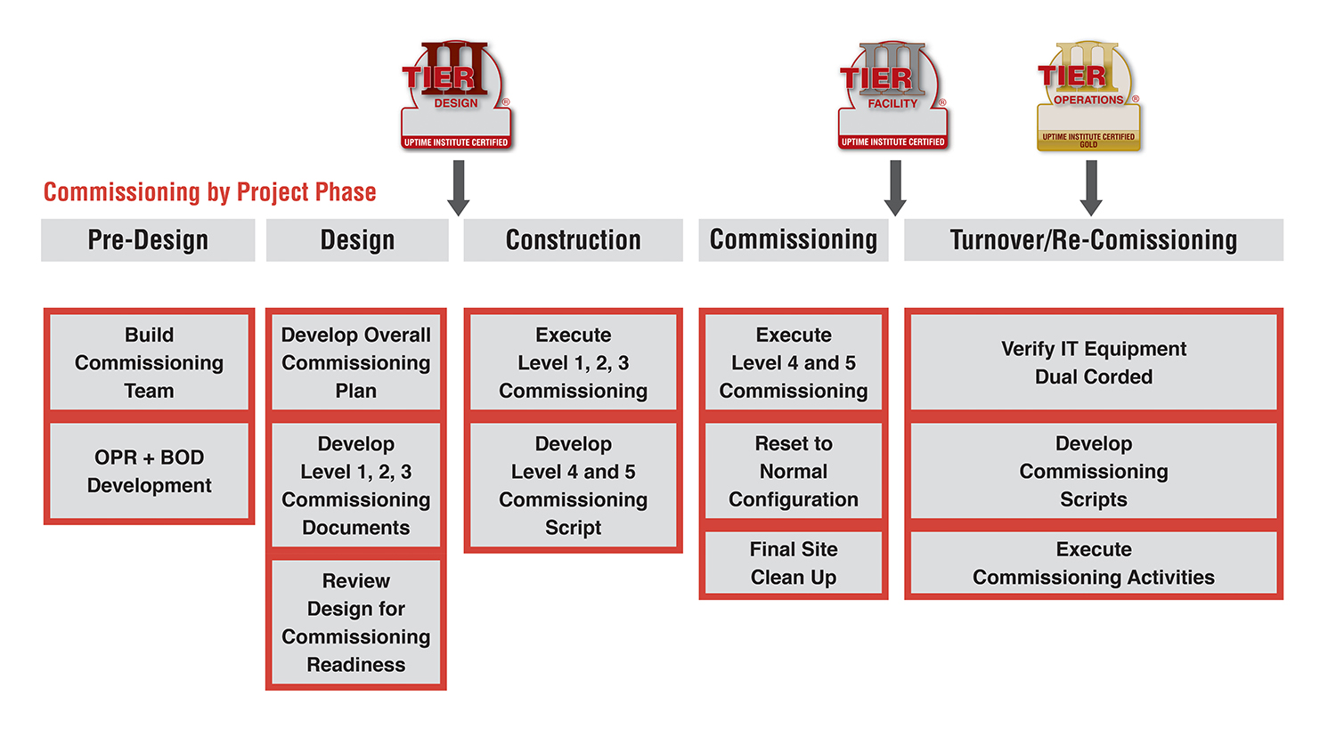
COMMISSIONING LEVELS
Over time, various organizations have defined the levels of commissioning. As a result, a data center owner may encounter a number of variations when attempting to understand and implement a commissioning program. With this publication, Uptime Institute clarifies the purpose of each level. However, each and every data center project is unique, which could mean that one or more of these activities might fit better within a different level of commissioning for some projects. Table 1 is organized to outline the process and sequence for commissioning, but the most important thing is that all the activities are completed. The high reliability essential to mission critical facilities requires that a rigorous and complete commissioning program includes all five levels to ensure that capital investments are not wasted.
Table 1. Commissioning Levels 1-5
COMMISSIONING AND UPTIME INSTITUTE TIERS
Unlike Uptime Institute’s Operational Sustainability Standard, the rigor associated with commissioning a data center has little relationship to its Tier level. The scope for commissioning and testing a Tier I data center may be less than that of a Tier IV data center—based on differences in the actual design complexity, topology, size, components, and sequence of operations. However, the roles and responsibilities and technical requirements for the commissioning team should not differ largely between Tiers and should be just as rigorous and comprehensive for a Tier I as it would be for a Tier IV.
COMMISSIONING STAKEHOLDERS
The most critical stakeholders involved on any project are listed below. They should fulfill their major roles sequentially. Stakeholders with additional expertise or valuable contributions should also participate. The CxA should ensure that the roles and responsibilities of the commissioning stakeholders are balanced and well documented.
Owner: The owner should initiate the commissioning process at the project outset, including identifying key stakeholders to take part in the program and communicating expectations for the commissioning program. Owner’s personnel are typically responsible for internal engineering, project management, and administration; however, the IT end user may also be part of the owner’s team. When the owner’s personnel lack the necessary experience for these activities, those responsibilities should be delegated to an authorized third-party representative, typically referred to as an owner’s representative. If the owner does not participate (or appoint a representative), no one on the commissioning team will have the knowledge or perspective to represent the owner’s interests. The end result could be a sub-standard facility, unnecessarily vulnerable to outages and unable to support the business needs.
Contractor: The commissioning team always includes the general contractor and specialty trade contractors, including mechanical, electrical, and controls, as well as OEM vendors who will be bringing equipment on site and assisting with testing. Without contractors, commissioning activities will be nearly impossible to complete properly. Contractors often coordinate vendors and physically operate equipment during commissioning procedures. Uptime Institute experience indicates that although contractors are rarely excluded entirely from commissioning their input is sometimes undervalued.
Architect and engineers: The Engineers-of-Record are legally responsible for the design of the data center, including those responsible for mechanical and electrical systems. Design intent may be compromised if designers do not participate in commissioning. The design engineer specifies the sequence of operations and is the only party who can confirm that the intent of the design was met.
Operations: The maintenance and operations managers, supervisors, and technicians are ultimately responsible for the day-to-day operations of the data center and its maintenance activities. This group may include owner’s personnelor a third party contracted for ongoing operations. Excluding Operations is a huge missed opportunity for training and compromises the team’s ability to verify maintenance and operations procedures (SOPs, EOPs, MOPs, etc.). Without live training during commissioning to verify effective procedures, the operations team will not be fully ready for maintenance or failures when the facility is in operation.
CxA: Ideally a third party is the responsible authority for the planning and execution of the entire commissioning process. The CxA may be an owner’s representative or a qualified mechanical or electrical contractor. Trying to commission without a CxA could result in poorly planned, undocumented, and unscripted commissioning activities. Additionally, it makes it more difficult to close out construction and properly transition to operations, which includes proper punch-list item closeout and execution of training for operations staff.
PRE-DESIGN PHASE ELEMENTS AND BENCHMARKS
Pre-design phase commissioning immediately follows the approval of a data center project and begins with selection of the CxA through a request for proposal (RFP) process (see Table 2). During the pre-design phase the owner, Engineers-of-Record, operations staff, and the CxA identify the owner’s project requirements (OPR) for the data center. Table 2 lists each participant in data center design, construction, and commissioning and denotes responsibility for particular tasks. In some projects, the owner may elect to utilize an owner’s representative to manage the day-to-day activities of the project on their behalf.
Table 2. Pre-Design Phase tasks
At this time, the owner should hire the data center facility manager and one data center facility supervisor to support the commissioning activities as representation for the operations team. It is not necessary to build the entire operations team to support the commissioning and construction activities.
PRE-DESIGN PHASE COMMISSIONING TECHNICAL REQUIREMENTS
Tasks to complete during the pre-design phase include developing a project schedule that includes commissioning, creating a budget, outlining a commissioning plan, and documenting the OPR and basis of design (BOD).
Technical requirements during this phase include:
CxA Selection
Selecting the CxA in the Pre-Design phase allows it to help develop the OPR and BOD, the commissioning program, the budget, and schedule.
The CxA should have and provide:
• Appropriate staff to support the technical requirements of the project
• Experience with mission critical/data center facility commissioning
• Experience with the project’s known topologies and technologies
• Sample commissioning documents (e.g., Commissioning Plan, Method Statements, Commissioning Scripts, System Manual)
• Commissioning certifications
• Client referrals
The CxA should be:
• Contracted directly to the owner to ensure the owner’s interests are held primary
• Optimally aligned to both the owner’s operations team and the owner’s design and construction team to further align interests and gain efficiencies in coordinating activities throughout commissioning
• An independent third party
Ideally, the CxA should not be an employee of the construction contractors or architect/engineering firms. When a third-party CxA is not a viable choice, the best alternative would be a representative from the owner’s team when the technical expertise is available within the company. When the owner’s team does not have the technical expertise required, a third-party mechanical or electrical contractor with commissioning experience could be utilized. Of course, cost is a factor in selecting a CxA, but it should not be allowed to compromise quality and rigor.
Project Schedule
• Must include all commissioning activity time on the schedule to avoid project delays.
• Should allot sufficient time for correcting installation and performance deficiencies revealed during commissioning.
• Should assess the requirement and/or capability for post-occupancy commissioning activities. This can include provisions for seasonal commissioning to assess the performance of critical components in a variety of ambient conditions.
At this point, the schedule should have significant flexibility and can be better defined at each phase. Depending on the size, complexity, and sequence of operations associated with a facility, a rigorous Level 5 commissioning schedule could take up to 20 working days or longer. Even for small and relatively basic data centers, commissioning teams will find it challenging to complete Level 5 commissioning with a high level of detail and rigor in less than a few days.
Commissioning Budget
• Should include a large contingency reserve for Level 4 and Level 5 commissioning budgets
• Should include all items and personnel required to support complete commissioning
At this point in the process there are a considerable number of unknowns in the design, construction, and commissioning requirements. Budgets for Level 4 and Level 5 commissioning should include a large contingency reserve to accommodate the unknown parameters of the project. This contingency reserve can be reduced as appropriate as the project moves along and more and more items are defined. However, the final budget should still have a contingency reserve to account for unforeseeable issues, such as additional load bank rental time in the event commissioning takes longer than scheduled. Budgets need to include all items and personnel required to support commissioning. This includes, but is not limited to, load banks, calibrated measurement devices, data loggers, technician support, engineering support, and consumables such as fuel for engine-generator sets.
OPR and BOD
American Society of Heating, Refrigerating and Air-Conditioning Engineers, Inc. (ASHRAE) Standard 202 defines an OPR as “a written document that details the requirements of a project and the expectations of how it will be used and operated. This includes project goals, measurable performance criteria, cost considerations, benchmarks, success criteria, and supporting information. (The term Project Intent or Design Intent is used by some owners for their Commissioning Process Owner’s Project Requirements.)”
ASHRAE Standard 202 defines a BOD as “a document that records the concepts, calculations, decisions, and product selections used to meet the OPR and to satisfy applicable regulatory requirements, standards, and guidelines. This includes both narrative descriptions and lists of individual items that support the design process.”
The OPR and BOD are generated by the project owner and communicate important expectations for the data center project. These documents should be revised and updated at the end of each phase in the construction process. Specific to data center commissioning, the OPR and BOD should:
• Comply with ASHRAE Standard 202, or similar
• Specify that the CxA is responsible for all commissioning, testing, and formal reporting
• Identify whether the intent of the data center design is to be scalable with IT requirements and whether the use of shared infrastructure is allowed and note any subsequent design features necessary to commissioning
The decision as to whether or not the design intent is to be scalable or use shared infrastructure will have a large effect on subsequent implementation and commissioning phases. Shared infrastructure systems in an incremental buildout can potentially increase the risk associated with future commissioning phases. Careful planning can mitigate this risk. Where shared infrastructure is to be used in a phased implementation, the OPR or BOD should highlight the importance of including design features that will allow a full and rigorous commissioning process at each phase of project implementation.
DESIGN AND PRE-CONSTRUCTION PHASE ELEMENTS AND BENCHMARKS
The design and pre-construction phases are commonly blended into a design/build format in which some activities are completed concurrently (see Table 3). The design typically goes through multiple iterations between the Engineer-of-Record and owner; each iteration identifies additional data center design details. Since the Engineer-of-Record is responsible for creating the designs and ensuring their concurrence with applicable commissioning documents, it becomes the responsibility of the other stakeholders to verify compliance. The CxA and contractor should review the design throughout this process, provide feedback based on their experience, and ensure compliance with the OPR document.
Table 3. Design and Pre-Construction Phase tasks
DESIGN AND PRE-CONSTRUCTION PHASE COMMISSIONING TECHNICAL REQUIREMENTS
Commissioning Plan
The commissioning plan is the heart of the commissioning program for a data center. While the CxA will take the lead in its development, all other stakeholders should review and participate in the approval of the final commissioning plan. Utilizing each unique skillset in developing and reviewing the commissioning program will help ensure a rigorous commissioning program.
Once appointed, the CxA must develop the overall commissioning plan, which generally includes:
• Scope of commissioning activities, including identification of any re-commissioning requirements
• General schedule of commissioning
• Documentation requirements
• Risk identification and mitigation plans
• Required resources (e.g., tools, personnel, equipment)
• Identification of the means and methods for testing
Design Review
• For concurrence with the OPR and planned operations
• For commissioning readiness
At this phase, appropriate stakeholders should develop plans, checklists, and reports for Level 1, Level 2, and Level 3. All stakeholders must review these documents. Additional technical requirements during this phase include:
• Review project schedule and budget to ensure the schedule continues to maintain adequate resources and time to complete commissioning
• Verify adherence to OPR and BOD
• Amend documents as necessary in order to keep them up to date
• Add design elements as required to allow for the commissioning program to meet the minimum OPR and meet commissioning readiness requirements
• If the design is scalable and to be implemented in future phases with shared systems, ensure that the design allows for future commissioning by including enhancements to reduce the risk to the active IT equipment.
• Ensure that equipment specifications identify that the specified capacity is net of any deductions or tolerances allowed by national or international manufacturing standards (verified during Level 1 and Level 3)
Typically, long-lead items are procured using an RFP process in parallel with the design process. The commissioning requirements for this equipment should be included in the RFP documents and adherence to these should be assessed throughout the equipment delivery and installation. As part of these requirements, RFPs should identify the requirement for on-site OEM technician support throughout Level 4 and Level 5.
Commissioning Plans and Scripts for Level 1, Level 2, and Level 3
• OEMs should provide the written test procedure to the commissioning team for approval prior to the Level 1 activities.
• Contractors, in conjunction with the CxA, should provide Level 2 Post-Installation checklists from the record drawings to verify installation of all equipment.
• The entire commissioning team should review all Level 2 checklists.
• OEMs, in conjunction with the CxA, should provide start-up and functional checklists for Level 3.
• Where component-level functional testing is necessary beyond the OEM’s typical scope of work, the
CxA shall create testing procedures that should be reviewed by the commissioning team and executed by
the contractors.
CONSTRUCTION PHASE ELEMENTS AND BENCHMARKS
Throughout the data center construction, the CxA will monitor progress to ensure that the installations conform to the OPR document. Additionally, the first three levels of commissioning will take place and be overseen by the CxA (see Table 4).
Table 4. Construction Phase tasks
CONSTRUCTION PHASE COMMISSIONING TECHNICAL REQUIREMENTS
During the construction phase, the focus moves from developing plans to execution, with team members executing Level 1, Level 2, and Level 3 activities. At the same time, the operations team and the CxA develop scripts for Level 4 and Level 5, which are to be reviewed by all stakeholders.
Technical requirements during this phase include:
• Review project schedule and budget to ensure the schedule continues to have adequate time and budget to
complete commissioning
• Protect equipment stored on site awaiting installation from hazards (e.g., dirt and construction debris,
impact, fire hazards) and maintain according to manufacturer’s recommendations
• Verify that circuit breakers are set in accordance with the short circuit and breaker coordination and arc
flash study
• Repeat Level 1 procedures in the actual data center environment since factory witness testing is
performed in ideal conditions rarely seen in practice in the data center, ensuring that no equipment
damage occurred during transit and that the equipment performs at the same level as when it was tested
at the factory
• Ensure that the building management system (BMS) functions at a basic level so that it is ready to
support critical Level 4 and Level 5 commissioning activities
• Log critical asset information (e.g., make, model, serial number) into the maintenance management
system (MMS) (or other suitable recordkeeping) as equipment is received on site to be available for the
operations team
• Continue to submit formal reports to the owner detailing all items tested, steps taken to test, and the
results as soon as reasonably possible
• Repeat entire testing procedures when programming or control wiring is altered to correct a testing step
that does not complete successfully as it is possible to have an unexpected impact
In addition, Engineers-of-Record should provide a finalized sequence of operations document to the CxA, so it can create the Level 4 and Level 5 commissioning scripts.
Commissioning Plans and Scripts for Level 4 and Level 5
Script development is the responsibility of the CxA, with support from all other team members.
Plans and scripts should:
• Identify every test and step to be taken to complete commissioning
• Identify and describe the anticipated results for each step of the test
• Identify responsible parties for each step of each test to ensure that everyone is available and
prepared, and to assist with schedule and budget reviews
• Identify safety precautions and personal protection equipment (PPE) requirements for all team members
Testing should be conducted:
• Under expected normal operations in the same manner that the operations team will operate the
data center
• Under expected maintenance conditions in the same manner that the operations team will maintain
the data center
• In manual operation as necessary to support future upgrades and replacements
In addition, commissioning should simulate system and component failures to test fault tolerant features, even when fault tolerance may not be a specific design assumption because it will inform the operations team on how the infrastructure responds when failures inevitably occur. Uptime Institute recommends testing in as many additional scenarios as possible that make sense for the design—even scenarios that may be outside the scope of design—to provide key information to operations about how to respond when the facility does not function and/or respond as designed.
LEVEL 4 AND 5 COMMISSIONING PHASE ELEMENTS AND BENCHMARKS
Once construction of the data center has been substantially completed, the CxA will lead the team through Levels 4 and 5 commissioning. The purpose of these activities is to ensure that individual systems and the full data center ecosystem function as they were intended in the design and OPR documents. This includes verifying requiredcapacities and ensuring that equipment can be isolated as intended and that the data center responds as expected to faults (see Table 5).
Table 5. Commissioning Phase tasks
While weather cannot be anticipated, it can and will have an impact on the final commissioning results. Results from Level 4 and 5 commissioning activities should be extrapolated to predict how the equipment would perform at the actual design extreme temperatures and conditions. However, commissioning activities should be scheduled seasonally to verify system operation for the actual extreme and varying ambient conditions for which it was designed—especially in the event economizers are utilized in the data center.
LEVEL 4 and 5 COMMISSIONING PHASE TECHNICAL REQUIREMENTS
Level 4 and 5 commissioning presents a unique opportunity to any data center, which is to be able to fully test and practice equipment operation in any building condition without any risk to critical IT load. Improvements in future operations can result when stakeholders take advantage of this opportunity.
All critical components and systems must be fully tested—representative testing should not be acceptable for mission critical data centers.
Level 4
• Level 4 must include load bank tests of the engine-generator sets, UPS, and UPS battery systems at design
and rated capacities.
• Minimum continuous runtime durations of not less than eight hours are recommended for all load bank
tests; however, continuous runtimes of up to 24 hours are considered a best practice.
• Ensure that load banks are distributed within critical areas to best simulate the actual IT environment
distribution, ideally physically located within racks and with forced cooling on a horizontal path, which
allows for more accurate and realistic mechanical system testing.
• Prior to commencing Level 5, building management and control system (BMCS) graphics should be
completed to support the commissioning activities and to help commission the BMCS because operations
staff will eventually rely on the BMCS including alarming and data trending features.
Level 5
• Ensure that commissioning team members and contractors are positioned strategically throughout the
data center to monitor all systems throughout Level 5
• Size load banks as small as reasonably possible for Level 5 activities to best simulate the
actual IT environment for more accurate and realistic mechanical system testing
• Perform Level 5 tests with the fire detection and suppression systems active, rather than in bypass to
ensure there is no adverse impact to the critical infrastructure
• Isolate equipment at the upstream circuit breaker when performing equipment isolations to simulate
maintenance activities rather than at the local disconnect physically located on the unit
• Complete evaluations when changes are made throughout Level 5 to fix deficiencies and determine
which, if any, tests must be repeated/redone
• Consider the need to retest more than once in order to ensure the successful test was not an anomaly
when an initial test is not successfully completed
• Complete testing on both utility power and on engine-generator power (or other alternative to utility
power source)
• When simulating faults, simulate multiple fault types across separate tests on each piece of equipment
• Ensure that sensor failures are included in the testing scope when simulating faults on highly automated
data centers that rely heavily upon field sensors
• Document, identify, and validate normal operating set points, alarms, and component settings
• Monitor alarms that are generated in the BMCS and electrical power monitoring system (EPMS) to
ensure that they are accurate and useful
• At a minimum, take electrical load and critical area temperature readings between each discrete test;
where data loggers are used, measurements should be logged every 30-60 seconds
• Test a variety of load conditions—25%, 50%, 75%, and 100% step loads—in order to simulate the actual
load conditions as a data center gradually increases its critical IT load
• Test (as possible without causing damage) emergency conditions—such as N-1 and no cooling with
design load—to provide the information necessary for the operations team to structure future
emergency operating practices and plan for staff appropriately
• Install aisle containment strategies that are to be utilized as part of the design to ensure the aisle
containment strategies support the infrastructure as required
Site Cleanup
• Replace the air filters for the electrical systems and heating, ventilation, and air conditioning (HVAC)
systems following the conclusion of Level 5 commissioning
• Flush and clean piping and ductwork to ensure construction debris does not impact future mechanical
plant performance
TURNOVER-TO-OPERATIONS PHASE ELEMENTS AND BENCHMARKS
The turnover-to-operations includes all activities associated with formally turning the facility over to the owner and Operations. Primarily, this includes completing the final documentation associated from the commissioning activities Levels 1-5 and utilizing the commissioning results to finalize SOPs, MOPs, and EOPs.
Needless to say, this is a critical juncture for the data center. Soon after Level 4 and 5, the facility will become live and support critical IT infrastructure, which begins the need to maintain the facility. At this time, Operations must take all of the lessons learned and knowledge gained from the construction and commissioning phases to finalize the maintenance and operations program. Operations must complete this work in a relatively short amount of time in order to minimize risk to the data center. The longer it takes to finalize all of the documentation and processes, the longer the facility will be at risk. Operations needs full support during this transition to ensure the overall uptime and success of the data center.
During the Turnover-to-Operations phase, the CxA duties can include:
• Ensuring that all post-Level 5 punchlist items are successfully completed and closed out
• Facilitating and/or coordinating infrastructure or OEM training to the operations staff
• Assisting as necessary the development of critical operating procedures.
The CxA is also responsible for gathering all testing reports and checklists from all five levels of commissioning to create the final commissioning report. The final report to the owner should include:
• Electrical and mechanical load and system condition readings taken at timely intervals before major
actions are implemented in each test
• All steps, results, and system readings at every stage of the commissioning
The CxA should return to the site approximately one year following completion of commissioning to review the building operations and to ensure there are no outstanding items related to re-commissioning or seasonal commissioning efforts.
RE-COMMISSIONING AND FUTURE INSTALLATION PHASE ELEMENTS AND BENCHMARKS
Commissioning should be performed any time new infrastructure is installed or any time there is a significant change to the configuration of existing infrastructure. This could include planned expansion of the data center or major replacements (see Table 6).
Table 6. Re-Commissioning Phase tasks
In data centers that are built to be scalable, it is imperative that commissioning be just as rigorous for the follow-on infrastructure deployments to minimize risk to the facility. Commissioning activities undoubtedly add risk to the data center, especially where infrastructure systems are shared. However, this risk must be weighed against the risk of performing the associated commissioning tests. If a component or system is not going to perform as expected, the owner must decide if it is better to have this occur during a planned commissioning activity or during an unplanned failure. While performing a rigorous commissioning program during the initial buildout may prove the concept of the design, the facility could potentially be at risk if all of the new infrastructure components and systems are not tested rigorously.
These types of commissioning activities, by their very nature, occur while the systems are supporting critical IT load. In these instances, the operations team best knows how these activities may impact that mission critical load. During re-commissioning or incremental commissioning, the operations team should be working in very close collaboration with the commissioning team to ensure the integrity of the data center. Additionally, if re-commissioning involves changes to the configuration of the data center, Operations needs full awareness so that operating procedures that impact maintenance and emergency activities can be updated and tested completely.
The best way to mitigate the risk of re-commissioning efforts or for follow-on phases is to ensure that the facility is properly and extensively commissioned when it is originally built. And, as part of a rigorous re-commissioning program, all of the points discussed in this paper for standard commissioning apply to the re-commissioning efforts. However, due to the higher level of risk with these activities, there are some additional requirements.
RE-COMMISSIONING AND FUTURE INSTALLATION PHASE TECHNICAL REQUIREMENTS
All of the technical requirements previously provided apply to re-commissioning and future installation phases. However, follow-up commissioning activities also require the following special considerations by the CxA:
• Adequate notice must be provided to service owners about the schedule, duration, risk, and
countermeasures in place for the re-commissioning activities in order to gain concurrence from IT
end users.
• For facilities that are based on a dual-corded IT equipment topology, the owner and Operations
should verify that the existing critical load is appropriately dual corded where systems that support
installed IT loads are to be commissioned.
• As load banks can introduce contaminates, load bank placement should be considered carefully so as not
to impact the existing critical IT equipment.
• Detailed commissioning scripts must be prepared and followed during commissioning to ensure minimal
risk to existing IT equipment. Priority should be given to the live production IT environment, and back-out
procedures should be in place to ensure an optimal mean time to recovery (MTTR) in case of a power
down event.
• Seasonal testing of the systems should be performed to verify performance in a variety of climatic
conditions, including extreme ambient conditions. This also ensures that economizers, where used, will
be tested properly.
CONCLUSION
Commissioning activities represent a unique opportunity for data center owners. The ability to rigorously test the capabilities of the critical infrastructure that support the data center without any risk to mission critical IT loads is an opportunity that should be capitalized on to the maximum possible extent. Uptime Institute observes that this critical opportunity is being wasted far too often in data center facilities, with not nearly enough emphasis on the rigor and depth of the commissioning program required for a mission critical facility until critical IT hardware is already connected.
A well-planned and executed commissioning program will help validate the capital investment in the facility to date. It will also put the operations team in a far better position to manage and operate the critical infrastructure for the rest of the data center’s useful life, and ultimately ensure that the facility realizes its full potential.
Ryan Orr
Ryan Orr joined Uptime Institute in 2012 and currently serves as a senior consultant. He performs Design and Constructed Facility Certifications, Operational Sustainability Certifications, and customized Design and Operations Consulting and Workshops. Mr. Orr’s work in critical facilities includes responsibilities ranging from project engineer on major upgrades for legacy enterprise data centers, space planning for the design and construction of multiple new data center builds, and data center Maintenance and Operations support.
Chris Brown
Christopher Brown joined Uptime Institute in 2010 and currently serves as Vice President, Global Standards and is the Global Tier Authority. He manages the technical standards for which Uptime Institute delivers services and ensures the technical delivery staff is properly trained and prepared to deliver the services. Mr. Brown continues to actively participate in the technical services delivery including Tier Certifications, site infrastructure audits, and custom strategic-level consulting engagements.
Ed Rafter
Edward P. Rafter has been a consultant to Uptime Institute Professional Services (ComputerSite Engineering) since 1999 and assumed a full-time position with Uptime Institute in 2013 as principal of Education and Training. He currently serves as vice president-Technology. Mr. Rafter is responsible for the daily management and direction of the professional education staff to deliver all Uptime Institute training services. This includes managing the activities of the faculty/staff delivering the Accredited Tier Designer (ATD) and Accredited Tier Specialist (ATS) programs, and any other courses to be developed and delivered by Uptime Institute.
Case Study: Italy’s First Tier IV TCCF
/in Design/by Kevin HeslinSystem efficiency proves more important than equipment efficiency
By Paolo Barberis, Leonardo Sergardi, and Ferdinando Ciardullo
FastWeb is an Italian telecommunications operator, 100% owned by Swisscom, providing ultrabroadband services to the Italian consumer and corporate markets, in which it holds a 35% market share. Since its founding 15 years ago, FastWeb has invested in infrastructure. For instance FastWeb has an optical fiber network of about 38,000 kilometers. This strategy was reconfirmed for 2014/2015 when FastWeb announced its Fiber to the Street project (FTTS), a two-year plan to provide ultrabroadband services to 30% of the Italian population, an increase from 20%. Similarly, FastWeb has invested in data centers. At present, the company owns two data centers, with a total area of 6,000 square meters (m2) of white space. Today FastWeb has chosen to focus on providing network services and services such as housing, hosting, Cloud, managed services, and managed security.
In order to support these services, FastWeb decided to build a new data center offering the highest level of security possible to its clients. This goal led to the decision to achieve Italy’s first Tier IV Certification of Constructed Facilities (TCCF) with quality construction and energy efficiency also in mind. After examining the various options, FastWeb decided to site the data center within an owned, existing facility built in 1937.
FastWeb’s choice to build its new data center within its headquarters alongside the existing data rooms and offices was the main constraint in developing the project. As a result the design approach was reversed. Every effort was made to build the best infrastructure possible to meet FastWeb’s performance requirements, without disrupting the existing functions and the surrounding environment. In practice, it was necessary to identify the parts of FastWeb’s entire business plan that could be carried out on site optimally and conform to the plan itself.
During the preliminary design phases, a major effort was made to locate the optimal solution, which made it possible to develop the project details in a very short time, with- out requiring any changes to the drawings. The challenge was integrating and holistically adapting the spaces available to the space requirements of the white space and sup- porting equipment, the volumetric plan of the facility, the requirements of Tier IV, and the efficiency goals. As a result of the detailed preliminary planning, time was recovered during the detailed design and execution phases, which had practically no surprises.
Finally, the acoustic pollution needed to be managed in line with the local standards because of the downtown location of the site. FastWeb carried out an acoustic audit to identify any mitigation measures that would be needed. On the basis of the results the mitigation interventions were decided. Acoustics were tested twice afterwards: once during commissioning and then again after the data center went live. The issue of acoustic pollution was fully addressed by specifying super-silenced chillers and engine-generator sets and positioning them in the courtyard and installing appropriate gear to make them super silent. These steps did not affect the loads in any way.
Because the site was already part of FastWeb’s network, the new data center ben- efits from all the robustness and redundancy of connectivity of the network at low cost. In addition, the company’s Technological Department is located on the site, which gives the facility access to the highest technical skills available. Moreover, from a market viewpoint, key clients like being hosted in central Milano, which is a capital of finance and industry and near many of their headquarters.
Figure 1. Data room layout
Figure 2. Mechanical plant infrastructure in the internal courtyard
The facility comprises a 600-m2 data room with 80 m2 of ancillary space, 930 m2 of machine rooms, and 650 m2 of external technological areas, all located in the same building on multiple adjacent floors (see Figures 1 and 2). The facility’s white space houses (162) 42U racks using Hot Aisle containment technology (see Figure 3), with 1,250 kilowatts (kW) available for IT loads (an average of 7.5 kW/rack and power density of 2.1 kW/m2). The facility can also accommodate a few high-density (20 kW/rack) islands. The data center is the first one built in Italy to achieve TCCF from Uptime Institute.
Figure 3. Data room Cold Aisle
FastWeb’s data center includes a double-path, always-on scheme, both for electric
as well as mechanical systems, including two feeds from the external utility. Utility service to the facility is 5 megavolt-amperes (MVA), with two 2.4 megawatt (MW) engine-generator sets (N+N) (continuous-rated power as per ISO 8528) and four very high yield, scalable modular static 800 kVA UPSs (N+N),capable of operating in voltage double conversion, line interactive, or off-line modes to limit losses, producing annual efficiencies of 98% (see Figure 4). Total cooling capacity is 3.340 kW.
Figure 4. UPS room
PUE as measured during commissioning was 1.25. The FastWeb facility includes both a building management system (BMS) (see Figure 5) and Schneider Electric’s StruxureWare Data Center Infrastructure Management (DCIM) that help it manage energy use and achieve its energy goals. Together these monitor or control about 10,000 points and variables.
Figure 5. BMS control panel
In order to ensure the most rapid and easiest flexibility of change, power distribution and data cabling have been made on site above the racks. Power is distributed through double-path busbars. Power to the racks can be completely changed without affecting the others, because feeds from the busbar are through extractable boxes equipped with switches. This system has eliminated the need for electric distribution panels bringing a noticeable reduction of losses related to electrical distribution.
The data center required about 50,000 m of power cables and about 50,000 m of auxiliary and control cables plus 900 manual and automatic valves on the cooling circuits. Two distinct 40 Gbit fiberoptic backbones link the facility to the external mains network.
COOLING
In order to reach FastWeb’s high energy efficiency goals, the cooling system
has been designed to reduce the energy required for pumps as allowed by the existing building. The mechanical systems are sized to ensure the data room has a C1 class microclimate, as defined by ASHRAE’s Thermal Guidelines. Design temperatures at the server input are 77°F (25°C), which can be raised to 86°F (30°C) in case of future installation of new-generation servers.
The choice of cooling equipment was made with overall facility efficiency in mind, considering the real operational parameters of the system (temperatures, loads,
etc.) and the specific designed setting logic. In other words, simply picking the most efficient equipment does not guarantee the most efficient system. This thinking led to solutions where the highest efficiency equipment was not chosen for the project.
It was gratifying then when operating experience confirmed that most efficient system was achieved by matching the main equipment to the specific operating conditions expected in the facility. This outcome was particularly noticeable in the performance of chiller units and in-row units.
Four high-efficiency chillers provide N+N cooling to the facility. The chillers are leading edge in terms of energy efficiency, internal redundancy, reliability, occupancy and noise; they are equipped with oil-free magnetic levitation compressors and are specified to be super silenced. Both primary cooling loops are equipped with inertial refrigerated water storage tanks to ensure operation of the data room for 15 minutes in case of blackout. Secondary distribution of cooling fluids is achieved using double-ring distributions, each powered by one of the two chiller plants. The energy efficiency ratio (EER) coefficient of 9.0 (50% of rated load for each chiller) demonstrates the energy efficiency of the system.
A dedicated control system ensured that the chillers operate as efficiently as possible, balancing their output ac- cording to the load present. The same system also identifies maintenance actions—in addition to routine maintenance operations—that could improve efficiency.
In the white space, in-row cooling units ensure an N+N redundancy factor for each aisle. During normal operation, each aisle is cooled separately thanks to modulating two-way valves and fans activated by inverters.
The in-row technology was chosen since it has the following advantages respect to the traditional perimeter computer room air handlers CRAH units:
The high temperature of the chilled water (15–20°C) used in the facility means that air can’t be dehumidified in the summer. As a result, the facility includes two direct expansion generator sets operating with heat pumps to treat the fresh air. Two cascaded heat recovery systems give the units particularly high overall efficiency.
FastWeb utilizes a DCIM system (see Figure 6) and a double-path BMS to control the facility , which accounts for energy use to the PDUs and to the in-row cooling units.
Figure 6. Data room BMS – DCIM control panel
The BMS and DCIM integrate control of the facility and the IT infrastructure, correctly managing in real time the operating variations of the servers due to the use of cloud tools as well as those due to changes and hardware and software physical integrations. The DCIM system has been equipped with specific modules dedicated to the management of colocation facilities with various users and companies present in the same room.
FIRE PREVENTION
Fire prevention in the facility is particularly advanced. The entire system combines a traditional smoke detection system, combined with a high-sensitivity smoke detection system (HSSD) for early detection. An inert gas IG01 (argon) system can be deployed for active fire protection. The system is centralized with a double set of cylinders (main and reserve), to protect the data room, the tape library, UPS rooms, batteries, electric transformers, and the engine generators.
FINAL RESULT
Design work proceeded through the following phases:
• Site assessment
• First preliminary stage
• Second preliminary stage in which FastWeb’s needs were matched to the features of the site
• Detailed design, with a high level of definition (see Figure 7)
All the phases included cost estimates, timing, and impact on the existing facilities.
Figure 7. Deployment phases and process model
The whole design and construction process (from kick off to commissioning) required a high level of communication between all the people involved in project implementation, with continuous sharing of choices, decisions, and changes in order to achieve the owner’s desired goals. In addition, each phase of design was developed to the greatest degree compatible with that given phase. Creating detailed drawings and documents reduced miscommunication and confusion on the project.
A team comprising FastWeb stakeholders, including the project leader, IT, networking, business unit, operation, facility, maintenance, purchasing managers, as well as design engineers and the director of works managed the design, procurement, and construction processes. The team, through meetings held at least weekly, constantly checked and managed the whole construction process, sharing and reporting results and decisions at
the end of each phase to the board of directors. Additional communication took place at all critical moments of the process. This team approach ensured that the construction would meet budgets (with a 5% tolerance) and deadlines, while providing a facility that meets FastWeb’s needs.
Paolo Barberis
Paolo Barberis is the manager of the Department of Technology at FastWeb S.p.a., a telecommunications company operating landline and mobile networks in Italy. He graduated in electronic engineering in 1989 at the Politecnico of Milano and is a member of the Charter of Engineers of the Province of Sondrio. Mr. Barberis has over 25 years of experience in designing and managing Telecommunication and Information Technology services with landline and mobile operators having mission critical services. He has been entrusted with the design, construction, and management of six data centers.
Leonardo Sergardi
Leonardo Sergardi is a partner and the cofounder of the engineering and design company AS ingg. He has a degree in Electrotechnical Engineering from the Politecnico di Milano in 1978. Mr. Sergardi is an Accredited Tier Designer, Certified Data Centre Professional, Certified Data Centre Energy Professional, and a member of the Charter of Engineers of the Province of Milano. He has completed more than 100 projects and 20 data centers, with more than 35 years experience designing systems and project management for advanced tertiary buildings, data centers, and mission critical facilities.
Ferdinando Ciardullo
Ferdinando Ciardullo works at the engineering and design company AS ingg. He has a degree in Mechnical Engineering at the Politecnico di Milano. Mr. Ciardullo is a CDCDP and a member of the Charter of Engineers of the Province of Milano. He has completed more than 100 projects and 15 data centers, with more than 35 years experience designing systems and project management for advanced tertiary buildings, data centers, and mission critical facilities.
Data center design goals and certification of proven achievement are not the same
/in Design, Executive, Operations/by Matt StansberryOn March 13, 2015, Data Center Knowledge published an article “ViaWest Accused of Misleading Customers in Las Vegas”. The following is excerpted from the article.
Uptime Institute does not comment on specific projects, as a matter of commitment to our clients and governing policies.
But following the publication of the Data Center Knowledge article, we have received numerous variations on the following questions, which warrant clarification:
How many Tier Certifications of Design Documents, Constructed Facility, and Operational Sustainability has Uptime Institute awarded?
Since 2009, Uptime Institute has awarded 545 Certifications in 68 countries.
How many conflicts have been experienced in applying the Tier or Operational Sustainability criteria in any countries?
Uptime Institute criteria remain widely applicable and have not experienced conflict with local codes or jurisdictions.
How common is it for a data center to have one Tier Certification level for Design Documents and another Tier Certification level for Constructed Facility?
It is highly irregular for the Tier Certification of Design Documents (TCDD) and Tier Certification of Constructed Facility (TCCF) of the same data center to be misaligned in terms of Certification level. This is also an incongruent use of the Certification process, which was developed to provide assurances throughout the project to deliver on a single objective.
Instances of misaligned Tier Certification of Design Documents and installed infrastructure (i.e., stranded, altered or false Design Certifications) have been recklessly misleading to the industry and compelled us to amend the terms and conditions of Tier Certification so that Design Certifications expire after two years.
If discrepancies between Design and Facility Certifications happen, what is the purpose of the Tier Certification of Design Documents?
Tier Certification of Design Documents was never intended to be standalone designation as the end-point. It is provisional in nature and intended as a checkpoint on the Tier Certification of Constructed Facility and Operational Sustainability path to message upper management that the project is progressing to the Tier performance objective defined for the specific site.
There are multiple reasons that an enterprise data center project may achieve Tier Certification of Design Documents and not achieve Tier Certification of Constructed Facility. Some of these reasons include projects delays, cancellations, re-scoping. However, these same reasons for an enterprise project do not apply to a commercial data center services market, in which Tier Certifications drive competitive differentiation and pricing advantages for those who have demonstrated the capability of their facility.
What is Uptime Institute doing to prevent misrepresentation in the market?
In response to the gaming of the Tier Certification process for marketing reasons and to differentiate the achievement of Facility Certification, Uptime Institute implemented on 1 January 2014 a 2-year expiry for Tier Certification of Design Documents, as well as revocation rights for cases of clear, willful, and unscrupulous misrepresentations.
For a full list the sites that allow us to disclose their Tier Certification achievement please see: https://uptimeinstitute.com/TierCertification.
Julian Kudritzki, Chief Operating Officer, Uptime Institute