McKesson Retrofits Economizers in Live DC Environment
Pharmaceutical installs economizers in a live site to improve energy efficiency
By Wayne Everett, Dean Scharffenberg, and Coleman Jones
McKesson Corporation, the oldest and largest health-care services company in the United States, plays an integral role in meeting the nation’s health-care needs. McKesson is the largest pharmaceutical distributor in North America, delivering one-third of all medications used in the U.S. and Canada every day. In addition, McKesson Technology Services provides 52% of U.S. hospitals with secure data storage. With revenues in excess of US$122 billion annually, McKesson ranks 15th on the Fortune 500 list.
The McKesson facility is a purpose-built data center originally constructed in 1985. It includes 34,000 square feet (ft2) of raised floor space on two floors; an IT load of 1,690 kilowatts (kW) occupies 69% of the raised floor. Until the retrofit, 30-ton direct expansion (DX) air-cooled air handling units (AHUs) provided cooling.
The addition of a 2,000-ft2 economizer on the first floor (see Figure 1) and a new penthouse structure (see Figure 2) to house an economizer on the second floor will reduce the data center’s cooling requirement drastically when ambient temperatures allow. Currently the outside air economizer is on line with a total savings of 550 kW.
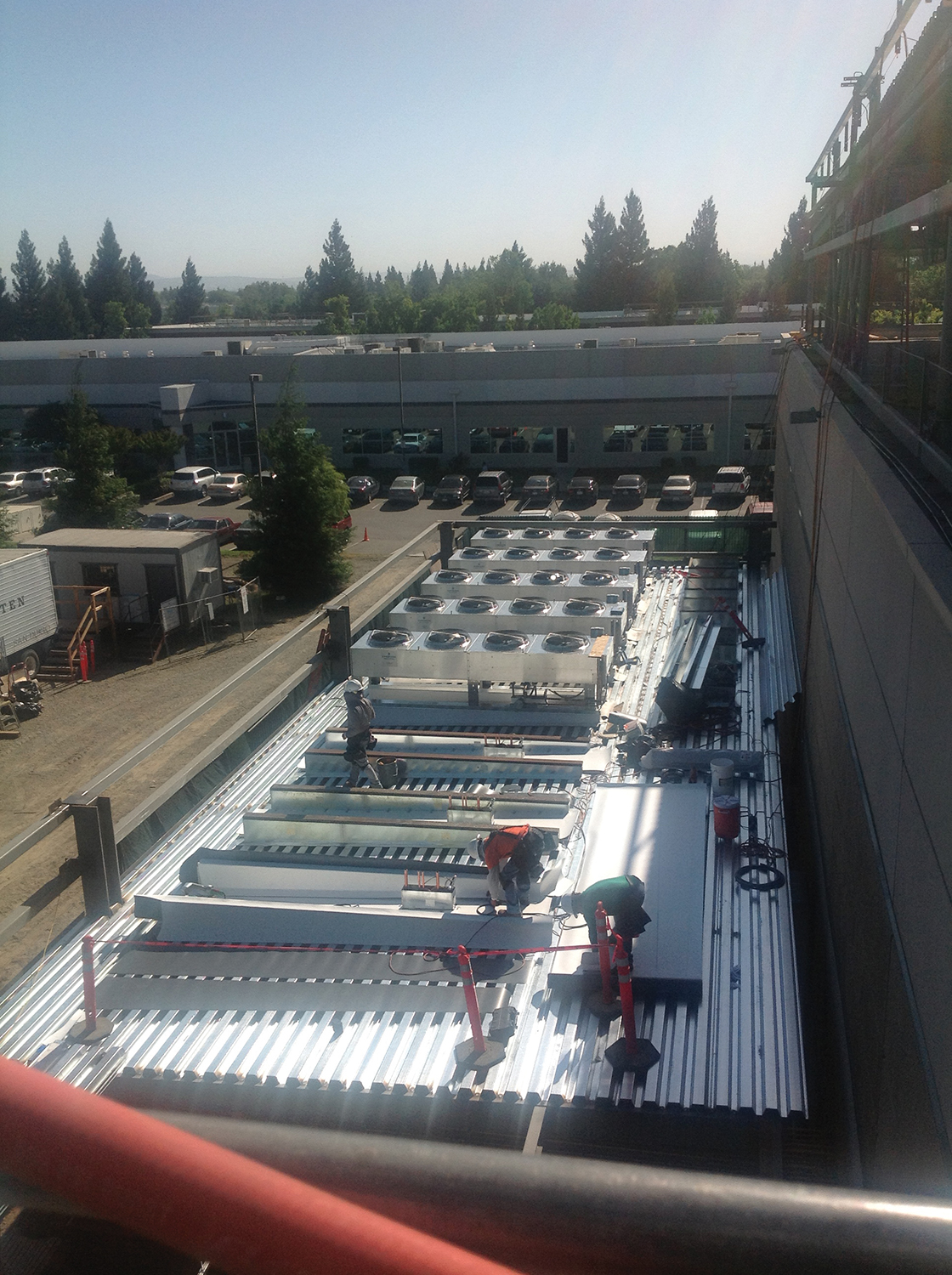
Figure 1. Roof deck of the first floor economizer
Being a leader in distribution and technology is achieved by continual improvement, something McKesson believes in and strives for. McKesson continuously strives to lower health-care costs for its customers. The goal of lowering costs while maintaining the best product for consumers was apparent in McKesson’s decision to retrofit its primary data center to use outside air for primary cooling.
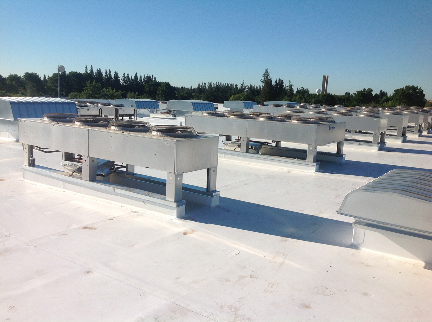
Figure 2. Roof of the completed penthouse.
The reason for retrofitting the facility was simple: McKesson wanted to use outside air in lieu of AHUs, thus reducing the power load. The construction plan was complex due to the strict zero downtime requirement of the fully operational facility. To ensure construction proceeded as planned, McKesson employed the expertise and experience of general contractor Rudolph and Sletten. The solution devised and implemented by McKesson and the Rudolph and Sletten team enables the McKesson facility to exhaust hot air from the Hot Aisles and introduce cool outside air under the raised floor. In addition, Rudolph and Sletten:
• Relocated the condensing units (CUs)
• Retrofitted existing AHUs
• Built the new first-floor economizer
• Installed controls and performed functional testing
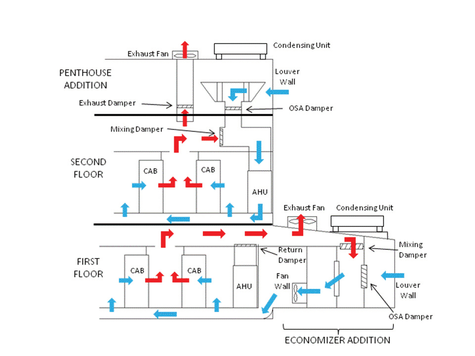
Figure 3. Airflow in McKesson’s data center
The design for introducing cool outside air into the first floor computer room removed 90 feet of the existing outside wall. Eleven condensing units populated a concrete pad on the other side of this wall. A new 2000 ft2 economizer room was constructed on this pad, and the condensing units (CU) were relocated to the roof of this new economizer room.
The economizer room consists of a warm air upper plenum area where the Hot Aisle plenum from the computer room is joined. A dozen exhaust fans penetrating the economizer roof expel warm air from the plenum area. Cool outside air is drawn through a louvered wall into a filter bank and a fan wall consisting of 17 variable speed fans. The fans blow air under the raised floor into the Cold Aisles. Nine mixing dampers between the warm air plenum and the nine outside air intake dampers allow for warming of cold outside air. The AHUs in the first floor room are not running when outside air is being cooled. Each AHU has a return damper that closes to preclude backflow through the AHU when outside air is in cooling mode (see Figure 3).
The design for introducing cool outside air to the second floor called for air to be ducted from a new penthouse area into the AHU return, using the AHU fans to blow the air under the raised floor. Some of the AHU condensing units resided on the roof. These were moved to a new higher roof and filtered air intakes with dampers were mounted on the old roof. A new 18,000 ft2 penthouse with louvered outside walls on three sides was constructed. This provided a double roof over the second floor critical computer equipment. Warm air from the second floor Hot Aisle plenum area is ducted through the original and new roofs to exhaust fans on the new upper roof. Each AHU has its own outside air intake and mixing dampers and these dampers are controlled in tandem to maintain the desired discharge temperature at each AHU.
Economizer Construction
The second floor modifications began first. To begin construction of the new roof, Rudolph and Sletten bolted and then welded steel stub columns to the tops of the existing building columns. With the rainy season approaching, the roofing was strategically cut to allow the new steel stub columns to fit down onto the existing building. Exhaust fans and welding blankets, as well as temporary plastic structures in the computer rooms, were set in place to ensure that neither construction debris nor smoke would interfere with the servers running just feet from the construction. Phase 1 completed with the new steel penetrations sealed and the roof watertight for the winter.
Once the weather began to improve, Phase 2 commenced. Several days of crane picks strategically placed the new structural steel for the penthouse in place. Steel was raised over the existing structure–directly above the server rooms and running condensing units–and placed with precision. Perimeter steel tied directly to the Phase 1 stub columns while interior steel connected to the existing penthouse structure.
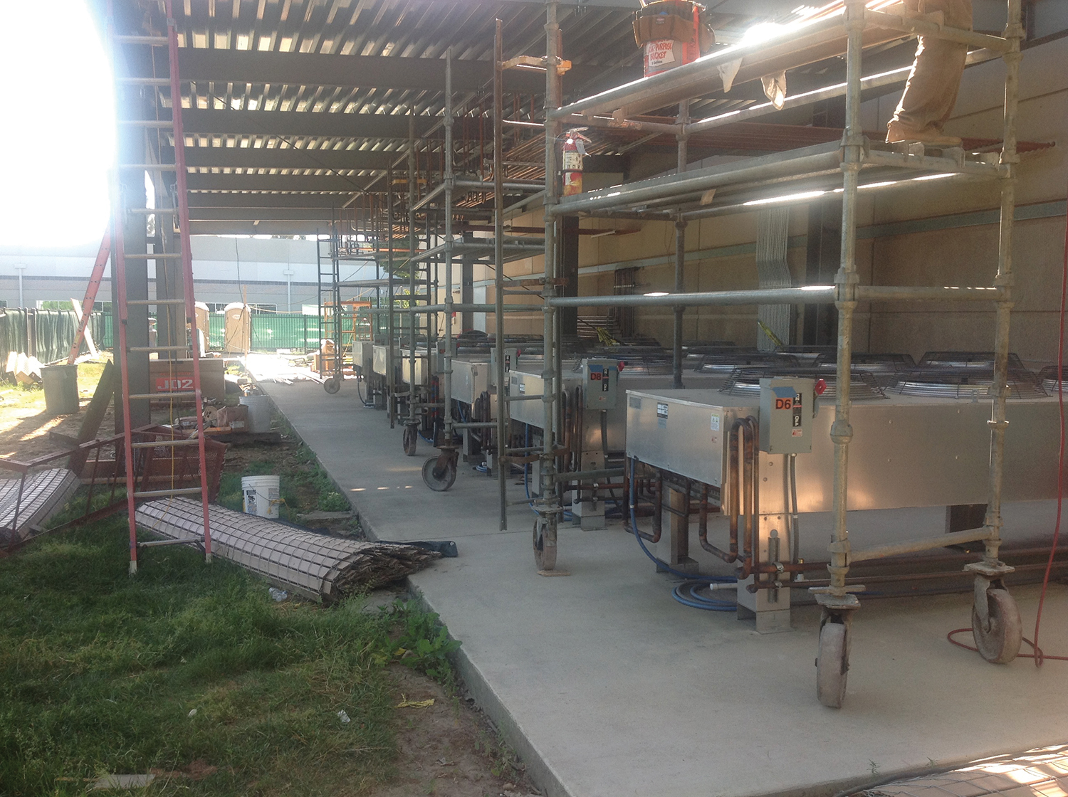
Figure 4. The first floor economizer is just outside the plastic structures in the exterior wall of a data hall.
On the first floor, work began on a 2,000-ft2 economizer. Rudolph and Sletten’s crew excavated and placed large concrete footings to accept new structural steel columns. The new footings tied directly into the existing footing of the building. As soon as the concrete met its compressive strength requirements, the new steel was installed inches away from the data room walls (see Figure 4).
CU Phased relocation
Next, roofs needed to be installed on the new penthouse and on the first floor economizer. This provided a unique obstacle; if the roof deck were to be completed, heat from the condensing units would be trapped under the roof area resulting in AHU shutdowns, and there would be no access to systematically shut down CUs to relocate them onto the new rooftop. The solution was to leave out the center portion of the new roof (see Figure 5). This allowed heat to escape as well as provide an access point for the cranes to move the CUs to the new roof area. Once the leave-out bay was constructed McKesson started relocating CUs to the new penthouse roof (see Figure 6).
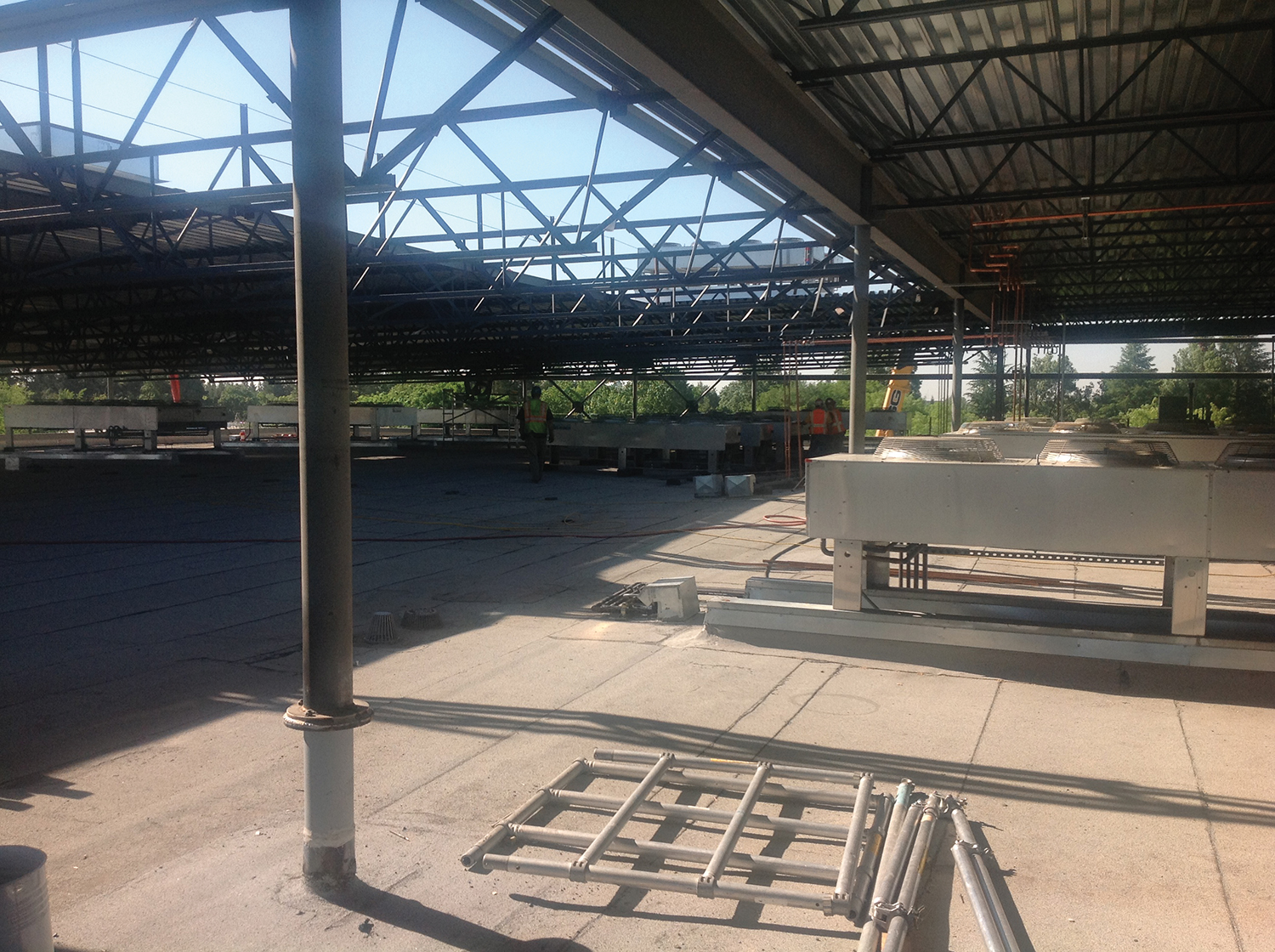
Figure 5. Creative construction sequencing made it possible to build new economizers and a penthouse without risking damage to the data center and while maintaining cooling to an operating facility.
Building the economizer on the first floor posed some of the same challenges as there were condensing units under that roof area. Roof decking had to be placed in three different phases. McKesson installed a third of the roof decking and then relocated come of the CUs from under the structure to the new roof of the first floor structure. Once this was successful, the second and third phases of roof deck and relocation of CUs commenced.
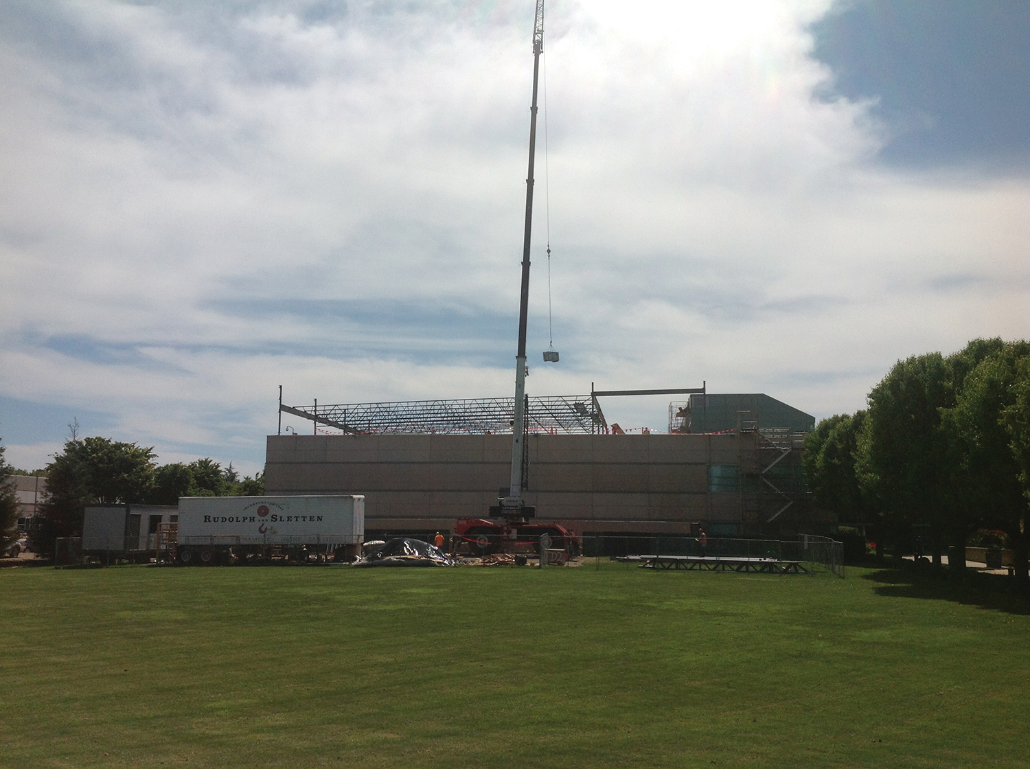
Figure 6. Cranes were needed at time points in the program, first to move steel into place and later for CUs
Retrofitting AHUs
With the penthouse and first floor economizers well under way, it was time to retrofit the CRACs. Every AHU on the second floor had to be retrofitted with new ductwork to provide either outside or return air. Ductwork was fitted with dampers to modulate between outside air and return air or mix the two when outside air is too cold. Approximately 30 new penetrations in the old roof were needed to supply the AHU with outside air. The new roof penetrations housed the new ductwork for the AHUs as well as structural steel to stiffen the roof and support the ductwork (see Figure 7).
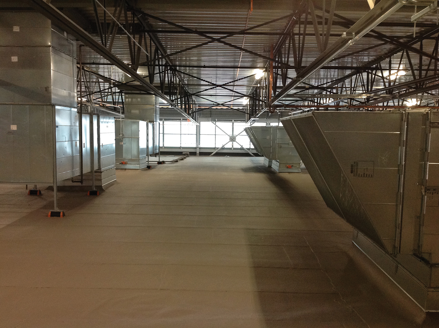
Figure 7. Ductwork was the last stage in bringing the second floor economizer on line.
The second floor computer room retrofit was performed in sections with a temporary anti-static fire resistant poly barrier installed to maintain the server area during construction. Once the temporary barriers were installed and the raised flooring protected, the ceiling could be removed to start fitting up the new ductwork.
The phased demolition of the roofing began at the same time. Several high-powered magnets holding welding blankets tight against the roof facilitated welding of the new structure at the roof penetration. These steps ensured all debris, welding slag, and unwanted materials would not fall into the second floor server room. Ductwork for supply air to the AHUs stopped at the old roof, while the new exhaust went up to the new penthouse roof.
The First Floor Economizer
The first floor air economizer presented its own unique set of challenges. In order to get outside air to the data center, the 2,000-ft2 first floor economizer was built before being connected to the existing data center. Once connected, outside air would be pulled in through a fan wall and pushed under the raised floor to provide cooling to the servers. Newly installed exhaust fans would draw exhaust from the Hot Aisles out through the roof of the mechanical room. The economizer was built on the same location as a CU farm that held the 30-ton condensers for the data center’s first floor. The interior buildout began once these CUs were moved to the roof of the ground floor economizer and started operation.
A temporary perimeter wall erected inside the data center where the two buildings adjoin protected equipment and provided a dustproof barrier. The temporary wall was constructed of a 2-hour-fire-rated board with anti-static fire retardant connected to the board on the data center side. There was approximately 6 ft between the servers and the existing wall and approximately 2 ft between the equipment and the temporary wall. McKesson and Rudolph and Sletten planned ways to remove the temporary wall to allow equipment replacement in the event of equipment failure, In addition, staff monitored differential pressure between the data center and the construction area to ensure the data center stayed in a positive pressure to keep dust from entering the facility. A professional service cleaned the data center daily and weekly to ensure the room stayed at a clean room status.
Once temporary containment was in place, deconstruction commenced. The plasterboard was removed to expose the perimeter precast concrete wall. Over 1,000 ft2 of precast concrete perimeter wall was removed, and new structural steel was welded in place to support the opening. After the steel was in place, sections of the precast concrete wall were carefully saw cut inside the first floor economizer and removed.
New construction began as soon as the all these preparations were ready. A new wall inside the data center, made of metal stud framing and insulated foam board, now separates the two areas. A new sandwich panel system separates the outside air intake from the exhaust. Dampers line the ceiling, between the outside air intake and exhaust, to allow for mixing and re-use of air. An expansion joint capable of moving up to 10 inches to protect against any potential seismic event lines the connecting walls and rooftop of the first floor economizer.
Controls
Outside air cooling on the second floor is provided by modulating the outside air supply damper and the warm-air plenum mixing damper of each AHU to supply a specific temperature under the floor when outside air temperatures are cool enough for this mode of cooling. Temperature sensors located throughout the penthouse air intake area enable and disable the second floor outside air cooling system. Each AHU controls its own discharge temperature as each AHU has its own outside air supply damper and mixing damper.
Fixed-speed AHU fans move the supply air. The AHU controls are used to control its compressors. On initiation of outside air cooling, each outside air AHU damper opens wide and the mixing damper closes.
As outside air is cooler than warm plenum return air, the AHU controls shut off its compressors. When outside air cooling mode is initiated, four exhaust fans in each of the two outside air cooled rooms on the second floor are enabled. These variable speed exhaust fans modulate their speed according to the differential pressure between the computer room and the office area lobby space. If outside air temperature decreases and becomes too cool, the AHU mixing damper partially opens while the outside air supply damper partially closes. When the outside air temperature in the air intake area rises to a value too high for supply air, the outside air supply damper closes fully and the mixing damper opens wide. The AHU return temperature senses the higher temperature of the plenum air and starts its compressors. The exhaust fans are shut down and their exhaust dampers closed as the AHUs transition to recirculation cooling mode.
The first floor outside air cooling regime does not use the AHU fans to supply air under the floor but instead employs a fan wall. The control of the fan wall, exhaust fan gallery, outside air supply dampers, and mixing dampers is split into thirds. Each third of the system is independently controlled. When the outside air temperature is low enough to initiate cooling, the supply damper opens wide and the mixing damper remains closed. The supply fan speed is controlled by variable frequency drives (VFD) with a third of the fans acting in concert to a raised floor differential pressure signal. Exhaust fan speed is controlled by the differential pressure between the computer room and the lobby, again by thirds. When outside air cooling is initiated, and after a time delay to allow outside air cooling to take effect, a signal is sent to each AHU to stop its blower fan and compressors. A signal is also sent to close the AHU return damper to preclude back flow though the shutdown AHU. As outside air temperature decreases, the supply damper and mixing damper are modulated to maintain a minimum supply temperature to the raised floor. When the temperature of the outside air rises to an unacceptable level, the AHU return dampers are opened and AHU units restart in sequence. Warm air is dawn through the AHU and this initiates compressor cooling. The fan wall and exhaust fans are then sequenced off and the outside air supply and mixing dampers close.
The controls consist of two programmable logic controllers, one for the first floor and one for the second floor controls.
Fire Protection of New Areas
Both the new penthouse addition and the ground floor economizer addition are protected by pre-action dry pipe sprinkler systems. Two sets of VESDA (very early smoke detector aspirating) systems monitor each room for smoke. The first system monitors for smoke within the room. The second system senses air at the louvers of the first floor and penthouse air intakes. If these VESDA units at the louvers sense increased smoke, they signal interior VESDA units to increase their smoke alarm thresholds by the same value. This precludes a false actuation of the sprinkler system due to fires outside the economizer or penthouse area.
Prior to the outside air upgrade the building sprinkler system was supplied directly from the street. The addition of the penthouse required the installation of a building fire pump to boost water pressure. The new 30 horsepower electric fire pump is fed directly from a utility transformer.
Conclusion
The McKesson Data Center Outside Air Project achieved its goal of reducing the required power load and is currently running 550 kW below historic levels for this time of year. The collaborative construction plan between McKesson and Rudolph and Sletten ensured zero downtime and minimal disruption to the 24/7 operational mission critical center. The retrofitted system will continue to reduce power loads and achieve significant cost savings.

Wayne Everett
With 25 years of experience in electrical and data center construction, Wayne Everett is team lead of the Data Center Facilities Engineering Department at McKesson. He oversees design and strategic planning, facilities maintenance, infrastructure upgrades, construction, and special projects for McKesson’s critical hosting and networking facilities. His team consists of engineers, data center facilities technicians, electricians, and HVAC mechanics. Prior to coming to McKesson, he worked as a project manager for electrical contractors in the Atlanta area, where he managed a wide range of electrical construction projects including critical systems. He also holds an electrical contractor license in the state of Georgia. Mr. Everett recently celebrated 10 years with McKesson.

Dean Scharffenberg
Dean Scharffenberg, a 19-year veteran of McKesson, serves as the senior director of Data Center Engineering and Automation. He provides data center analysis for McKesson’s acquisitions and enterprise data center strategy/design. Mr. Scharffenberg’s primary responsibilities include oversight of data center facilities, enterprise storage, data center networks, server engineering, and computer systems installation. As a mechanical engineer, he has a passion for engineering with special interest in fluid dynamic, electrical distribution, virtualization, and capacity planning.

Coleman Jones
As a project manager for general contractor Rudolph and Sletten, Coleman Jones is responsible for managing all aspects of the construction project. His primary duties include negotiating and administrating contracts, supervising project team members, monitoring job costs and schedules, and working closely with the architect and the owner to ensure the project is completed on time and within budget. A graduate of the California State University Chico Construction Management program, Mr. Jones is a LEED Accredited Professional with seven years’ experience working on critical systems for technology and health-care clients.


 Getty Images


