Unipol Takes Space Planning to a New Level
Municipal requirements imposed difficult space considerations for Italian insurance company’s Tier IV data center
By Andrea Ambrosi and Roberto Del Nero
Space planning is often the key to a successful data center project. Organizing a facility into functional blocks is a fundamental way to limit interference between systems, reduce any problem related to power distribution, and simplify project development. However, identifying functional blocks and optimizing space within an existing building can be extremely complex. Converting an office building into a data center can cause further complexity.
This was the challenge facing Maestrale, a consortium of four engineering companies active in the building field including Ariatta Ingegneria dei Sistemi Srl as the mechanical and electrical engineer, when a major Italian insurance company, UnipolSai Assicurazioni S.p.a (UnipolSai), asked it to design a data center in an office building that had been built at the end of the 1980s in Bologna, Italy. UnipolSai set ambitious performance goals by requiring the electrical and mechanical infrastructure to be Uptime Institute Tier IV Certification of Constructed Facility and very energy efficient.
In addition, the completed facility, designed and built to meet UnipolSai’s requirements, has the following attributes:
• 1,200 kilowatts (kW) maximum overall IT equipment load
• UPS capacity: not less than 10 minutes
• Four equipment rooms having a total area of 1,400 square meters (m2)
• Cold Aisle/Hot Aisle floor layouts : In an energy-conscious project, all innovative free-cooling technologies must be considered.
After a thorough investigation of these free-cooling technologies, Ariatta chose direct free cooling for the UnipolSai project.
MUNICIPAL RESTRICTIONS
The goal of the architectural and structural design of a data center is to accommodate, contain, and protect the mechanical, electrical, and IT equipment. The size, location, and configuration of the mechanical and electrical infrastructure will determine the architecture of the rest of the building. In a pre-existing building, however, this approach does not always apply. More often, builders must work around limitations such as fixed perimeter length and floor height, floors not capable of bearing the weight of expected IT equipment, lack of adjoining external spaces, and other restrictions imposed by municipal regulations. In this project, a series of restrictions and duties imposed by the Municipality of Bologna had a direct impact on technical choices, in particular:
• Any part or any piece of equipment more than 1.8-meters high on the outside yard or on any external surface of the building (e.g., the roof) would be considered added volume, and therefore not allowed.
• Any modification or remodelling activity that changed the shape of the building was to be considered as incompatible with municipal regulations.
• The location was part of a residential area with strict noise limits (noise levels at property lines of 50 decibels [dbA] during the day and 40 dbA at night).
New structural work would also be subject to seismic laws, now in force throughout the country. In addition, UnipolSai’s commitment to Uptime Institute Tier IV Certification required it to also find solutions to achieve Continuous Cooling to IT equipment and to Compartmentalize ancillary systems. The final design incorporates a diesel rotary UPS (DRUPS) in a 2N distribution scheme, a radial double-feed electrical system, and an N+1 mechanical system with dual-water distribution backbone (Line 1 and Line 2) that enable the UnipolSai facility to meet Uptime Institute Tier IV requirements. Refrigerated water chillers with magnetic levitation bearings and air exchangers inserted in an N+1 hydraulic scheme serve the mechanical systems. The chillers are provided with double electric service entrance controlled by an automatic transfer switch (ATS). The DRUPS combine UPS and diesel engine-generator functions and do not require battery systems, which are normally part of static UPS systems. Uptime Institute Tier IV requires Compartmentalization, which necessitates more space. Eliminating the batteries saved a great deal of space. In addition, using the DRUPS to feed the chillers ensured that the facility would meet Tier IV requirements for Continuous Cooling with no need for storage tanks, which would be difficult to place in this site. The DRUPS also completely eliminated cooling requirements in the UPS room because the design ambient temperature would be around 30°C (maximum 40°C). Finally, using the DRUPS greatly simplified the distribution structure, limiting the ATSs on primary electric systems to a very minimum.
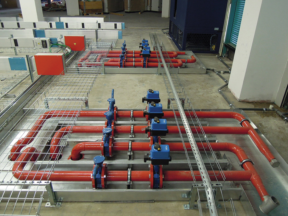
Municipal restrictions meant that the best option for locating the DRUPS and chillers would require radically transforming some areas inside building. For example, Ariatta uncovered an office floor and adapted structures and waterproofing to install the chiller plant (see Figures 1 and 2).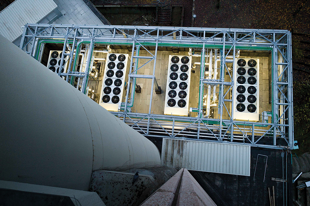
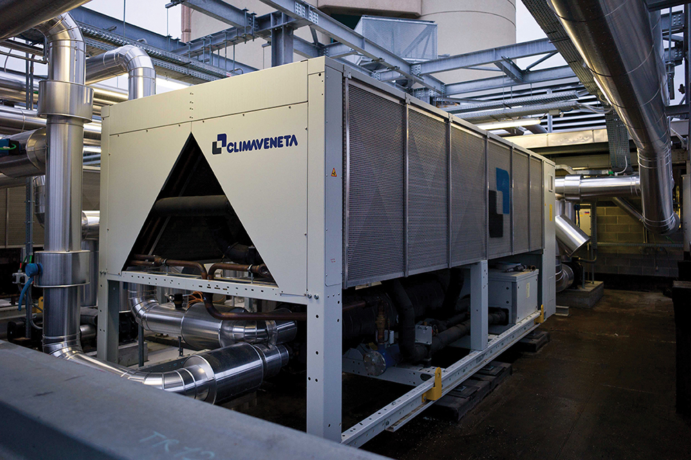
Figures 1 and 2. Bird’s eye and ground level views of the chiller plant.
Positioning the DRUPS posed another challenge. In another municipality, its dimensions (12-m length by 4.5-m height), weight, and maintenance requirements would have guided the design team towards a simple solution, such as installing them in containers directly on the floor. However, municipal restrictions for this location (1.8-m limit above street level) required an alternative solution. As a result, geological, geotechnical, and hydrogeological studies of the site of the underground garage showed that:
• Soil conditions met the technical and structural requirements of the DRUPS installation.
• The stratum was lower than the foundations.
• Flood indexes are fixed 30 centimeters above street level (taking zero level as reference).
The garage area was therefore opened and completely modified to contain a watertight tank containing the DRUPs. The tank included a 1.2-m high parapet to prevent flooding. The tank was equipped with redundant water lifting systems fed by the DRUPS (see Figures 3 and 4).
Figures 3 and 4. Particular care was given to protect the DRUPS against water intrusions. Soundproofing was also necessary.
Meeting the city’s acoustic requirements required soundproofing the DRUPS machines, so the DRUPS systems were double shielded reducing noise levels to 40 decibels (dbA) at 10 m during normal operation when connected to mains power. Low-noise chillers and high-performance acoustic barriers helped the entire facility meets its acoustical goals.
After identifying technical rooms and allocating space for equipment rooms, Ariatta had to design systems that met UnipolSai’s IT and mechanical and electrical requirements, IT distribution needs, and Uptime Institute Tier IV Compartmentalization requirements.
The floors of the existing building did not always align, especially on lower stories. These changes in elevation were hard to read in plans and sections. To meet this challenge, Starching S.R.L. Studio Architettura & Ingegneria and Redesco Progetti Srl, both part of the Maestrale Consortium, developed a three-dimensional Revit model, which included information about the mechanical and electrical systems. The Revit model helped identify problems caused by the misalignment of the floors and conflict between systems in the design phase. It also helped communicate new information about the project to contractors during the construction phase (see Figure 5 and 6).
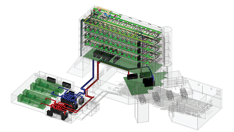
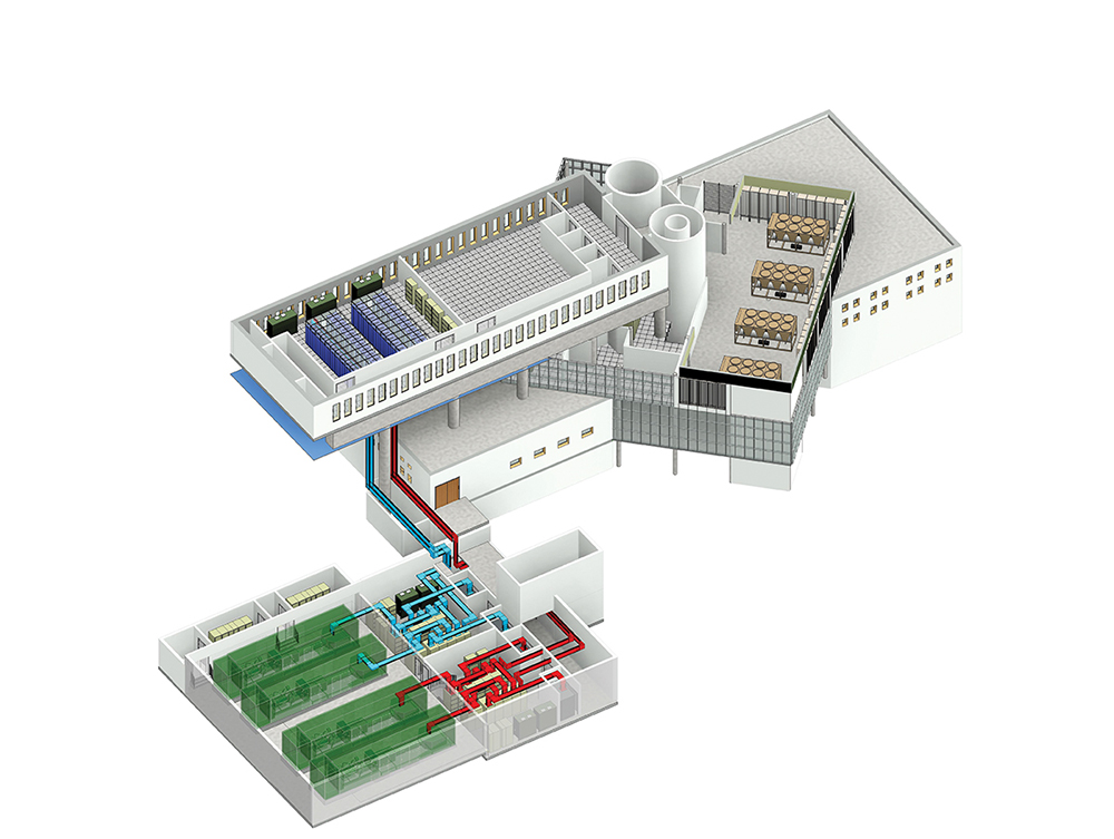
Figures 5 and 6. Revit models helped highlight changes in building elevations that were hard to discern in other media and also aided in communication with contractors.
The use of 3D models is becoming a common way to eliminate interference between systems in final design solutions, with positive effects on the execution of work in general and only a moderate increase in engineering costs.
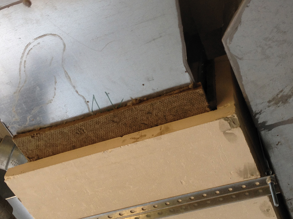
Figure 7. Fire-rated pipe enclosure
At UnipolSai, Compartmentalizing ancillary systems represented one of the main problems to be resolved to obtain Uptime Institute Tier IV Certification because of restrictions caused by the existing building. Ariatta engaged in continuous dialogue with the Uptime Institute to identify technical solutions. This dialogue, along with studies and functional demonstrations carried out jointly with sector specialists, led to a shared solution where two complementary systems that form the technological backbone are compartmentalized, with respect to one another (see Figure 7). The enclosures, which basically run parallel to each other, have:
• An external fire-resistant layer (60 minutes, same as the building structure)
• An insulation layer to keep the temperature of the technological systems within design limits for 60 minutes
• A channel that contains and protects against leaks absorbs shocks
• Dedicated independent mounting brackets. This solution was needed where the architectural characteristics of the building affected the technological backbone (see Figure 8).
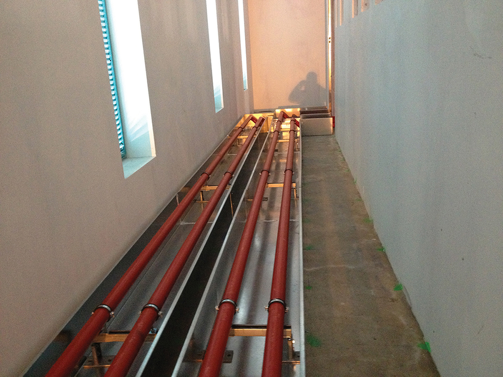
Figure 8. The layout of the building limited the potential paths for pipe runs.
ENERGY EFFICIENCY
The choice of direct free cooling was made following an environmental study intended to determine and analyse the time periods when outdoor thermo-hygrometric conditions are favorable to the indoor IT microclimate of the UnipolSai data center as well as the relevant technical, economic, and energy impact of free cooling on the facility. The next-generation IT equipment used at UnipolSai allows it to modify the environmental parameters used as reference.
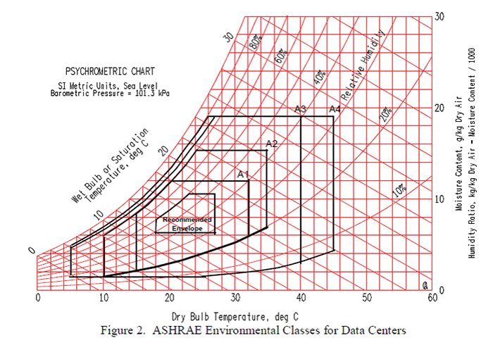
Figure 9. UnipolSai sized equipment to meet the requirements of ASHRAE’s “Thermal Guidelines for Data Processing Environments, 3rd edition,” as illustrated by that publication’s Figure 2.
The air conditioning systems in the data center were sized to guarantee temperatures between 24–26°C (75-79°F) per Class A1 equipment rooms as per ASHRAE “Thermal Guidelines for Data Processing Environments, 3rd edition”, in accordance with ASHRAE psychrometric chart (see Figure 9). The studies carried out showed that, in the Bologna region specifically, the outdoor thermo-hygrometric conditions are favorable to the IT microclimate of the data center about 70% of the time with energy savings of approximately 2,000 megawatt-hours. Direct free cooling brought undeniable advantages in terms of energy efficiency but introduced a significant functional complication issue related to Tiers compliance. The Tier Standards do not reference direct free cooling or other economization systems as the Tier requirements apply regardless of the technology. Eventually, it was decided that the free cooling system had to be subordinated to IT equipment continuous operation and excluded every time there was a problem with the mechanical and electrical systems, in which case continued operations would be ensured by the chiller plant.
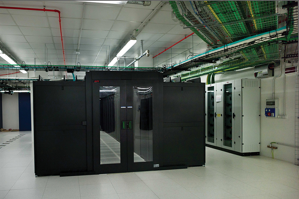
Eventually, it was decided that the free cooling system had to be subordinated to IT equipment continuous operation and excluded every time there was a problem with the mechanical and electrical systems, in which case Continous Cooling would be ensured by the chiller plant. The direct free cooling functional setting, with unchanneled hot air rejection that was dictated by the pre-existing architectural restrictions, dictated the room layout and drove the choice of Cold Aisle containment. The direct free-cooling system consists of N+1 CRACs placed along the perimeter of the room, blowing cool air into a 60-inch plenum created by the access floor. The same units manage the free-cooling system. Every machine is equipped with a dual feed electric entrance controlled by an ATS and connected to a dual water circuit through a series of automatic valves (see Figure 10).
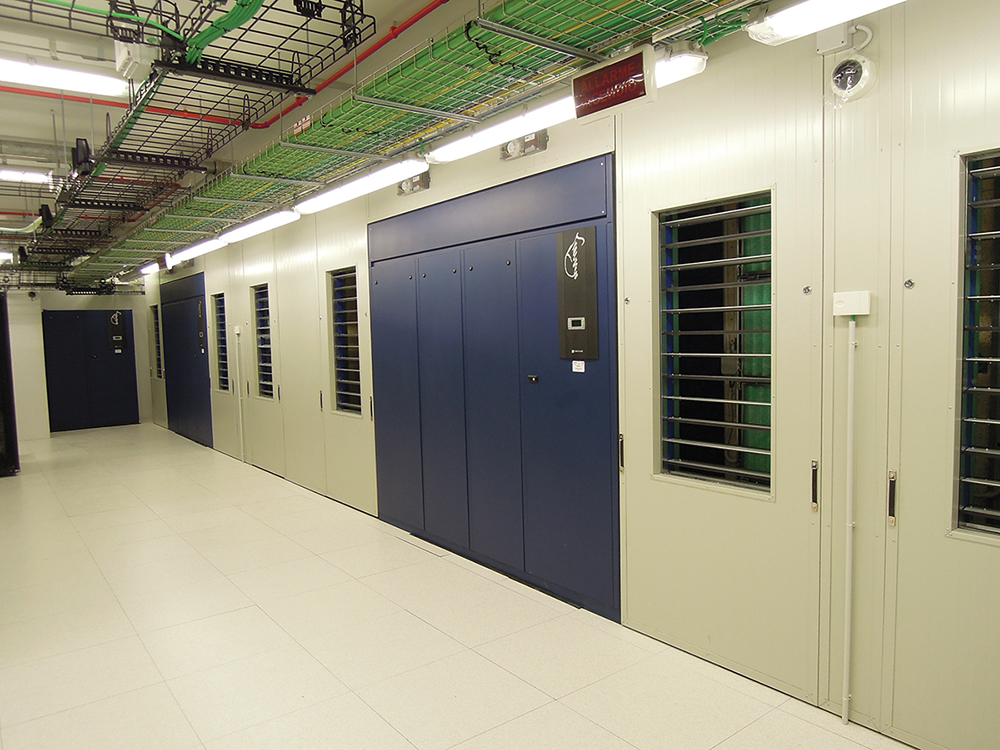
Figure 10. CRACs are connected with a dual-feed electric entrance controlled by an ATS and connected to a dual water circuit.
Containing the Cold Aisles caused a behavioral response among the IT operators, who normally work in a cold environment. At UnipolSai’s data center, they feel hot air heat when entering the data center. Design return air temperatures in the circulation areas are 32–34°C (90-93°F), and design supply air temperatures are 24–26°C (75-79°F). It became necessary to start an informational campaign to prevent alarmism in connection with room temperatures in the areas outside the functional aisles (See Figures 11-13).
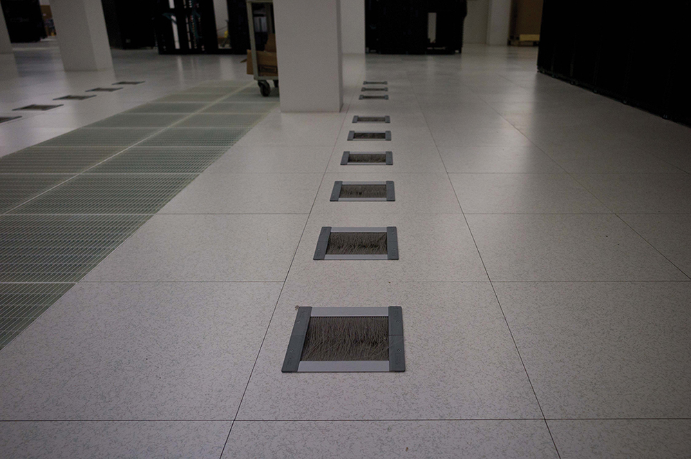
Figures 11-13. Pictures show underfloor piping, containers, and raised floor environment.
Prefabricated electric busbars placed on the floor at regular intervals provide power supply to the IT racks. This decision was made in collaboration with UnipolSai technicians who considered it the most flexible solution in terms of installation and power draw, both initially and to accommodate future changes (see Figure 14 and 15).

Figure 14. Electric busbar
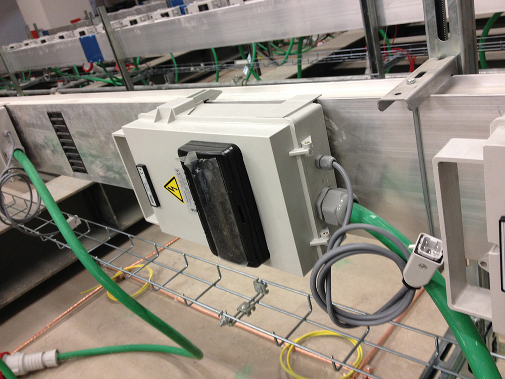
Figure 15. Taps on the busbar allow great flexibility on the data center floor and feed servers on the white space floor below.
In addition, a labeling system involving univocal synthetic description (alphanumeric code) and color coding, which allows a quick visual identification any part of any system makes simplifies the process of testing, operating, and managing all building systems (see Figure 16 and 17).
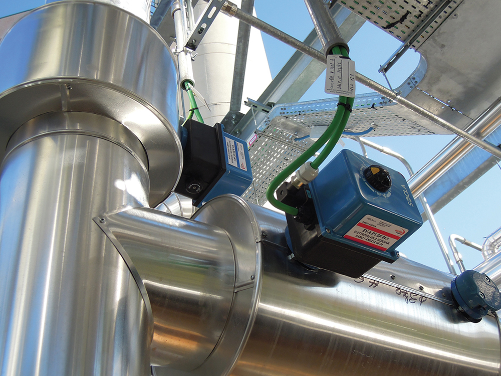
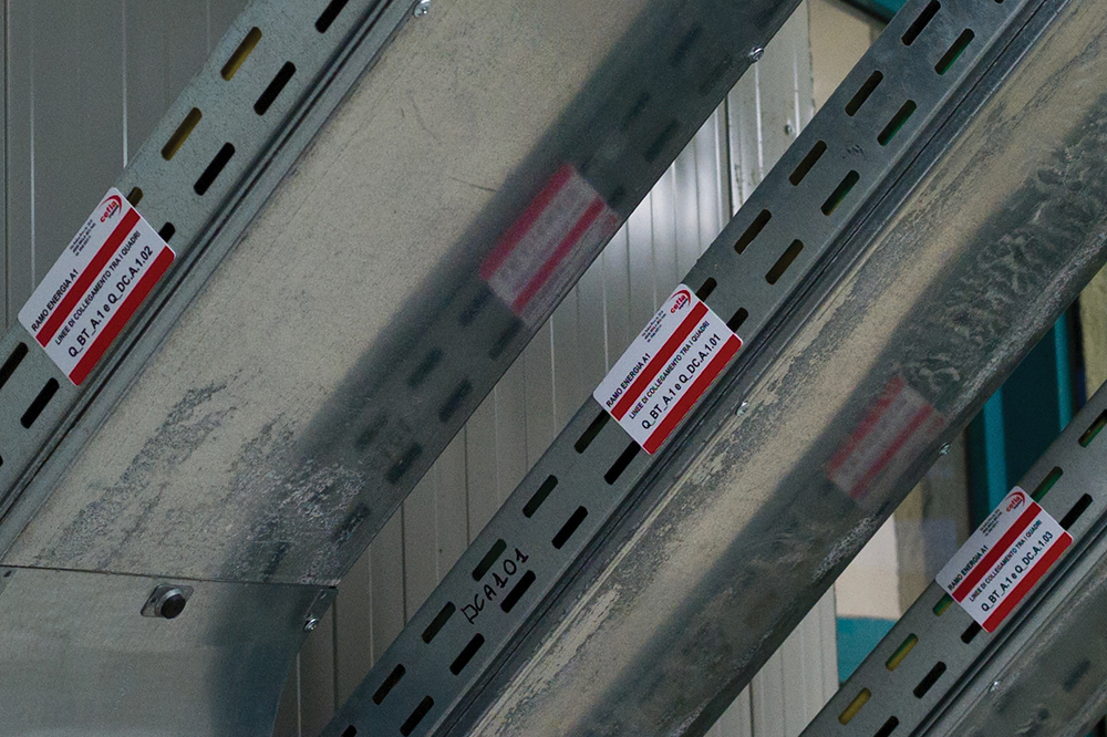
Figure 16-17. UnipolSai benefits from a well-thought out labeling system, which simplifies many aspects of operations.
FINAL TESTING
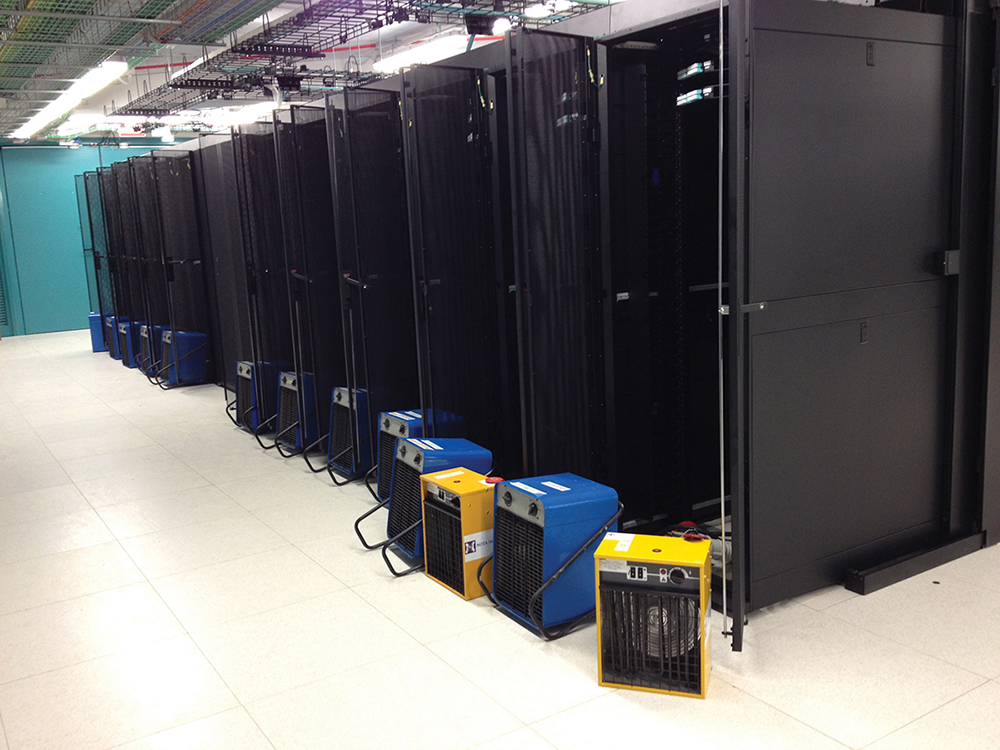
Functional tests were carried out at nominal load with the support of electric heaters, distributed in a regular manner within the equipment rooms and connected to the infrastructure feeding the IT equipment (see Figure 18-19). Also, Uptime Institute observed technical and functional tests were as part of Tier IV Certification of Constructed Facility (TCCF). The results of all the tests were positive; final demonstrations are pending. The data center has received Uptime Institute Tier IV Certification of Design Documents and is in progress for Tier IV Certification of Constructed Facility.
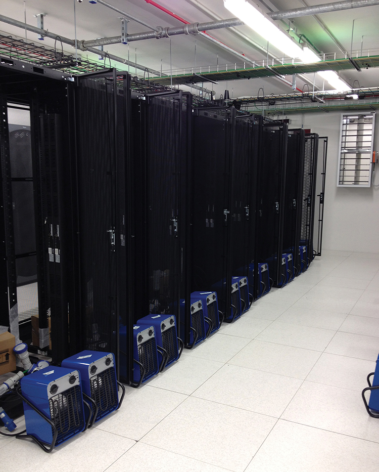
Figure 18-19. Two views of the data center floor, including heaters, during final testing.
 To fully respond to the energy saving and absorption control policy of UnipolSai, the site was equipped with a network of heat/cooling energy meters and electrical meters connected to the central supervision system. Each chiller, and pumping and air handling system was specifically metered on electrical side, with chillers metered on the thermal side. Each electric system feeding IT loads is also metered.
UnipolSai also adopted DCIM software that, if properly used, can represent the first step towards an effective organization of the maintenance process, essential for keeping a system efficient and operational, independently from its level of redundancy and sophistication.

Andrea Ambrosi
Andrea Ambrosi, is project manager, design team manager and site manager at Ariatta Ingegneria dei Sistemi Srl (Ariatta). He is responsible for the executive planning and management of operations of electrical power, control and supervision systems, safety, and security and fire detection systems to be installed in data centers. He has specific experience in Domotics and special systems for the high-tech residential sector. He has been an Accredited Tier Designer since 2013 and Accredited Tier Specialist since 2014.
Roberto Del Nero, is a project manager and design team manager at

Roberto Del Nero
Ariatta, where he is responsible for the executive planning and management of mechanical plants, control and supervision systems, fire systems, plumbing and drainage to be installed in data center. He has been LEED AP (Accredited Professional) since 2009, Accredited Tier Designer since 2013 and Accredited Tier Specialist since 2014.

 Getty
Getty
 Uptime Institute


