Switzerland’s First Tier IV Certified Facility Achieves Energy Efficiency
Telecommunications company Swisscom AG builds a new data center in Berne, one of seven Tier IV data centers in Europe
By Beat Lauber, Urs Moell, and Rudolf Anker
Swisscom AG, a Switzerland-based telecommunications company, recently built a new data center in Berne, Switzerland. Swisscom spent three years and invested around US$62.5 million to build a highly efficient and reliable data center. Following two years of construction, the new Berne-Wankdorf Data Center was fully operational in January 2015.
The Swisscom Berne-Wankdorf Data Center xDC, Phase 1, is one of only seven data centers in Europe awarded Uptime Institute Tier IV Certification of Constructed Facility and the first in Switzerland. It also has top ratings for energy efficiency, thanks to an innovative cooling concept, and won a 2015 Brill Award for Efficient IT. The new building is the largest of the 24 data centers operated by Swisscom in Switzerland (see Figure 1).
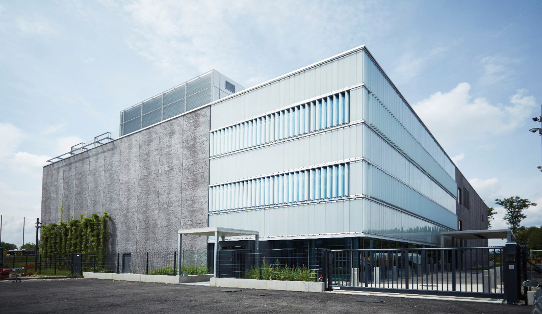
Figure 1. Exterior of Swisscom’s Berne Wankdorf data center, photo Nils Sandmeier
The data center is designed on a modular principle, permitting future expansion whenever necessary. This ensures the required degree of investment security for Swisscom and its customers. The initial stage includes four modules with access areas for personnel and equipment. Swisscom can add capacity as needed, up to a total of seven modules. The data center will house around 5,000 servers and approximately 10,000 customer systems.
MODULAR 2N CONCEPT
Each module in Berne-Wankdorf Data Center has an IT capacity of 600 kW (see Figure 2). Modules A to D, which have a total capacity of 2.4 megawatts (MW), were built in the first phase of construction. Modules E, F, and G are to be built at some point in the future, either individually or in parallel. In addition to the modules for production, an entrance module housing a reception area, a lodge, workstations, and break-out spaces have also been built.
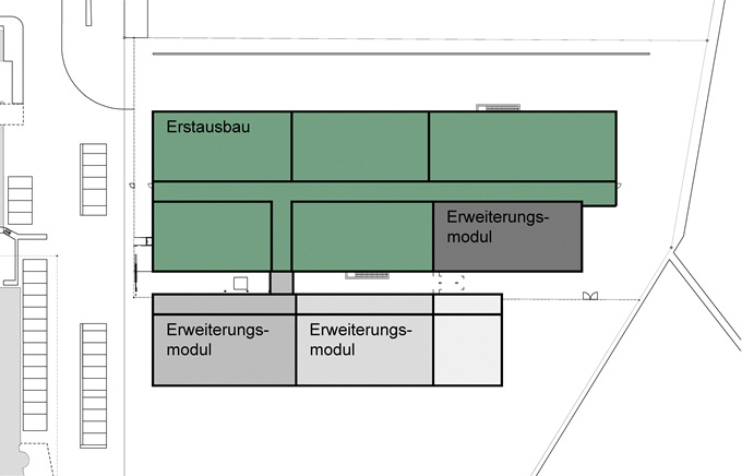
Figure 2. Site layout with extension modules
Two independent cells (electrical power supply and cooling) rated at 150% of the nominal power demand supply each module. This means that either cell can cover the entire power requirement of a module. The initial configuration includes four cells to supply four modules. Additional modules, each with an individual supply cell, can be attached without interruption. The supply is made via two independent paths, providing uninterrupted electricity and cooling.
SITE ARCHITECTURE
The building totals four stories, three above ground and one below ground. Server rooms are located on the ground and first floors (see Figure 3). Fuel and water tanks, as well as storage areas, are located in the basement. Outside air cools the energy supply equipment. For this reason most of the top floor is dedicated to housing building services (see Figure 4). The frame of the building as well as its floors, ceilings, and walls are made primarily from prefabricated sections of concrete (see Figure 5). Only the basement and the sections providing reinforcement for seismic protection are constructed from cast-in-situ concrete. The façade also consists of prefabricated sections of concrete 15 meters (m) high with inlaid thermal insulation. The server rooms do not have visible pillars. Joists 1.05 m high support the ceilings and span 13.8 m above the IT equipment. The space between the joists is used for air movement. Warm air from the server racks is fed through a suspended ceiling to recirculating air coolers. This removes the need for a raised floor in the server rooms (see Figure 6).
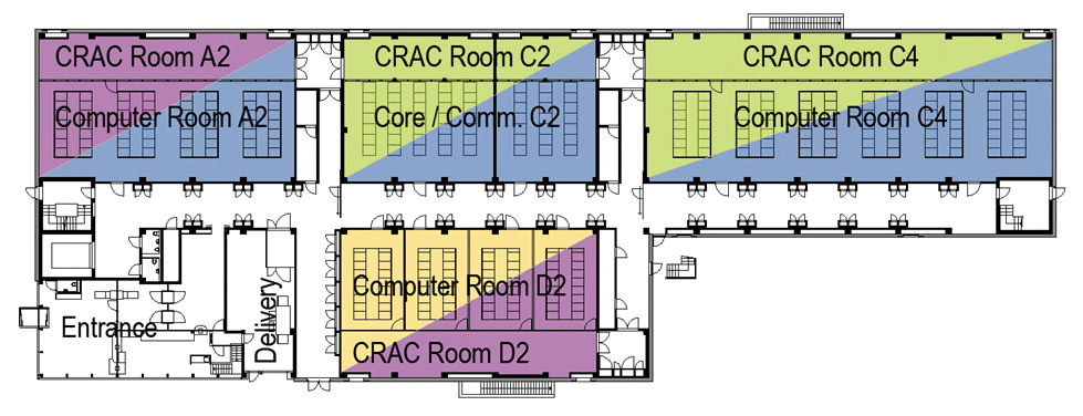
Figure 3. Ground floor layout
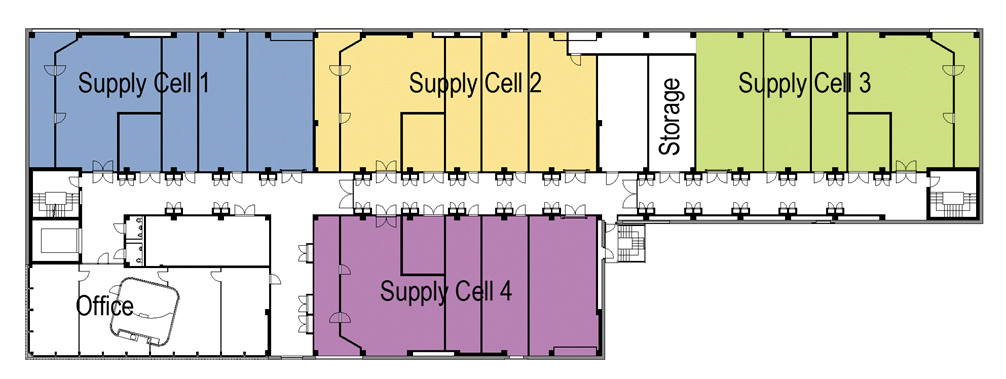
Figure 4. Second floor layout
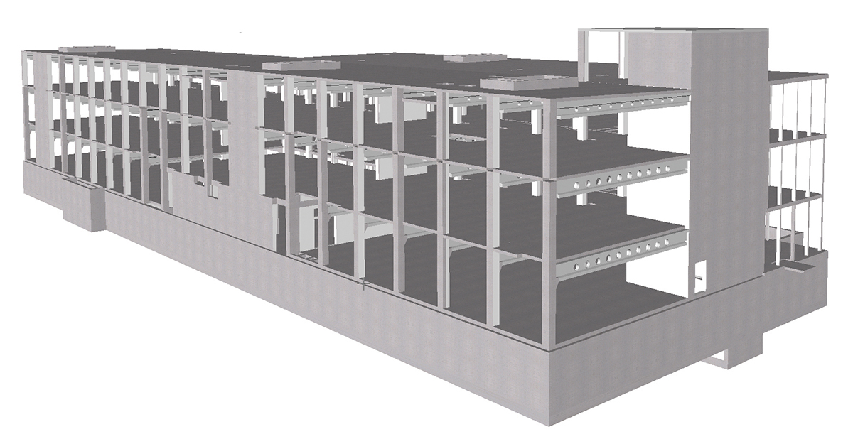
Figure 5. Bearing structure

Figure 6. System profile through a server room
EFFICIENT COOLING SYSTEMS
An adiabatic re-cooling system with rainwater enables Swisscom to eliminate mechanical chillers completely. As long as the outside temperature is below 21°C (70°F), the re-cooling units work on dry free cooling. When the temperature rises above 21°C (70°F), water added to the warm air draws out heat through evaporation.
The cooled water from the re-cooling units is then used to supply the CRACs to cool the IT systems. The racks are configured in a Hot Aisle containment cube that keeps the cold supply air and warm exhaust air entirely separate. Warm air from the Hot Aisle is supplied to the recirculating air coolers via a suspended ceiling. This layout means that the majority of the room is on the cool side of the cooling system. As a result, relatively pleasant working conditions are assured, despite relatively warm cooling air (see Figure 7).

Figure 7. Pictorial schematic of the cooling supply
The CRACs are specifically designed to a high cooling water temperature 26° C (79°F) and lowest possible inlet air temperature 28°C (82°F). The exhaust air temperature is 38° C (100°F). With the exception of a small number of damp hot days in the summer, this ecological cooling concept can supply air cooler than 28°C (82°F) all year round.
Retrospective calculations (see Figure 8) based on data from the equipment show that the maximum foreseeable temperature of the supply air would be 30°C (86°F) in the worst-case scenario (full load, failure of an entire supply cell, extreme climate values from the last 20 years).
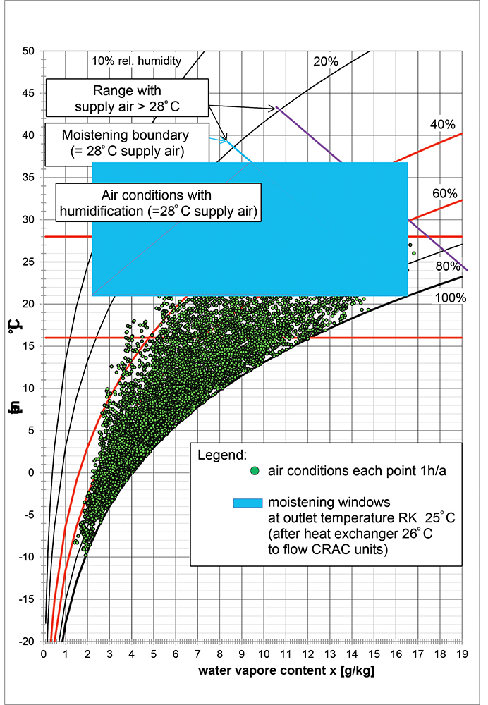
Figure 8. h-x diagram for air conditions 2005
Rainwater for the adiabatic cooling system is collected from the roof, where there are two separate tanks, each of which can hold enough water to support at least 72 hours of operation. Two separate networks supply water pumper from the two tanks to hybrid recoolers through redundant water treatment systems. The recoolers can be supplied either from the osmosis tank or directly from the rainwater tank. If there is not enough rainwater, water is drawn from the city water network to fill the tanks. During the heating season, the heat produced from the cooling systems heats the building directly. Efficient heat distribution regulates the temperature in the rooms. The data center dissipates the remainder of the waste heat to the local energy supplier’s existing waste heat grid. The thermal energy from grid heats a residential quarter and swimming pools. The more consumers use this energy, the less the hybrid recoolers are operated, whereby a further energy-saving potential is utilized.
NOBREAK UPS
The Wankdorf Data Center does not use batteries but instead deploys SMS NoBreak equipment safeguards the uninterruptible power supply (UPS) using kinetic energy. Should the power supply fail, the NoBreak equipment uses flywheel inertia to ensure that operation continues uninterrupted until the diesel engine-generator sets start up (within seconds) to take over the energy supply (see Figure 9).
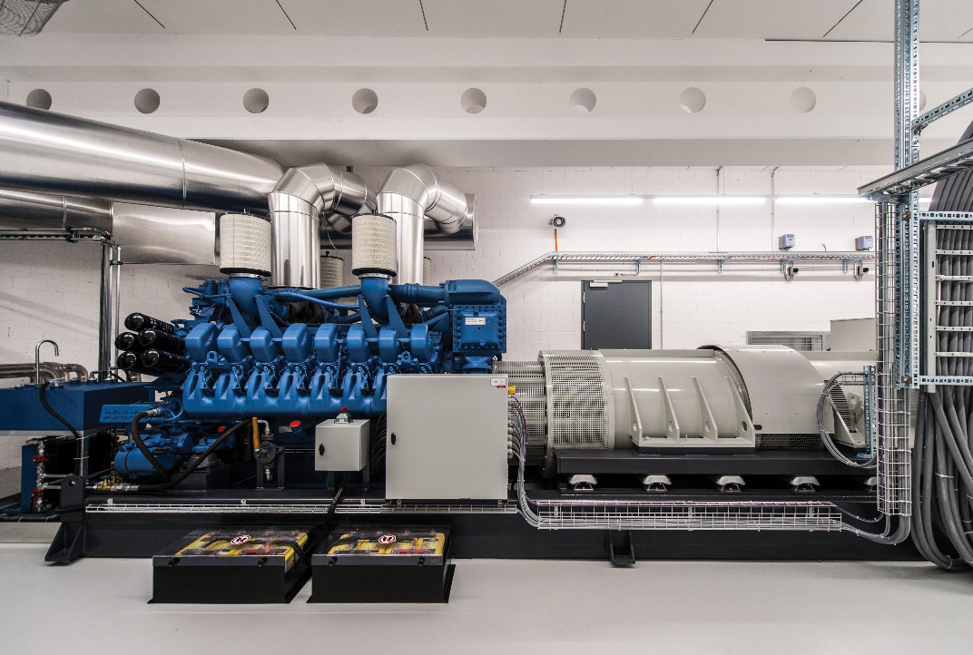
Figure 9. NoBreak equipment
EXTENSIVE BUILDING AUTOMATION
Essentially, the building automation system (BAS) comprises two redundant VMWare ESX servers on which the BAS system and an energy management tool are installed. While the building automation system supports all vital functions, the energy management tool is tasked with evaluating and recording energy measurements.
A redundant signalling system provides a back-up solution for alarm signals. The system has its own independent network. All measured values are displayed and recorded. An energy management function analyses the measured values so that energy efficiency can be continuously optimized.
MAXIMUM PROTECTION
From the selection of its location to its specific construction, from its physical protective measures to its advanced security and safety concept, the Berne-Wankdorf Data Center offers the maximum in protection. Access is strictly controlled with a biometric access control system and the site is monitored from a lodge that is staffed around the clock.

Beat Lauber
Beat Lauber is an approved visionary in the field of data center design. He is founding member and CEO of RZintegral AG, a leading Swiss company specializing in data center planning and engineering. His career includes more than 20 years of experience with critical infrastructures and involves notable challenges in design, planning, realization, and project management of large data center projectss. Audits and mandates for strategies complete his list of activities. Mr. Lauber graduated as Architect FH/SIA and made post-graduate studies in Business Administration and Risk Management and is Fire Protection Manager CFPA-E.

Urs Moell
Urs Moell is senior data center designer at RZintegral AG and has acquired a broad knowledge in strategies and layout of critical infrastructures as well as availability, energy efficiency, safety and security. He is in charge of the development and layout, architectural design and the optimal coordination of all trades for best-performance data centers. He graduated as Architect ETH and has 20 years of experience planning buildings as well.

Rudolf Anker
Rudolf Anker is head of Datacenter Management at Swisscom IT, where he has been since 2004. His responsibilities include project manager of new data centers, including planning, lifecycle, and operations. He initiated and provided overall project management for the new DC RZ Future and xDC data center buildings in Zollikofen and Wankdorf).
 2020
2020
 UI 2021


